Ubiquiti EdgePoint EP-R8 Quick Start Quide
- Categorie
- Convertoare media de rețea
- Tip
- Quick Start Quide
Acest manual este potrivit și pentru

Intelligent WISP Control
with FiberProtect
™
Model: EP-R8


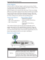
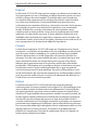
Introduction
Thank you for purchasing the Ubiquiti Networks® EdgePoint
™
Router. This Quick Start Guide is designed to guide you through
installation and includes the warranty terms.
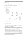
Package Contents
EdgePoint Router Wall-Mount
Bracket
Metal Straps
(Qty. 2)
Cable Sleeve
Intelligent WISP Control
with FiberProtect
™
Model: EP-R8
Gigabit PoE (54V, 1.5A) with
Mounting Bracket
Power Cord Quick Start
Guide
Installation Requirements
• 7 mm socket wrench
• S2 hex wrench
• Ground wire – min. 10 AWG (5 mm
2
) and max. length: 1m. Asa
safety precaution, ground the EdgePoint to a grounded mast,
pole, tower, or grounding bar.
• Shielded Category 5 (or above) cabling should be used for all
wired Ethernet connections and should be grounded through
the AC ground of the PoE.
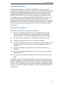
• We recommend that you protect your networks from
harmful outdoor environments and destructive ESD events
with industrial-grade, shielded Ethernet cable from Ubiquiti
Networks. For more details, visit: www.ubnt.com/toughcable
TERMS OF USE: Shielded Ethernet cable and earth grounding must be used as conditions of product
warranty. TOUGHCable
™
is designed for outdoor installations. It is the customer’s responsibility to
follow local country regulations, including operation within legal frequency channels, output power,
and Dynamic Frequency Selection (DFS) requirements.
1
Introduction

Hardware Overview
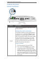
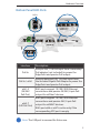
Bottom Panel Button
Reset
Button
Description
Reset
There are two methods to reset the EP-R8 to
factory defaults:
Runtime Reset (Recommended)
The EP-R8 should be running after bootup is
complete. Press and hold the Reset button
for about 10seconds until the eth7 or SFP2
LED starts flashing and then becomes solidly
lit (the SFP 2 LED is used if there is an SFP
module connected to the SFP 2 port). After
a few seconds, the LED will turn off, and the
EP-R8 will automatically reboot.
Power-on Reset
1. Disconnect power from the EP-R8.
2. Press and hold the Reset button while
connecting power to the EP-R8. Keep
holding the button until the eth7 or SFP 2
LED starts flashing and then stops flashing
after a few seconds (the SFP 2 LED is used
if there is an SFP module connected to the
SFP 2 port).
2
EdgePoint EP-R8 Quick Start Guide

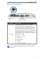
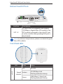
Bottom Panel Console Port
Console
Interface Description
Console
RJ45 serial console port for Command
Line Interface (CLI) management. Use an
RJ45-to-DB9, serial console cable, also known
as a rollover cable, to connect the Console
port to your computer. (If your computer does
not have a DB9 port, then you will also need
a DB9 adapter.) Then configure the following
settings as needed:
• Baud rate 115200
• Data bits 8
• Parity NONE
• Stop bits 1
• Flow control NONE
Note: Remove the protective plug from the Console port
before use.
3
Hardware Overview

Power Options
Either the VDC or PoE input type is used at any one time. If both
are connected, only the input type with the highest voltage will be
used; the other can be used as a backup.
Both PoE inputs can be used at the same time. If there is a voltage
difference, the higher-voltage source will be used first. The voltage
from the initial source will drop as the load increases. When the
voltage drops to the same level as the lower-voltage source, then
the lower-voltage source will also start providing power.
Power Input Options
• 54VDC, 6A
• 54V, 1.5A on eth0 (PoE In)
• 54V, 1.5A on PoE In
Power Output Options
• EdgePoint (required)
• Passive 54/24V, 4-Pair PoE on
eth1-eth2
• Passive 24V, 2-Pair PoE on
eth3-eth7
The number of devices that can be powered depends on the
power consumption of the specific devices. Example: If you use
54VDC, 1.5A, then you have 81W. If the EdgePoint uses 40W, then
you have 41W for PoE output. Check product specifications for the
power consumption values to use in your calculations.
Bottom Panel DC Input
VDC
Interface Description
VDC In
Terminal block connector uses auto-polarity
detection and accepts +42 to +56VDC, 6A
input (including the Ubiquiti EdgePower
™
,
model EP-54V-150W) to power the EdgePoint
and passive PoE output. -48V is NOT supported.
4
EdgePoint EP-R8 Quick Start Guide

Bottom Panel RJ45 Ports
PoE In
eth0
eth1-2
eth3-7
Interface
Description
PoE In
Accepts 54V, 1.5A PoE input from a secondary
PoE adapter (not included) to power the
EdgePoint and passive PoE output.
PoE In / eth0
Accepts data and 54V, 1.5A PoE input from
the included Gigabit PoE Adapter to power the
EdgePoint and passive PoE output.
eth1-2
(54/24V
PoE Out)
RJ45 ports support 10/100/1000 Ethernet
connections and passive 54/24V, 4-pair PoE
output for airFiber® devices.
eth3-7
(24V PoE Out)
RJ45 ports support 10/100/1000 Ethernet
connections and passive 24V, 2-pair PoE
output for airMAX® devices.
RJ45 port eth6 or eth7 is active only if the
corresponding SFP port is empty.
Note: The USB port is reserved for future use.
5
Hardware Overview

Bottom Panel SFP Ports
SFP 1-2
Interface
Description
SFP 1-2
SFP ports are hot-swappable and support
100 Mbps or Gigabit fiber SFP modules. If an
SFP module is plugged in, then the SFP port
is active, and the corresponding RJ45 port is
deactivated.
Note: For extreme temperatures, please use industrial-grade
fiber SFP modules.
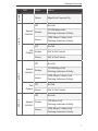
Front Panel LEDs
LED State Status
eth0
Speed/
Link/Act
Off No Link
Amber
10/100Mbps Link
Flashing Indicates Activity
Green
1000Mbps (1 Gbps) Link
Flashing Indicates Activity
6
EdgePoint EP-R8 Quick Start Guide

LED State Status
power
Green EdgePoint Powered On
eth1-2
Speed/
Link/Act
Off No Link
Amber
10/100Mbps Link
Flashing Indicates Activity
Green
1000Mbps (1 Gbps) Link
Flashing Indicates Activity
PoE
Output
Off No PoE
Amber 54V, 4-Pair Passive
Green 24V, 4-Pair Passive
eth3-7
Speed/
Link/Act
Off No Link
Amber
10/100Mbps Link
Flashing Indicates Activity
Green
1000Mbps (1 Gbps) Link
Flashing Indicates Activity
PoE
Output
Off No PoE
Green 24V, 2-Pair Passive
SFP 1-2
Speed/
Link/Act
Off No Link
Amber
100Mbps Link
Flashing Indicates Activity
Green
1000Mbps (1 Gbps) Link
Flashing Indicates Activity
7
Hardware Overview

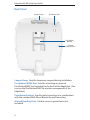
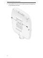
Back Panel
PicoStation Slot
Lanyard Loop
Pole-Mount
Bracket
Ground
Bonding Point
Lanyard Loop Used for temporary support during installation.
PicoStation®M2HP Slot Used for mounting an optional
PicoStationM2HP (not included) to the back of the EdgePoint. (You
can use the PicoStationM2HP for wireless management of the
EdgePoint.)
Pole-Mount Bracket Used for pole-mounting or in combination
with the included Wall-Mount Bracket for wall-mounting.
Ground Bonding Point Used to secure a ground wire (not
included).
8
EdgePoint EP-R8 Quick Start Guide

Attaching the Cable Sleeve
3. Insert and rotate the coupling to attach the Cable Sleeve to the
EdgePoint.
Note: You have two options for using a 2.0-inch NPT
(National Pipe Thread) male conduit (not included):
• Use the conduit instead of the CableSleeve.
• Use the conduit to extend the CableSleeve.
9
Attaching the Cable Sleeve

Hardware Installation
You can mount the EdgePoint on a pole or to a wall. Follow the
appropriate instructions for your installation method.
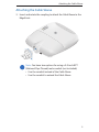
Pole-Mounting
1. Open the two Metal Straps and feed them through the
mounting slots on the back of the EdgePoint.
2. Wrap the Metal Straps around the pole. Use a 7 mm socket
wrench to turn the screws clockwise and securely fasten the
straps to the pole.
3. Proceed to the Grounding the EdgePoint section.
10
EdgePoint EP-R8 Quick Start Guide

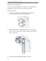
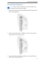
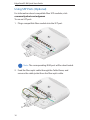
Wall-Mounting
1. Use M8 screws and anchors (not included) to attach the
Wall-Mount Bracket to the wall.
Note: The Wall-Mount Bracket must attach directly to a
stud or other structurally stablesurface.
Tab
Pointing
Up
2. Insert the tabs of the Wall-Mount Bracket into the slots of the
EdgePoint. Slide the EdgePoint down.
11
Hardware Installation

3. Use two M8x10 screws (not included) to attach the EdgePoint
to the Wall-Mount Bracket.
12
EdgePoint EP-R8 Quick Start Guide

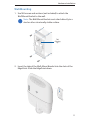
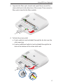
Grounding the EdgePoint
Note: The ground wire should be as short as possible and
no longer than one meter in length.
1. Remove the nut from the Ground Bonding Point located on the
back of the EdgePoint.
2. Attach a ground wire (min. 10 AWG or 5 mm
2
) to the lug and
replace the nut to secure the wire.
3. Secure the other end of the ground wire to a grounded mast,
pole, tower, or grounding bar.
13
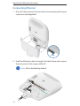
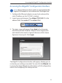
Grounding the EdgePoint

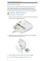
Connecting Ethernet
1. Use an S2 hex wrench to loosen the Screw and remove the port
cover from the EdgePoint.
Screw
2. Feed the Ethernet cables through the Cable Sleeve and connect
them to ports in this range: eth0-eth7.
Note: PoE is disabled by default.
14
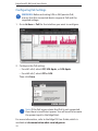
EdgePoint EP-R8 Quick Start Guide

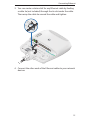
3. You can create a strain relief for any Ethernet cable by feeding
a cable tie (not included) through the tie slot under the cable.
Then wrap the cable tie around the cable and tighten.
4. Connect the other ends of the Ethernet cables to your network
devices.
15
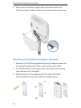
Connecting Ethernet

Using SFP Ports (Optional)
For information about compatible fiber SFP modules, visit:
community.ubnt.com/edgemax
To use an SFP port:
1. Plug a compatible fiber module into the SFP port.
Note: The corresponding RJ45 port will be deactivated.
2. Feed the fiber optic cable through the Cable Sleeve, and
remove the cable jacket from the fiber optic cable.
1000Mbps SM/SC 20KM DDM
Tx1550nm/Rx1310nm
SN: 1 308 2617 9
EF- 100 0M- 20K M- 15
50
50
50
50
16
EdgePoint EP-R8 Quick Start Guide

3. Separate the fiber optic strands and spool them around the
strain relief reels in the direction of the arrows. Then connect a
fiber optic strand to the fiber module.
50
50
50
1000Mbps SM/SC 20KM DDM
Tx1550nm/Rx1310nm
SN: 1 308 2617 9
EF- 100 0M- 20K M- 15
50
4. To finish the strain relief:
a. Feed a cable tie (not included) through the tie slot near the
cable opening.
b. Feed an additional cable tie (not included) through the tie
slots at the bottom of the strain relief reels.
50
50
50
1000Mbps SM/SC 20KM DDM
Tx1550nm/Rx1310nm
SN: 1 308 2617 9
EF- 100 0M- 20K M- 15
50
17
Using SFP Ports (Optional)

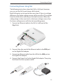
Connecting to Power
Either the +42 to +56VDC input or PoE input is used at any one
time. If both input types are connected, only the input type
with the highest voltage will be used; the other can be used as a
backup. Follow the appropriate instructions for your installation.
WARNING: -48V is NOT supported.
Connecting to the VDC Input
1. Wire one end of the DC power cable to the VDC terminal block,
which uses auto-polarity detection.
2. Replace the port cover and use an S2 hex wrench to tighten
the Screw and secure the port cover.
Screw
3. Wire the other end of the cable to a DC power supply.
4. Connect the DC power supply to its power source.
18
EdgePoint EP-R8 Quick Start Guide
Pagina se încarcă ...
Pagina se încarcă ...
Pagina se încarcă ...
Pagina se încarcă ...
Pagina se încarcă ...
Pagina se încarcă ...
Pagina se încarcă ...
Pagina se încarcă ...
Pagina se încarcă ...
Pagina se încarcă ...
Pagina se încarcă ...
Pagina se încarcă ...
Pagina se încarcă ...
Pagina se încarcă ...
Pagina se încarcă ...
Pagina se încarcă ...
-
 1
1
-
 2
2
-
 3
3
-
 4
4
-
 5
5
-
 6
6
-
 7
7
-
 8
8
-
 9
9
-
 10
10
-
 11
11
-
 12
12
-
 13
13
-
 14
14
-
 15
15
-
 16
16
-
 17
17
-
 18
18
-
 19
19
-
 20
20
-
 21
21
-
 22
22
-
 23
23
-
 24
24
-
 25
25
-
 26
26
-
 27
27
-
 28
28
-
 29
29
-
 30
30
-
 31
31
-
 32
32
-
 33
33
-
 34
34
-
 35
35
-
 36
36


Ubiquiti EdgePoint EP-R8 Quick Start Quide
- Categorie
- Convertoare media de rețea
- Tip
- Quick Start Quide
- Acest manual este potrivit și pentru
în alte limbi
- English: Ubiquiti EdgePoint EP-R8
- italiano: Ubiquiti EdgePoint EP-R8
Lucrări conexe
-
Ubiquiti Edge Point EP-R8 Ghid de inițiere rapidă
-
Ubiquiti edgepoint r6 Ghid de inițiere rapidă
-
-
-
Ubiquiti Networks Edge Pro ERPro-8 Manualul utilizatorului
-
Ubiquiti EdgeRouter X ER-X Ghid de inițiere rapidă
-
-
-
-
Ubiquiti Networks AF-24 Manualul utilizatorului