Ubiquiti EdgePower EP-54V-150W Ghid de inițiere rapidă
- Tip
- Ghid de inițiere rapidă

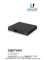
54V, 150W EdgePoint
™
DC Power Supply
Model: EP-54V-150W
Available from A1 Security Cameras
www.a1securitycameras.com email: [email protected]

Introduction
Thank you for purchasing the Ubiquiti Networks® EdgePower
™
.
This Quick Start Guide is designed to guide you through the
installation and also includes the warranty terms.
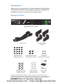
Package Contents
EdgePower EP-54V-150W
Power Cord Mount Brackets
(Qty. 4)
Bracket Screws
(M4x5.3, Qty. 16)
Rack-Mount Screws
(#10-32 x 5/8", Qty. 4)
Cage Nuts
(#10-32 x 5/8", Qty. 4)
54V, 150W EdgePoint
™
DC Power Supply
Model: EP-54V-150W
Mounting Screws
(M4x30, Qty. 8)
Screw Anchors
(M4x24, Qty. 8)
Quick Start
Guide
TERMS OF USE: All Ethernet cabling runs must use CAT5 (or above). It is the customer’s
responsibility to follow local country regulations, including operation within legal frequency
channels, output power, indoor cabling requirements, and Dynamic Frequency Selection
(DFS) requirements.
Available from A1 Security Cameras
www.a1securitycameras.com email: [email protected]

System Requirements
• Linux, MacOSX, or Microsoft Windows 7/8/10
• Web Browser: Mozilla Firefox, Google Chrome, Microsoft
Edge, or Microsoft Internet Explorer 11
Installation Requirements
• EdgePoint EP-R8 or EP-S16 (54VDC supported device)
• Phillips screwdriver (for mounting)
• Standard-sized, 19" wide rack with a minimum of 1U height
available (for rack-mounting)
• PowerCable
™
or equivalent outdoor-rated, 12 AWG stranded
DC power cable
WARNING: To reduce the risk of fire or electric shock,
do not expose the EdgePower to rain or moisture.
Note: Although the cabling can be located outdoors,
the EdgePower itself should be housed inside a
protective enclosure.
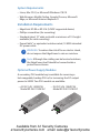
Optional Power Supply Modules
A secondary PSU module bay is available for reserving a
hot-swappable, backup PSU or for increasing the DC output
power to 300W. Two PSU models are available:
• AC/DC 54V, 150W PSU
Model EP-54V-150W-AC
• DC/DC 54V, 150W PSU
Model EP-54V-150W-DC
Available from A1 Security Cameras
www.a1securitycameras.com email: [email protected]

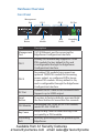
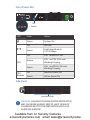
Hardware Overview
Front Panel
Reset
Button
PSU
Module
Bay
Cover
Grounding
Bolt
Management
Port
PSU 1 PSU 2 DC Out
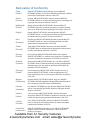
Port Description
Management
Port
10/100 Ethernet port for accessing the
EdgePower Configuration Interface.
PSU 1
Primary PSU module bay supports a 150W
PSU module. Factory default is On, and
is configurable through the EdgePower
Configuration Interface.
PSU 2
Secondary PSU module bay supports an
optional 150W PSU module for increasing
power output, or configured Off to house
a spare PSU module. Factory default is On,
and is configurable through the EdgePower
Configuration Interface.
DC Out
Connect the DC cable to this terminal block.
Supports up to 300W output.
Reset
Button
To restore to factory defaults, press and hold
the Reset button for more than five seconds.
PSU Module
Preinstalled 54V, 150W AC/DC PSU module,
model EP-54V-150W-AC.
Bay Cover
Keep the Bay Cover on when the bay is not
occupied by a PSU module.
Grounding
Bolt
Auxiliary grounding point for grounding the
EdgePower.
Available from A1 Security Cameras
www.a1securitycameras.com email: [email protected]

Front Panel LEDs
PSU
Module
LED State Status
Green System On
Off No Link
Green
Link Established at
10/100Mbps
PSU
Off PSU 1 and PSU 2 Off
Amber
PSU 1 or PSU 2 On and
Working Properly
Green
PSU 1 and PSU 2 On and
Working Properly
PSU
Module
Off Inactive, Power Off
Green Active, Power On
Side Panel
Ventilation Holes
WARNING: FAILURE TO PROVIDE PROPER VENTILATION
MAY CAUSE FIRE HAZARD. KEEP AT LEAST 20 MM OF
CLEARANCE NEXT TO THE VENTILATION HOLES FOR
ADEQUATE AIRFLOW.
Available from A1 Security Cameras
www.a1securitycameras.com email: [email protected]

Hardware Installation
The EdgePower can be placed on a horizontal surface,
rack-mounted, or mounted on a wall or shelf.
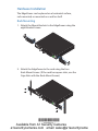
Rack Mounting
1. Attach the Mount Brackets to the EdgePower using the
eight Bracket Screws.
2. Attach the EdgePower to the rack using the four
Rack‑Mount Screws. (If the rack has square slots, use the
Cage Nuts with the Rack‑Mount Screws.)
*640-00232-01*
640-00232-01
Available from A1 Security Cameras
www.a1securitycameras.com email: [email protected]

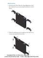
Wall Mounting
1. Attach the four Mount Brackets to the EdgePower using
the 16 Bracket Screws, positioning the brackets as shown
below.
2. Attach the EdgePower to the wall using the eight Screw
Anchors and eight Mounting Screws.
Available from A1 Security Cameras
www.a1securitycameras.com email: [email protected]

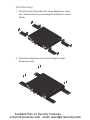
Shelf Mounting
1. Attach the four Mount Brackets to the EdgePower using
the 16 Bracket Screws, positioning the brackets as shown
below.
2. Attach the EdgePower to the shelf using the eight
Mounting Screws.
Available from A1 Security Cameras
www.a1securitycameras.com email: [email protected]

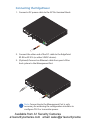
Connecting the EdgePower
1. Connect a DC power cable to the DC Out terminal block.
2. Connect the other end of the DC cable to the EdgePoint
EP-R8 or EP-S16 (or other 54VDC device).
3. (Optional) Connect an Ethernet cable from your LAN or
host system to the Management Port.
Note: Connecting to the Management Port is only
necessary for accessing the configuration interface to
configure PSU 2 or to monitor power.
Available from A1 Security Cameras
www.a1securitycameras.com email: [email protected]

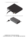
4. Connect the Power Cord to the PSU Module.
5. Connect the other end of the Power Cord to a power outlet.
Available from A1 Security Cameras
www.a1securitycameras.com email: [email protected]

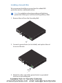
Installing a Ground Wire
We recommend installing a ground wire for added ESD
protection and asa safety precaution.
Note: For guidelines about grounding and lightning
protection, follow your local electrical regulatory codes.
1. Remove the nut from the Grounding Bolt.
2. Connect a ground wire (not included), and replace the nut
to secure the wire.
3. Attach the other end of the ground wire to a grounded
structure or grounding bar.
Available from A1 Security Cameras
www.a1securitycameras.com email: [email protected]

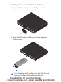
Installing a Secondary PSU Module (Optional)
1. Depress the four locking tabs on the Bay Cover and
removeit.
2. Insert the PSU module until the Lock Lever engages and
locks into place.
Lock Lever
Note: To remove a PSU module, push and hold the Lock
Lever to the left and then pull the module out.
Available from A1 Security Cameras
www.a1securitycameras.com email: [email protected]

Accessing the Configuration Interface
(Optional)
Access the EdgePower Configuration Interface to monitor
status and power consumption, or to configure the PSU
modules and network settings.
Configuration is only necessary if you have an optional PSU
module installed in the PSU 2 bay and need to deactivate it.
By default, PSU 2 is on and configured to provide additional
power output.
Note: The EdgePower is set to DHCP by default with a
fallback IP address of 192.168.10.1.
1. Connect an Ethernet cable from your host system to the
Management Port.
2. Configure the Ethernet adapter on your host system with a
static IP address on the 192.168.10.x subnet.
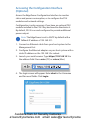
3. Launch your web browser. Type https://192.168.10.1 in
the address field. Press enter (PC) or return (Mac).
4. The login screen will appear. Enter ubnt in the Username
and Password fields. Click Login.
Available from A1 Security Cameras
www.a1securitycameras.com email: [email protected]

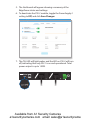
5. The Dashboard will appear showing a summary of the
EdgePower status and settings.
6. To deactivate the PSU 2 module, toggle the Power Supply 2
setting to Off, and click Save Changes.
7. The PSU LED will light amber and the LED on PSU 2 will turn
off, indicating that only PSU 1 is on and operational. Total
power output is up to 150W.
Available from A1 Security Cameras
www.a1securitycameras.com email: [email protected]

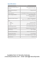
Specifications
EdgePower EP-54V-150W
Dimensions without Mount
Brackets
299.8 x 286.9 x 42.55 mm
(11.89 x 11.3 x 1.675")
Weight without Mount
Brackets
2.7 kg (5.95 lb)
Power Method 100-240VAC/50-60 Hz, Universal Input
Power Supply Module 54V, 150W AC/DC,
Model EP-54V-150W-AC,
Installed in PSU 1
Maximum Power Output 150W (1 PSU Module)
300W (2 PSU Modules @ 150W Each)
LEDs
Power
Ethernet
PSU
System On/Off
Management Port Link
PSU1+PSU2, PSU1/PSU2
Networking Interface (1) 10/100 RJ45 Ethernet
Management Interface Ethernet In-Band, Web UI
Rack-Mount Yes, 1U High
Operating Temperature 0 to 40° C (32 to 104° F)
Operating Humidity 10 to 90% RH
ESD/EMP Protection Air ± 24KV; Contact ± 24KV
Certications CE, FCC, IC
Available from A1 Security Cameras
www.a1securitycameras.com email: [email protected]

Safety Notices
1. Read, follow, and keep these instructions.
2. Heed all warnings.
3. Only use attachments/accessories specified by the manufacturer.
WARNING: Failure to provide proper ventilation may
cause fire hazard. Keep at least 20mm of clearance next
to the ventilation holes for adequate airflow.
WARNING: To reduce the risk of fire or electric shock, do
not expose this product to rain or moisture.
WARNING: Do not use this product in location that can
be submerged by water.
WARNING: Avoid using this product during an electrical
storm. There may be a remote risk of electric shock from
lightning.
Electrical Safety Information
1. Compliance is required with respect to voltage, frequency, and current
requirements indicated on the manufacturer’s label. Connection to a
different power source than those specified may result in improper
operation, damage to the equipment or pose a fire hazard if the
limitations are not followed.
2. There are no operator serviceable parts inside this equipment. Service
should be provided only by a qualified service technician.
3. This equipment is provided with a detachable power cord which has
an integral safety ground wire intended for connection to a grounded
safety outlet.
a. Do not substitute the power cord with one that is not the provided
approved type. Never use an adapter plug to connect to a 2-wire
outlet as this will defeat the continuity of the grounding wire.
b. The equipment requires the use of the ground wire as a part of the
safety certification, modification or misuse can provide a shock
hazard that can result in serious injury or death.
c. Contact a qualified electrician or the manufacturer if there
are questions about the installation prior to connecting the
equipment.
d. Protective earthing is provided by Listed AC adapter. Building
installation shall provide appropriate short-circuit backup
protection.
e. Protective bonding must be installed in accordance with local
national wiring rules and regulations.
Available from A1 Security Cameras
www.a1securitycameras.com email: [email protected]

Limited Warranty
UBIQUITI NETWORKS, Inc (“UBIQUITI NETWORKS”) warrants that the
product(s) furnished hereunder (the “Product(s)”) shall be free from defects
in material and workmanship for a period of one (1) year from the date
of shipment by UBIQUITI NETWORKS under normal use and operation.
UBIQUITI NETWORKS’ sole and exclusive obligation and liability under
the foregoing warranty shall be for UBIQUITI NETWORKS, at its discretion,
to repair or replace any Product that fails to conform to the above
warranty during the above warranty period. The expense of removal and
reinstallation of any Product is not included in this warranty. The warranty
period of any repaired or replaced Product shall not extend beyond its
original term.
Warranty Conditions
The above warranty does not apply if the Product:
(I) has been modified and/or altered, or an addition made thereto,
except by Ubiquiti Networks, or Ubiquiti Networks’ authorized
representatives, or as approved by Ubiquiti Networks in writing;
(II) has been painted, rebranded or physically modified in any way;
(III) has been damaged due to errors or defects in cabling;
(IV) has been subjected to misuse, abuse, negligence, abnormal physical,
electromagnetic or electrical stress, including lightning strikes, or
accident;
(V) has been damaged or impaired as a result of using third party
firmware;
(VI) has no original Ubiquiti MAC label, or is missing any other original
Ubiquiti label(s); or
(VII) has not been received by Ubiquiti within 30 days of issuance of
the RMA.
In addition, the above warranty shall apply only if: the product has been
properly installed and used at all times in accordance, and in all material
respects, with the applicable Product documentation; all Ethernet cabling
runs use CAT5 (or above), and for outdoor installations, shielded Ethernet
cabling is used, and for indoor installations, indoor cabling requirements
are followed.
Returns
No Products will be accepted for replacement or repair without obtaining
a Return Materials Authorization (RMA) number from UBIQUITI NETWORKS
during the warranty period, and the Products being received at UBIQUITI
NETWORKS’ facility freight prepaid in accordance with the RMA process of
UBIQUITI NETWORKS. Products returned without an RMA number will not
be processed and will be returned freight collect or subject to disposal.
Information on the RMA process and obtaining an RMA number can be
found at: www.ubnt.com/support/warranty.
Available from A1 Security Cameras
www.a1securitycameras.com email: [email protected]

Disclaimer
EXCEPT FOR ANY EXPRESS WARRANTIES PROVIDED HEREIN, UBIQUITI
NETWORKS, ITS AFFILIATES, AND ITS AND THEIR THIRD PARTY DATA,
SERVICE, SOFTWARE AND HARDWARE PROVIDERS HEREBY DISCLAIM
AND MAKE NO OTHER REPRESENTATION OR WARRANTY OF ANY KIND,
EXPRESS, IMPLIED OR STATUTORY, INCLUDING, BUT NOT LIMITED TO,
REPRESENTATIONS, GUARANTEES, OR WARRANTIES OF MERCHANTABILITY,
ACCURACY, QUALITY OF SERVICE OR RESULTS, AVAILABILITY,
SATISFACTORY QUALITY, LACK OF VIRUSES, QUIET ENJOYMENT, FITNESS
FOR A PARTICULAR PURPOSE AND NON-INFRINGEMENT AND ANY
WARRANTIES ARISING FROM ANY COURSE OF DEALING, USAGE OR
TRADE PRACTICE IN CONNECTION WITH SUCH PRODUCTS AND SERVICES.
BUYER ACKNOWLEDGES THAT NEITHER UBIQUITI NETWORKS NOR
ITS THIRD PARTY PROVIDERS CONTROL BUYER’S EQUIPMENT OR THE
TRANSFER OF DATA OVER COMMUNICATIONS FACILITIES, INCLUDING
THE INTERNET, AND THAT THE PRODUCTS AND SERVICES MAY BE
SUBJECT TO LIMITATIONS, INTERRUPTIONS, DELAYS, CANCELLATIONS
AND OTHER PROBLEMS INHERENT IN THE USE OF COMMUNICATIONS
FACILITIES. UBIQUITI NETWORKS, ITS AFFILIATES AND ITS AND THEIR THIRD
PARTY PROVIDERS ARE NOT RESPONSIBLE FOR ANY INTERRUPTIONS,
DELAYS, CANCELLATIONS, DELIVERY FAILURES, DATA LOSS, CONTENT
CORRUPTION, PACKET LOSS, OR OTHER DAMAGE RESULTING FROM ANY
OF THE FOREGOING. In addition, UBIQUITI NETWORKS does not warrant
that the operation of the Products will be error-free or that operation will
be uninterrupted. In no event shall UBIQUITI NETWORKS be responsible
for damages or claims of any nature or description relating to system
performance, including coverage, buyer’s selection of products (including
the Products) for buyer’s application and/or failure of products (including
the Products) to meet government or regulatory requirements.
Limitation of Liability
EXCEPT TO THE EXTENT PROHIBITED BY LOCAL LAW, IN NO EVENT WILL
UBIQUITI OR ITS SUBSIDIARIES, AFFILIATES OR SUPPLIERS BE LIABLE FOR
DIRECT, SPECIAL, INCIDENTAL, CONSEQUENTIAL OR OTHER DAMAGES
(INCLUDING LOST PROFIT, LOST DATA, OR DOWNTIME COSTS), ARISING
OUT OF THE USE, INABILITY TO USE, OR THE RESULTS OF USE OF THE
PRODUCT, WHETHER BASED IN WARRANTY, CONTRACT, TORT OR OTHER
LEGAL THEORY, AND WHETHER OR NOT ADVISED OF THE POSSIBILITY OF
SUCH DAMAGES.
Available from A1 Security Cameras
www.a1securitycameras.com email: [email protected]

Note
Some countries, states and provinces do not allow exclusions of implied
warranties or conditions, so the above exclusion may not apply to you.
You may have other rights that vary from country to country, state to
state, or province to province. Some countries, states and provinces do not
allow the exclusion or limitation of liability for incidental or consequential
damages, so the above limitation may not apply to you. EXCEPT TO
THE EXTENT ALLOWED BY LOCAL LAW, THESE WARRANTY TERMS DO
NOT EXCLUDE, RESTRICT OR MODIFY, AND ARE IN ADDITION TO, THE
MANDATORY STATUTORY RIGHTS APPLICABLE TO THE LICENSE OF ANY
SOFTWARE (EMBEDDED IN THE PRODUCT) TO YOU. The United Nations
Convention on Contracts for the International Sale of Goods shall not apply
to any transactions regarding the sale of the Products.
Compliance
FCC
Changes or modifications not expressly approved by the party responsible
for compliance could void the user’s authority to operate the equipment.
This device complies with Part 15 of the FCC Rules. Operation is subject to
the following two conditions:
1. This device may not cause harmful interference, and
2. This device must accept any interference received, including
interference that may cause undesired operation.
NOTE: This equipment has been tested and found to comply with the
limits for a Class A digital device, pursuant to part 15 of the FCC Rules.
These limits are designed to provide reasonable protection against
harmful interference when the equipment is operated in a commercial
environment. This equipment generates, uses, and can radiate radio
frequency energy and, if not installed and used in accordance with
the instruction manual, may cause harmful interference to radio
communications. Operations of this equipment in a residential area is likely
to cause harmful interference in which case the user will be required to
correct the interference at his own expense.
Industry Canada
CAN ICES-3(A)/NMB-3(A)
This Class A digital apparatus complies with Canadian CAN ICES-3(A).
CAN ICES-3(A)/NMB-3(A)
Cet appareil numérique de la classe A est conforme à la norme NMB-3(A)
Canada.
Available from A1 Security Cameras
www.a1securitycameras.com email: [email protected]

Australia and New Zealand
Warning: This is a Class A product. In a domestic environment this
product may cause radio interference in which case the user may
be required to take adequate measures.
CE Marking
CE marking on this product represents the product is in compliance with all
directives that are applicable to it.
RoHS/WEEE Compliance Statement
English
European Directive 2002/96/EC requires that the equipment bearing
this symbol on the product and/or its packaging must not be disposed
of with unsorted municipal waste. The symbol indicates that this
product should be disposed of separately from regular household waste
streams. It is your responsibility to dispose of this and other electric and
electronic equipment via designated collection facilities appointed by the
government or local authorities. Correct disposal and recycling will help
prevent potential negative consequences to the environment and human
health. For more detailed information about the disposal of your old
equipment, please contact your local authorities, waste disposal service, or
the shop where you purchased the product.
Deutsch
Die Europäische Richtlinie 2002/96/EC verlangt, dass technische
Ausrüstung, die direkt am Gerät und/oder an der Verpackung mit diesem
Symbol versehen ist, nicht zusammen mit unsortiertem Gemeindeabfall
entsorgt werden darf. Das Symbol weist darauf hin, dass das Produkt
von regulärem Haushaltmüll getrennt entsorgt werden sollte. Es
liegt in Ihrer Verantwortung, dieses Gerät und andere elektrische
und elektronische Geräte über die dafür zuständigen und von der
Regierung oder örtlichen Behörden dazu bestimmten Sammelstellen zu
entsorgen. Ordnungsgemäßes Entsorgen und Recyceln trägt dazu bei,
potentielle negative Folgen für Umwelt und die menschliche Gesundheit
zu vermeiden. Wenn Sie weitere Informationen zur Entsorgung Ihrer
Altgeräte benötigen, wenden Sie sich bitte an die örtlichen Behörden oder
städtischen Entsorgungsdienste oder an den Händler, bei dem Sie das
Produkt erworben haben.
Available from A1 Security Cameras
www.a1securitycameras.com email: [email protected]
Pagina se încarcă ...
Pagina se încarcă ...
Pagina se încarcă ...
Pagina se încarcă ...
-
 1
1
-
 2
2
-
 3
3
-
 4
4
-
 5
5
-
 6
6
-
 7
7
-
 8
8
-
 9
9
-
 10
10
-
 11
11
-
 12
12
-
 13
13
-
 14
14
-
 15
15
-
 16
16
-
 17
17
-
 18
18
-
 19
19
-
 20
20
-
 21
21
-
 22
22
-
 23
23
-
 24
24


Ubiquiti EdgePower EP-54V-150W Ghid de inițiere rapidă
- Tip
- Ghid de inițiere rapidă
în alte limbi
Lucrări conexe
-
Ubiquiti EdgePoint R8 Quick Start Quide
-
-
-
-
-
-
-
Ubiquiti Edge Point EP-R8 Ghid de inițiere rapidă