
Montage- und Betriebsanleitung
Installation and Operating Instructions
Instrukcja montażu i eksploatacjiInstallation and
Instrucţiuni de montaj şi exploatare
Birox 80, Birox 90, Birox 100,
Birox 150, Birox 200
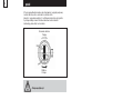
Mehrzweckpumpe
Multi-purpose pump
Pompa uniwersalna
Pompă universală
Mehr als Pumpen

2
Konformitäts-Erklärung DE
Wir Biral AG erklären in alleiniger Verantwortung,
dass die Produkte
Birox
auf die sich diese Erklärung bezieht, mit folgenden
Richtlinien des Rates zur Angleichung
der Rechtsvorschriften der EG Mitgliedstaaten
übereinstimmen:
– Maschinen (2006/42/EG)
Norm: EN 12100-1
– Elektrische Betriebsmittel zur Verwendung
innerhalb bestimmter Spannungsgrenzen
(2006/95/EG)
Normen: EN 60335-1:2002
– Elektromagnetische Verträglichkeit (2004/108/EG)
Normen: EN 61000-6-1
Declaration of Conformity EN
We Biral AG declare under our sole responsibility
that the products
Birox
to which this declaration relates, are in conformity
with the Council Directives on the approximation
of the laws of the EC Member States relating to:
– Machinery (2006/42/EC)
Standard: EN12100-1
– Electrical equipment designed for use
within certain voltage limits (2006/95/EC)
Standards: EN 60335-1:2002
– Electromagnetic compatibility (2004/108/EC)
Standards: EN 61000-6-1
Deklaracja zgodności PL
My - firma Biral - oświadczamy na własną
odpowiedzialność, że wyroby
Birox
do których odnosi się niniejsza deklaracja,
są zgodne z dyrektywami Rady w sprawie
zbliżenia
ustawodawstw Państw Członkowskich:
– Dyrektywa maszynowa UE (2006/42/EG)
Norma: EN12100-1
– Elektryczne środki pracy do stosowania
w określonych granicach napięcia (2006/95/EG)
Normy: EN 60335-1:2002
– Kompatybilność elektromagnetyczna
(2004/108/EG)
Normy: EN 61000-6 -1
Biral AG, Südstrasse 10, CH-3110 Münsingen
Phone +41(0) 31 720 90 00, Fax +41(0) 31 720 94 42
Mail: [email protected], www.biral.ch
Peter Gyger
Technical Director
Authorized representative for the completion
of the technical documentation:
Productmanager Watersupply
Südstrasse 10, CH-3110 Münsingen, Schweiz
Münsingen, 1st September 2010
Declaraţie de conformitate RO
Noi, Biral AG, declarăm pe proprie răspundere
că produsele
Birox
la care se referă această declaraţie corespund
cu următoarele Directive ale Consiliului
pentru armonizarea prevederilor legale
ale statelor membre CE:
– Utilaje (2006/42/CE)
Norma: EN 12100-1
– Echipamente electrice pentru utilizarea
în cadrul anumitor limite de tensiune (2006/95/CE)
Normele: EN 60335-1:2002
– Compatibilitate electromagnetică (2004/108/CE)
Normele: EN 61000-6-1

3
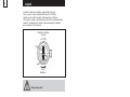
deutsch
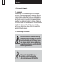
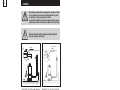
Dieses Symbol steht für Warnung vor
gefährlicher elektrischer Spannung.
«Sicherheitszeichen nach DIN 4844-W8».
Die in dieser Montage- und Betriebsanleitung
enthaltenen Sicherheitshinweise, die bei
Nicht-
beachtung Gefährdungen für Personen
hervor-
rufen können, sind mit allgemeinem Gefahren-
symbol «Sicherheitszeichen nach DIN 4844-W9»
besonders gekennzeichnet.
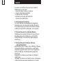
1. Sicherheitshinweise
1.1 Allgemeines
Diese Montage- und Betriebsanleitung enthält grundlegende
Hinweise, die bei Aufstellung, Betrieb und Wartung zu beachten
sind. Sie ist daher unbedingt vor Montage und Inbetriebnahme
vom Monteur sowie dem zuständigen Fachpersonal/Betreiber zu
lesen. Sie muss ständig am Einsatzort der Anlage verfügbar sein.
Es sind nicht nur die unter diesem Abschnitt «Sicherheitshinweise»
aufgeführten, allgemeinen Sicherheitshinweise zu beachten,
sondern auch die unter den anderen Abschnitten eingefügten,
speziellen Sicherheitshinweise.
1.2 Kennzeichnung von Hinweisen
Dieses Symbol finden Sie bei Sicherheits-
hinweisen, deren Nichtbeachtung Gefahren
für die Maschine und deren Funktionen
hervorrufen kann.
Achtung
Direkt an der Anlage angebrachte Hinweise wie zum Beispiel
– Drehrichtungspfeil
– Kennzeichen für Fluidanschlüsse
müssen unbedingt beachtet und in vollständig lesbarem Zustand
gehalten werden.
1.3 Personalqualifikation und -schulung
Das Personal für Montage, Bedienung, Wartung und
Inspektion
muss die entsprechende Qualifikation für diese
Arbeiten
aufweisen. Verantwortungsbereich, Zuständigkeit und die
Überwachung des Personals müssen durch den Betreiber genau
geregelt sein.
1.4 Gefahren bei Nichtbeachtung der Sicherheitshinweise
Die Nichtbeachtung der Sicherheitshinweise kann sowohl eine
Gefährdung für Personen als auch für die Umwelt und Anlage
zur Folge haben. Die Nichtbeachtung der Sicherheitshinweise
kann zum Verlust jeglicher Schadenersatzansprüche führen.

4
Im einzelnen kann Nichtbeachtung beispielsweise folgende
Gefährdungen nach sich ziehen:
– Versagen wichtiger Funktionen in der Anlage
– Versagen vorgeschriebener Methoden
zur Wartung und Instandhaltung
– Gefährdung von Personen dur
ch elektrische
und mechanische Einwirkungen
1.5 Sicherheitsbewusstes Arbeiten
Die in dieser Montage- und Betriebsanleitung aufgeführten
Sicherheitshinweise, die bestehenden nationalen Vorschriften
zur Unfallverhütung sowie eventuelle interne Arbeits-, Betriebs-
und Sicherheitsvorschriften des Betreibers, sind zu beachten.
1.6 Sicherheitshinweise für den Betreiber/Bediener
Gefährdungen durch elektrische Energie sind auszuschliessen
(Einzelheiten hierzu siehe zum Beispiel in den Vorschriften
des NIN (CENELEC) und der örtlichen Energieversorgungs-
unternehmen).
1.7 Sicherheitshinweise für Montage-, Wartungs-
und Inspektionsarbeiten
Der Betreiber hat dafür zu sorgen, dass alle Montage-, Wartungs-
und Inspektionsarbeiten von autorisiertem und qualifiziertem
Fachpersonal ausgeführt werden, das sich durch eingehendes
Studium der Montage- und Betriebsanleitung ausreichend
informiert hat.
Grundsätzlich sind Arbeiten an der Anlage nur im Stillstand
durchzuführen.
Unmittelbar nach Abschluss der Arbeiten müssen alle Sicherheits-
und Schutzeinrichtungen wieder angebracht bzw. in Funktion
gesetzt werden.
Vor der Wiederinbetriebnahme sind die im Abschnitt
«Elektrischer Anschluss» aufgeführten Punkte zu beachten.
1.8 Eigenmächtiger Umbau und Ersatzteilherstellung
Umbau oder Veränderungen an Pumpen sind nur nach Absprache
mit dem Hersteller zulässig. Originalersatzteile und vom Hersteller
autorisiertes Zubehör dienen der Sicherheit.
Die Verwendung anderer Teile kann die Haftung für die daraus
entstehenden Folgen aufheben.
1.9 Unzulässige Betriebsweisen
Die Betriebssicherheit der gelieferten Pumpen ist nur bei
bestimmungsgemässer Verwendung entsprechend Abschnitt
«Verwendungszweck» der Montage- und Betriebsanleitung
gewährleistet. Die in den technischen Daten angegebenen
Grenzwerte dürfen auf keinen Fall überschritten werden.
deutsch
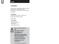
2. Transport / Lagerung
Die Pumpen werden vom Werk in einer zweckmässigen Verpackung
geliefert.

5
deutsch
3. Verwendungszweck
Die Mehrzweckpumpe aus hochwertigem rostfreiem Edelstahl,
für transportablen und stationären Einsatz, mit eingebauter
Niveausteuerung. Bei Dauerbetrieb muss die Pumpe voll mit
Förderflüssigkeit überdeckt sein.
3.1 Förderflüssigkeiten
Zur Förderung von leicht verschmutztem Wasser mit Festbestandteilen
(siehe technische Daten) ohne aggressive Beimengungen.
Einsatzgebiete
– Kellerentwässerung
– Waschküchenentwässerung
– Schacht- und Grubenentleerung
– Auspumpen von Behältern
– Grundwasserabsenkung
Die Pumpe eignet sich nicht für die Förderung von:
– Fäkalien
– Medien mit langfaserigen Bestandteilen
– Brennbaren oder explosiven Medien
(Öl, Benzin, Farbverdünner u.ä.)
– Aggressive Medien (z.B. Kondensat,
Rückspülwasser von Enthärtungsanlagen)*
– Benutzung der Pumpe in Schwimmbecken
nicht zulässig gemäss EN 60 335-2-41
– Trockenlauf nicht gestattet
–Für den Einsatz in explosionsgefährdeten
Umgebungen (ATEX)
* Hinweis: Schutzanode-Set verwenden
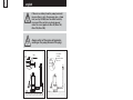
4. Installation
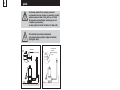
4.1 Transportabler Betrieb
Pumpe immer am Handgriff, nie am Kabel,
Druckschlauch oder Niveauschalter
tragen oder aufhängen.
– Zum Absenken in einen Schacht oder eine Grube, immer ein Seil
oder eine Kette am Handgriff befestigen
– Druckleitung: flexible, knickfreie Schlauchleitung verwenden
(Biral-Zubehör)
4.2 Stationärer Betrieb
– Pumpe auf festen und stabilen Untergrund stellen
– Druckleitung: Die feste Rohrleitung (Kunststof
fleitung)
nur von Hand in den Druckstutzen einschrauben.
Rohrleitung spannungsfr
ei montieren
– Bei Rücklauf- oder Rückstaugefahr Rückschlagklappe
und Absperrschieber in die Druckleitung einbauen
(Hinweis:
wenn möglich ausserhalb des Sammelschachtes montieren)
– Der Niveauschalter muss sich frei bewegen können

6
deutsch
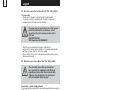
4.3 Elektrischer Anschluss Birox 80 / 90 / 100 / 150 (1×230 V)
Für Ihre Sicherheit
– Netzspannung gemäss den Angaben auf dem Typenschild
kontrollieren
– Die Pumpe ist mit dem Stecker an eine vorschriftsmässig
installierte fehlerstromgeschützte Steckdose anzuschliessen
Betrieb der Pumpe darf nur über
Fehlerstromschutzschalter erfolgen
(max. Nennauslösestromstärke
der Fehlerstromschutzschalter FI 30 mA,
DIN VDE 0100T739
SEV-Vorschrift, NIN (CENELEC)
– Bei Blockieren des Laufrades wird die Pumpe durch den eingebauten
thermischen Motorschutz ausgeschaltet. Eine Wiedereinschaltung
der Pumpe erfolgt nach Abkühlen des Motors automatisch
– Vor jeder Arbeit an der Pumpe Netzspannung ausschalten
(Stecker ziehen).
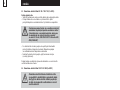
4.4 Elektrischer Anschluss Birox 100 / 150 / 200 (3× 400 V)
Der elektrische Anschluss muss von einem
Fachmann in Übereinstimmung mit den
örtlichen Vorschriften vorgenommen werden.
Achten Sie darauf, dass die auf dem Typenschild
angegebenen elektrischen Daten, mit der
vorhandenen Stromversorgung übereinstimmen.
Motorschutzschalter gemäss der
Stromaufnahme des Pumpenmotors
(siehe Typenschild am Pumpenmotor) einstellen.
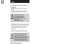
Anschluss ans Stromversorgungsnetz
Die Pumpe muss gemäss dem folgenden Schema
ans Stromversorgungsnetz angeschlossen werden.
Spannung 3×400 V
PE gelb/grün
U1 (L1)
V1 (L2)
W1 (L3)

7
deutsch
Zum Prüfen der Drehrichtung das Pumpen-Aggregat an einem Seil
oder einer Kette aufhängen und den Motor kurz laufen lassen
(einschalten und wieder ausschalten). Wenn die Drehrichtung des
Laufrades stimmt, schlägt die Pumpe im Gegenuhrzeigersinn zurück.
Die Drehrichtung kann durch Umklemmen von zwei Phasen geändert
werden.
Drehrichtung
Pumpe
Rückschlag
Pumpe
Pumpe schwenkt aus!
5. Inbetriebnahme
Betrieb der Pumpe darf nur über
Fehlerstromschutzschalter erfolgen
(max. Nennauslösestromstärke
der Fehlerstromschutzschalter 30 mA,
DIN VDE 0100T739
SEV-Vorschrift, NIN (CENELEC)
Der an der Pumpe angebaute Niveauschalter ermöglicht eine
wasserstandsabhängige automatische Ein- bzw. Ausschaltung
der Pumpe.
Die Pumpe ist nach dem Eintauchen in das Fördermedium
und dem Anschliessen an eine Steckdose sofort betriebsbereit.
Der Niveauschalter
muss sich frei bewegen können.
Achtung
Längerer Trockenlauf oder Schlürfbetrieb
ist nicht zulässig.

8
deutsch
Variante A: ohne Entlüftungsloch Variante B: mit Entlüftungsloch
Wenn die Pumpe (Variante A) nicht fördert,
weil Luft in der Druckleitung ist, muss ein Loch 3 mm
(siehe Bild 20 9940) vorsichtig gebohrt werden.
Bei der Variante B ist das Lüftungsloch bereits unter
der Abdeckung vorhanden.
(gilt für Birox 90, Birox 100, Birox 150, Birox 200)
Vor jeder Arbeit an der Pumpe Netzspannung
ausschalten (Stecker ziehen).
Markierung
Entlüftungsloch bohren
Bei Ausführung
mit Abdeckung
ist das Lüftungsloch
bereits vorhanden
6. Wartung
Die Pumpe ist wartungsfrei.
– Bei transportabler Verwendung die Pumpe nach jedem Einsatz
durch Fördern von Frischwasser reinigen, um Schmutzablagerungen
und Verkrustungen zu vermeiden.
– Bei stationärer Verwendung von Zeit zu Zeit die Funktion
des Niveauschalters überprüfen.

9
deutsch
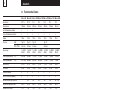
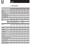
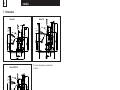
7. Abmessungen
AUS
DÉCL.
OFF
EIN
ENCL.
ON
AUS
DÉCL.
OFF
EIN
ENCL.
ON
AUS
DÉCL.
OFF
EIN
ENCL.
ON
Birox 80 Birox 90
Birox 100/150
Birox 200
Birox 100/150
* Abhängig von der Einstellung
des Schwimmerschalters
Masse in mm

20 9965.1
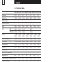
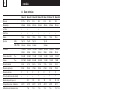
Birox 80 Birox 90 Birox 100 Birox 100 Birox 150 Birox 150 Birox 200
Anschluss R 1
1
/4 R 1
1
/2 R 2R 2R 2R 2R 2
Korngrösse 20 mm 40 mm 40 mm 40 mm 40 mm 40 mm 50 mm
mit Schwimmerschalter • • • •
ohne Schwimmerschalter • • •••••
Kabel 10 m 10 m 10 m 10 m 10 m 10 m 10 m
Stecker SEV Typ 12 Typ 12 Typ 12 Typ 12
VDE, ÖVE Schuko Schuko Schuko Schuko
Spannung 1×230 V 1×230 V 1×230 V 3×400 V 1×230 V 3×400 V 3×400 V
50 Hz 50 Hz 50 Hz 50 Hz 50 Hz 50 Hz 50 Hz
Leistungsaufnahme P
1 = 0,5 kW 0,9 kW 1,3 kW 1,3 kW 1,6 kW 1,6 kW 1,8 kW
Leistungsabgabe P2 = 0,37 kW 0,6 kW 0,9 kW 0,9 kW 1,2 kW 1,2 kW 1,3kW
Nennstrom 2,5 A 4,1 A 5,8 A 2,2 A 7,2 A 2,5 A 3,0 A
Schutzart IP 68 IP 68 IP 68 IP 68 IP 68 IP 68 IP 68
Isolationsklasse F F FFFFF
Motorschutz (eingebaut) • • •
1)
•
1) 1)
Anzahl Anläufe pro Stunde 30 30 30 30 30 30 30
Mediumtemperatur max. 40 °C 40 °C 40 °C 40 °C 40 °C 40 °C 40 °C
Eintauchtiefe max. 7 m 7 m 7 m 7 m 7 m 7 m 7 m
Gewicht 7 kg 8,5 kg 9 kg 9 kg 10 kg 10 kg 12,6 kg
1)
Motorschutz bauseits
deutsch
10
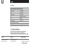
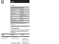
8. Technische Daten
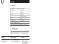
1 Kunststoffschlauch Birox 80: Nr. 05 3591.2699 (1
1
/
4
”)
Birox 90: Nr. 05 3591.3999 (1
1
/
2
”)
Birox 100/150/200: Nr. 05 3591.4199 (2”)
2 Schlauchbride Birox 80: Nr. 05 2351.0700
Birox 90: Nr. 05 2351.0800
Birox 100/150/200: Nr. 05 2351.1000
3 Anschlussbogen Birox 80: Nr. 05 3775.3862 (1
1
/
4
”)
Birox 90: Nr. 05 3775.3962 (1
1
/
2
”)
Birox 100/150/200: Nr. 05 3775.4199 (2”)
3
1
2
8.1 Zubehör

Störung Mögliche Ursache Behebung
Die Pumpe fördert kein Wasser, 1. Fehlen von Spannung im Netz
der Motor dreht nicht 2. Stecker schlecht eingesteckt 2. Prüfen ob Spannung
im Netz ist und Stecker
gut eingesteckt ist
3. Fehlerstromschutzschalter 3. Fehlerstromschutzschalter
hat ausgelöst einschalten. Falls dieser
wieder auslöst einen
Elektriker aufsuchen
4. Laufrad blockiert 4. Laufrad von möglichen
Behinderungen befreien
5. Beschädigung des Motors 5. Wiederverkäufer
oder des Kondensators benachrichtigen
6. Schwimmer schaltet nicht ein 6. Schwimmer anheben auf
Stellung «EIN» (s. Seite 9).
Schwimmer auf und ab
bewegen bis Pumpe
einschaltet
Die Pumpe fördert kein Wasser, 1. Filter verstopft 1. Filter reinigen
der Motor dreht 2. Rohrleitung verstopft 2. Verstopfung beheben
3. Laufrad abgenutzt 3. Laufrad ersetzen
Die Pumpe fördert 1. Filter teilweise verschmutzt 1. Fremdkörper entfernen
eine berenzte Wassermenge 2. Rohrleitung verstopft 2. Verstopfung beheben
3. Laufrad abgenutzt 3. Laufrad ersetzen
Unstetige Funktion 1. Festkörper verhindern die freie 1. Fremdkörper entfernen
(einphasige Ausführung) die freie Rotation des Laufrads
2. Temperatur der Flüssigkeit zu hoch 2. Medientemperatur
40° C zulässig
3. Defekter Motor 3. Wiederverkäufer
benachrichtigen
Birox 80 / Birox 90 / Birox 100 / Birox 150 / Birox 200
Pumpengehäuse Aisi 304 (V2A)
Laufrad Aisi 304 (V2A)
Motorgehäuse Aisi 304 (V2A)
Welle X2CrNiMo17132 1.4404
Kabel HO7 RNF
Schwimmerschalter Neoprene / PPH
Technische Änderungen vorbehalten
Kennlinien gelten für sauberes Wasser bei 20 °C, Tolereanz ±10%
deutsch
11
8.2 Werkstoffe
9. Störungssuche
Unter normalen Betriebsbedingungen haben Biral-Pumpen keinen
Wartungsbedarf. Gelegentlich kann es notwendig werden, den
hydraulischen Teil zu reinigen oder das Laufrad auszuwechseln.

1. Safety information
1.1 General remarks
These installation and operating instructions contain items
of information of fundamental importance which must be taken
into account during assembly, operation and maintenance.
They should therefore be read without fail before installation
and commissioning by the fitter and also the responsible
specialist staff/operator. They must always be available
for consultation at the plant’s place of deployment.
Not only are the general safety hints included in this «Safety Hints»
section to be observed, but also the special items of safety
information included in the other sections.
1.2 Identification of notices
Information signs mounted directly on the plant, such as,
for example
- arrow indicating direction of rotation
- symbols for fluid connections
must be obeyed without fail and be kept in a fully legible state.
1.3 Staff qualification and training
The staff deployed for assembly, operating, maintenance
and inspection tasks must show that they have the appropriate
qualifications for such work. The field of responsibility,
competence and supervision of the staff must be stipulated
exactly by the operator.
1.4 Risks in the event of non-compliance
with the safety information
Non-compliance with the safety information can result in both
danger for persons and also for the plant and the environment.
Non-compliance with the safety information can lead to the loss
of claims for damages of any kind.
This symbol is a warning of dangerous
electric voltage.
«Safety sign according to DIN 4844-W8».
The safety information contained in these
instal
lation and operating instructions,
non-compliance
with which can lead
to danger for people, are specially marked
with the general danger symbol
«Safety sign according to DIN 4844-W9».
You will find this symbol in the case of safety
information non-compliance with which
can endanger the machine and its functions.
Warning
english
12

2. Transport/storage
The pumps are delivered ex works in suitable packaging.
Pumps with electronic components must
be protected from moisture.
Warning
13
In detail, non-compliance, for example, may result
in the following risks:
- failure of important functions in the plant
- failure of prescribed methods for servicing and maintenance
- danger to persons through electrical and mechanical causes
1.5 Safety-conscious work
The safety information contained in these installation and
operating instructions, the existing national regulations
for the prevention of accidents, as well as any internal working,
operating and safety regulations stipulated by the operator
must be observed.
1.6 Safety information for the operator/operating personnel
Any risks from electric power must be eliminated (For details see,
for example, the regulations published by NIN (CENELEC)
and the I.E.E.).
1.7 Safety information for installation, maintenance
and inspection works
The operator has to ensure that all installation, maintenance
and inspection works are carried out by authorised and qualified
specialist personnel who have informed themselves adequately
about the requirements by a thorough study of the installation
and operating instructions.
Basically, any works on the plant should only be carried out
when it is at a standstill and not carrying any electrical current.
Directly after completion of the works, all safety and protective
installations must be mounted or activated again.
Before re-commissioning, the points listed in the section
«Electrical connection» must be observed.
1.8 Unauthorised reconstruction and production of spares
Reconstruction of or changes to pumps are only permissible
after consultation with the manufacturer. Genuine spare parts
and accessories authorised by the manufacturer serve the cause
of safety.
The use of other parts can cancel any liability for the resultant
consequences of this.
1.9 Improper operating methods
The operating reliability of the pumps supplied is only guaranteed
with appropriate application of the section «Intended application»
of the Installation and Operating Instructions. The limit values
given in the technical data must not be exceeded on any account.
english

14
english
3. Intended applications
The multi-purpose pump is made of high-quality stainless steel,
intended for mobile and stationary use and equipped
with a built-in level control. For continuous operation the pump
must be fully covered with the feed liquid!
3.1 Liquids delivered
For delivering slightly dirty water with solid components
(see Technical Data) without aggressive impurities.
Fields of use
– Draining cellars
– Draining laundries
– Emptying shafts and pits
– Pumping out containers
– Lowering the level of groundwater
The pump is not suitable for delivering:
– Faeces
– Media containing long fibres
– Flammable or explosive media
(oil, petrol, paint thinners, etc.)
– Aggressive Media (e.g. condensation,
backwash water from softening systems)*
– Use of the pump in swimming pools is not
permissible according to EN 60 335-2-41
– Dry running is not permitted
– For installation in an explosive environment
(ATEX)
* Note: use anode protection set
4. Installation
4.1 Mobile operation
Always carry or suspend the pump by the handle
and never by the cable, pressure hose or level switch.
– To lower the pump into a shaft or pit, always fasten a rope
or a chain to the handle
– Pressure line: use a flexible, bend-free hosepipe (Biral accessory)
4.2 Stationary operation
– Place the pump on the bottom of the shaft
– Pressure line: the fixed pipeline (plastic pipe) should be screwed
into the pressure connections only by hand.
Mount the pipeline without tension, if necessary use a hose adapter
– Install a non-return valve in the pressure line if there
is a danger of back-flow or backup
– The level switch must be capable of moving freely

15
english
4.3 Electrical connection for Birox 80 / 90 / 100 / 150 (1×230 V)
For your safety
– Check mains voltage by comparing with the rating plate
– The pump should be connected with the plug to a properly
installed socket with fault current protection
The pump may be operated only via a fault current
protection switch (max. rated release current
strength of the fault current protection switch
FI 30 mA
DIN VDE 0100T739
SEV Regulation, NIN (CENELEC)
– When the rotor is blocked, the pump is switched off
by the built-in thermal motor protection. The pump automatically
switches on again after the motor has cooled.
– Always switch off the mains voltage before working on the pump
(disconnect the plug).
4.4 Electrical connection of Birox 100 / 150 / 200 (3× 400 V)
The electrical connection must be made
by a specialist in compliance with the local
regulations. Ensure that the electrical data
stated on the rating plate is in agreement
with the available power supply:
Set the motor protection switch according
to the current consumption of the pump
motor (see rating plate on pump motor).
Connection to power supply network
The pump must be connected to the power supply network according
to the following diagram.
Voltage 3×400 V
PE yellow/green
U1 (L1)
V1 (L2)
W1 (L3)

16
english
To test the direction of rotation, suspend the pump unit
from a rope or a chain and allow the motor to run briefly
(switch on and switch off again). If the direction of rotation
of the rotor is correct, the pump kicks back in the counterclockwise
direction. The direction of rotation can be changed by changing
the connections of two phases.
Direction of rotation
of pump
Pump
kick-back
Pump swings out!
5. Commissioning
The pump may be operated only via
a fault current protection switch
(max. rated release current strength
of the fault current protection switch 30 mA
SEV Regulation, NIN (CENELEC)
The level switch mounted on the pump allows the pump to be
switched on and off automatically depending on the water level.
After immersion in the medium to be delivered and connection
to a socket, the pump is immediately ready for operation
The level switch must be capable
of moving freely.
Important
Long periods of dry running or operation
with insufficient medium are not permissible.

17
english
Version A: without vent hole Version B: with vent hole
If there is no delivery from the pump (version A)
because there is air in the pressure pipe, a 3 mm
hole (see fig. 20 9940) must be drilled carefully.
In version B the vent hole is already present
under the cover (applies to Birox 90, Birox 100,
Birox 150, Birox 200).
Always switch off the mains voltage before
working on the pump (disconnect the plug).
Mark
Drill vent hole
The vent hole
is already
present in versions
with cover.
6. Maintenance
The pump is maintenance-free.
– During mobile use, clean the pump by delivering fresh water each
time after use, in order to avoid dirt deposits and crusts.
– During stationary use, check the functioning of the level switch
from time to time.

18
english
7. Dimensions
AUS
DÉCL.
OFF
EIN
ENCL.
ON
AUS
DÉCL.
OFF
EIN
ENCL.
ON
AUS
DÉCL.
OFF
EIN
ENCL.
ON
Birox 80 Birox 90
Birox 100/150
Birox 200
Birox 100/150
* Dependent on setting
of float switch
Dimensions in mm

20 9965.1
Birox 80 Birox 90 Birox 100 Birox 100 Birox 150 Birox 150 Birox 200
Connection R 1
1
/4 R 1
1
/2 R 2R 2R 2R 2R 2
Granular size 20 mm 40 mm 40 mm 40 mm 40 mm 40 mm 50 mm
with float switch • • • •
without float switch • • • • • • •
Cable 10 m 10 m 10 m 10 m 10 m 10 m 10 m
Plug SEV Typ 12 Typ 12 Typ 12 Typ 12
VDE, ÖVE Schuko Schuko Schuko Schuko
Voltage 1×230 V 1×230 V 1×230 V 3×400 V 1×230 V 3×400 V 3×400 V
50 Hz 50 Hz 50 Hz 50 Hz 50 Hz 50 Hz 50 Hz
Power consumption P
1 = 0,5 kW 0,9 kW 1,3 kW 1,3 kW 1,6 kW 1,6 kW 1,8 kW
Power output P2 = 0,37 kW 0,6 kW 0,9 kW 0,9 kW 1,2 kW 1,2 kW 1,3kW
Nominal current 2,5 A 4,1 A 5,8 A 2,2 A 7,2 A 2,5 A 3,0 A
Protection IP 68 IP 68 IP 68 IP 68 IP 68 IP 68 IP 68
Isolation class F F F F F F F
Motor protection (mounted) • • •
1)
•
1) 1)
Max starts/hour 30 30 30 30 30 30 30
Permissible water temperature max.
40 °C 40 °C 40 °C 40 °C 40 °C 40 °C 40 °C
Immersion depth max. 7 m 7 m 7 m 7 m 7 m 7 m 7 m
Weight 7 kg 8,5 kg 9 kg 9 kg 10 kg 10 kg 12,6 kg
1)
Motor protection by customer
english
19
8. Technical data
1 Synthetic hose Birox 80: Nr. 05 3591.2699 (1
1
/
4
”)
Birox 90: Nr. 05 3591.3999 (1
1
/
2
”)
Birox 100/150/200: Nr. 05 3591.4199 (2”)
2 Hose band clip Birox 80: Nr. 05 2351.0700
Birox 90: Nr. 05 2351.0800
Birox 100/150/200: Nr. 05 2351.1000
3 Connection bend Birox 80: Nr. 05 3775.3862 (1
1
/
4
”)
Birox 90: Nr. 05 3775.3962 (1
1
/
2
”)
Birox 100/150/200: Nr. 05 3775.4199 (2”)
3
1
2
8.1 Accessoires

Fault Possible cause Remedy
Pump does not deliver, 1. No electric current supplying
Motor does not run 2. Incorrect plupping in 2. Verify presence of electric
current supply and plug in
3. Circuit-breaker come into 3. Reinforce circuit-breaker.
operation Please call electrician
in case circuit-breaker
comes again into operation
4. Impeller blocked 4. Remove obstacles
5. Motor or capacitor damaged 5. Call dealer
6. Float switch does not switch on 6. Raise float switch to «ON»
position (see page 18).
Move float switch up
and down until pump
switches on.
Pump does not deliver, 1. Filter obstructed 1. Clean filter
Motor runs 2. Non return valve blocked 2. Clean or replace valve
3. Air in delivery pipe 3. Drill hole 3 mm dia.
(see fig. page 35)
Pump delivers reduced water 1. Filter partially obstructed 1. Clean filter
2. Delivery pipe partially obstructed 2. Remove obstacles
3. Impeller worn off 3. Replacer impeller
Intermittent working 1. Solids obstruct impeller 1. Remove obstacles
2. Too warm liquid 2. Max. liquid temperature
40° C
3. Defekter Motor 3. Call dealer
Birox 80 / Birox 90 / Birox 100 / Birox 150 / Birox 200
Pump casing Aisi 304 (V2A)
Impeller Aisi 304 (V2A)
Motor casing Aisi 304 (V2A)
Shaft X2CrNiMo17132 1.4404
Cable HO7 RNF
Float switch Neoprene / PPH
Subject to technical changes
Characteristic curves valid for clean water at 20 °C, tolerance ±10%
english
20
8.2 Materials
9. Trouble shooting
No maintenance is required when Birox range pumps operate
in normal conditions. Occasionally maintenance of liquid ends
and replacement of impeller may be required.
Pagina se încarcă...
Pagina se încarcă...
Pagina se încarcă...
Pagina se încarcă...
Pagina se încarcă...
Pagina se încarcă...
Pagina se încarcă...
Pagina se încarcă...
Pagina se încarcă...
Pagina se încarcă...
Pagina se încarcă...
Pagina se încarcă...
Pagina se încarcă...
Pagina se încarcă...
Pagina se încarcă...
Pagina se încarcă...
Pagina se încarcă...
Pagina se încarcă...
Pagina se încarcă...
Pagina se încarcă...
-
 1
1
-
 2
2
-
 3
3
-
 4
4
-
 5
5
-
 6
6
-
 7
7
-
 8
8
-
 9
9
-
 10
10
-
 11
11
-
 12
12
-
 13
13
-
 14
14
-
 15
15
-
 16
16
-
 17
17
-
 18
18
-
 19
19
-
 20
20
-
 21
21
-
 22
22
-
 23
23
-
 24
24
-
 25
25
-
 26
26
-
 27
27
-
 28
28
-
 29
29
-
 30
30
-
 31
31
-
 32
32
-
 33
33
-
 34
34
-
 35
35
-
 36
36
-
 37
37
-
 38
38
-
 39
39
-
 40
40


Biral Birox 80 Installation And Operating Instructions Manual
- Tip
- Installation And Operating Instructions Manual
în alte limbi
- polski: Biral Birox 80
- Deutsch: Biral Birox 80
Alte documente
-
Pentair U5 K Manual de utilizare
-
Graphite 59G446 Manualul proprietarului
-
Kärcher SP 5 Dual Submersible Dirty Water Pump Manual de utilizare
-
Vonroc SP507AC Manual de utilizare
-
Rothenberger Solar filling pump ROSOLAR Pump Manual de utilizare
-
Alfred Kärcher GmbH SP 5 Dual (1.645-580.0) Manual de utilizare
-
Milwaukee M18 BTP Original Instructions Manual
-
T.I.P. HWW 6000 INOX NIM TLS Operating Instructions Manual
-
-
Gardena 4100 Silent Garden Pump Manualul proprietarului