
DOC022.98.80554
PTM450
03/2016, Edition 1
User Manual
Bedienungsanleitung
Manuale utente
Manuel d'utilisation
Manual del usuario
Manual do utilizador
Návod k použití
Brugsanvisning
Gebruikershandleiding
Instrukcja obsługi
Bruksanvisning
Käyttäjän käsikirja
Ръководство на потребителя
Használati útmutató
Manual de utilizare
Kullanım Kılavuzu
Návod na obsluhu
Navodila za uporabo
Korisnički priručnik
Εγχειρίδιο χρήσης

English..............................................................................................................................3
Deutsch.......................................................................................................................... 11
Italiano............................................................................................................................ 19
Français......................................................................................................................... 27
Español.......................................................................................................................... 35
Português...................................................................................................................... 43
Čeština........................................................................................................................... 51
Dansk..............................................................................................................................59
Nederlands....................................................................................................................67
Polski.............................................................................................................................. 75
Svenska......................................................................................................................... 83
Suomi..............................................................................................................................91
български..................................................................................................................... 99
Magyar......................................................................................................................... 107
Română....................................................................................................................... 115
Türkçe...........................................................................................................................123
Slovenský jazyk......................................................................................................... 131
Slovenski..................................................................................................................... 139
Hrvatski........................................................................................................................ 147
Ελληνικά...................................................................................................................... 155
2

Table of contents
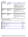
Specifications on page 3 Maintenance on page 9
General information on page 3 Troubleshooting on page 10
Installation on page 5 Replacement parts and accessories on page 10
Operation on page 8
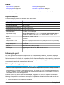
Specifications
Specifications are subject to change without notice.
Specification Details
Dimensions (W x H x D) 110 x 45 x 60 mm (4.33 x 1.77 x 2.36 in.)
Weight approximately 250 g (0.55 lb)
Operating temperature 15 to 35 °C (59 to 95 °F)
Storage temperature –5 to 40 °C (23 to 104 °F)
Relative humidity 20 to 80%, non-condensing
Power requirements Instrument input: 24 VDC 0.2 mA; External plug-in power supply: Input,
100–240 VAC, 50-60 Hz, 1.5 A, Class I; output, 24 VDC, 2.5 A
Output
1
Minimum 20 mV; maximum 1250 mV
Impedance 10 kOhms
Wavelengths 3-position switch: 525 nm ±10 nm (green); 610 nm ±10 nm (red); OFF
Response time < 1 second
Connections Local BNC cable, 1.20 m (3.94 ft)
Certifications Safety: IEC/EN 61010-1; EMC: IEC/EN 61326-1
Warranty 1 year (EU: 2 years)
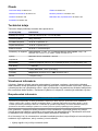
General information
In no event will the manufacturer be liable for direct, indirect, special, incidental or consequential
damages resulting from any defect or omission in this manual. The manufacturer reserves the right to
make changes in this manual and the products it describes at any time, without notice or obligation.
Revised editions are found on the manufacturer’s website.
Safety information
N O T I C E
The manufacturer is not responsible for any damages due to misapplication or misuse of this product including,
without limitation, direct, incidental and consequential damages, and disclaims such damages to the full extent
permitted under applicable law. The user is solely responsible to identify critical application risks and install
appropriate mechanisms to protect processes during a possible equipment malfunction.
Please read this entire manual before unpacking, setting up or operating this equipment. Pay
attention to all danger and caution statements. Failure to do so could result in serious injury to the
operator or damage to the equipment.
Make sure that the protection provided by this equipment is not impaired. Do not use or install this
equipment in any manner other than that specified in this manual.
1
The signal output is not sensitive to daylight.
English 3

Use of hazard information
D A N G E R
Indicates a potentially or imminently hazardous situation which, if not avoided, will result in death or serious injury.
W A R N I N G
Indicates a potentially or imminently hazardous situation which, if not avoided, could result in death or serious
injury.
C A U T I O N
Indicates a potentially hazardous situation that may result in minor or moderate injury.
N O T I C E
Indicates a situation which, if not avoided, may cause damage to the instrument. Information that requires special
emphasis.
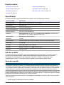
Precautionary labels
Read all labels and tags attached to the instrument. Personal injury or damage to the instrument
could occur if not observed. A symbol on the instrument is referenced in the manual with a
precautionary statement.
This is the safety alert symbol. Obey all safety messages that follow this symbol to avoid potential
injury. If on the instrument, refer to the instruction manual for operation or safety information.
This symbol indicates that a risk of electrical shock and/or electrocution exists.
Electrical equipment marked with this symbol may not be disposed of in European domestic or public
disposal systems. Return old or end-of-life equipment to the manufacturer for disposal at no charge to
the user.
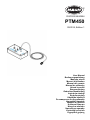
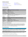
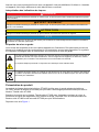
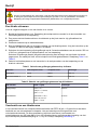
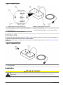
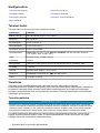
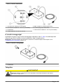
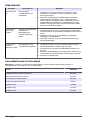
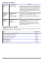
Product overview
The PTM450 is a photo-colorimetric titration module used with the OPT300 photo-colorimetric probe.
Use the module and the probe to do photo-colorimetric titrations with the Titralab AT1000 series
titrator.
Connect the module to the Titralab AT1000 series titrator with the legacy adapter and follow the
application working procedure to complete a titration. Refer to the AT1000 series titatror and
OPT3000 probe documentation for additional information.
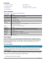
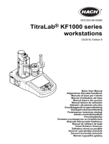
Refer to Figure 1.
4
English

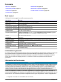
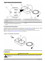
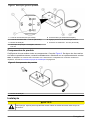
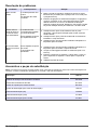
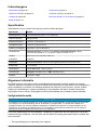
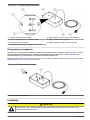
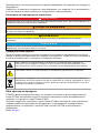
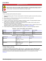
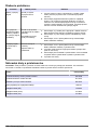
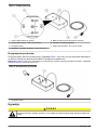
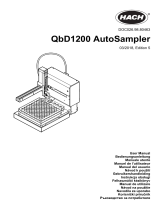
Figure 1 Product overview
1 LED in connector (from probe) 5 BNC connector (to titration system)
2 LED out connector—525 nm (from probe) 6 External power supply connection
3 Titration module 7 LED out connector—610 nm (from probe)
4 3-position switch: Off, 525 nm, 610 nm
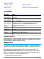
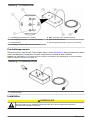
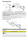
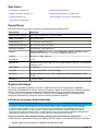
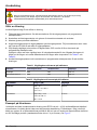
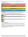
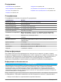
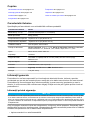
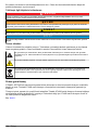
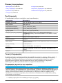
Product components
Make sure that all components have been received. Refer to Figure 2. If any items are missing or
damaged, contact the manufacturer or a sales representative immediately.
Note: The power adapter is not supplied with the instrument. The power adapter is sold separately. Refer to
Replacement parts and accessories on page 10.
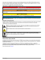
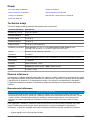
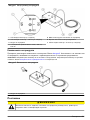
Figure 2 Product components
1 Titration module
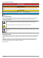
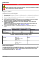
Installation
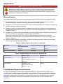
C A U T I O N
Multiple hazards. Only qualified personnel must conduct the tasks described in this section of the
document.
English 5

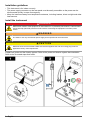
Installation guidelines
• This instrument is for indoor use only.
• The power supply connector on the rear panel must be easily accessible so the power can be
disconnected quickly in case of emergency.
• Keep the instrument away from temperature extremes, including heaters, direct sunlight and other
heat sources.
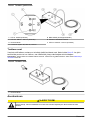
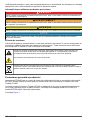
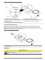
Install the instrument
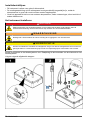
D A N G E R
Electrocution hazard. If this equipment is used outdoors or in potentially wet locations, a Ground Fault
Circuit Interrupt (GFCI/GFI) device must be used for connecting the equipment to its main power
source.
W A R N I N G
Fire hazard. Use only the external power supply that is specified for this instrument.
C A U T I O N
Electrical shock and fire hazards. Make sure that the supplied cord and non‐locking plug meet the
applicable country code requirements.
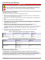
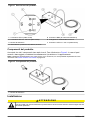
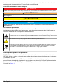
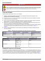
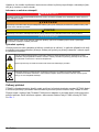
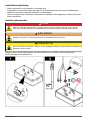
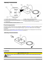
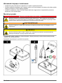
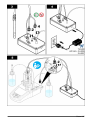
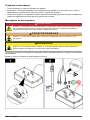
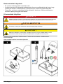
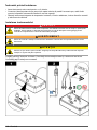
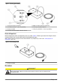
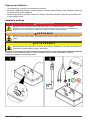
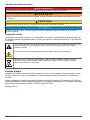
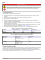
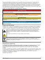
Prepare the probe and the titration system. Refer to the probe and titration system documentation.
Refer to the illustrated steps that follow.
6 English

English 7

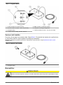
Operation
D A N G E R
Chemical exposure hazard. Obey laboratory safety procedures and wear all of the personal protective
equipment appropriate to the chemicals that are handled. Refer to the current safety data sheets
(MSDS/SDS) for safety protocols.
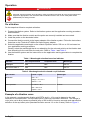
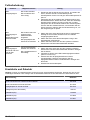
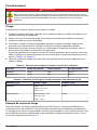
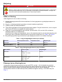
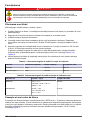
Do a titration
Do the steps that follow to complete a titration.
1. Prepare the titration system. Refer to the titration system and the application working procedure
documentation.
2. Make sure that the titration module and the probe are correctly installed and connected.
3. Install the probe on the electrode holder.
4. Connect the titration module to the legacy adapter of the titration system. Follow the instructions
that show on the TitraLab AT1000 to set up the legacy adapter.
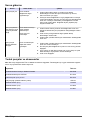
5. Select the applicable wavelength on the module 3-position switch: 525 nm or 610 nm based on
your application working procedure.
Usually, select the wavelength that is non-absorbing for the coloured solution at the titration start
then absorbing for the color after the end point. Refer to Table 1 and Table 2.
6. Use the titration system and the instructions on the application working procedure to complete the
titration.
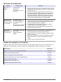
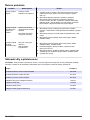
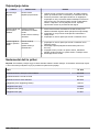
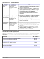
Table 1 Wavelength selection based on indicator
Indicator Non complexed form Complexed form Wavelength
Calmagite Red Blue 610 nm
Eriochrome black T Red Blue 610 nm
Table 2 Wavelength selection based on pH indicator
pH indicator Colour = f (pH) Wavelength
Helianthin red = <3.1
orange = 3.1 to 4.4
yellow = > 4.4
525 nm
Phenolphtalein no colour = <8.3
pink = 8.3 to 10
purple = >10.0
610 nm
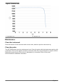
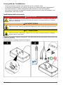
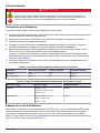
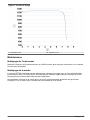
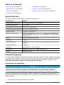
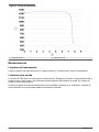
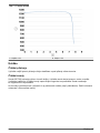
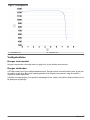
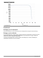
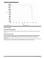
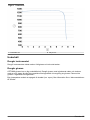
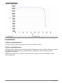
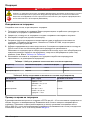
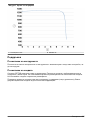
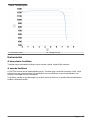
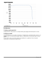
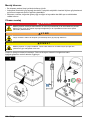
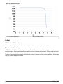
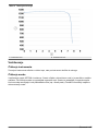
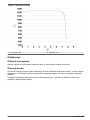
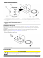
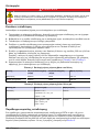
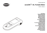
Example of a titration curve
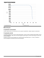
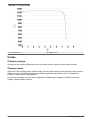
In the example, complexometric titration with EDTA at pH = 10 is used to determine the total
hardness of a mineral water. The equivalent point is find with colorimetric detection. The change in
color (wine red to blue) causes a potential jump of 600 to 800 mV and an accurate and reproducible
definition of the equivalent point (standard deviation around 1% on the 3 tests). Refer to Figure 3.
8
English

Figure 3 Titration curve
1 Potential in mV 2 Volume in mL
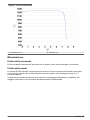
Maintenance
Clean the instrument
Clean the exterior of the instrument with a moist cloth, and then wipe the instrument dry.
Clean the probe
The OPT3000 probe has a low maintenance level. Clean the probe with deionised water and dry with
a soft tissue. Do not use organic solvents to clean the probe. Do not put the probe in organic solvent.
Replace the probe tip only if the mirror is damaged (e.g, scratches). Refer to the probe
documentation for additional information.
English
9

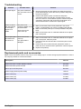
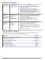
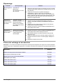
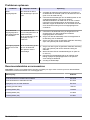
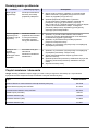
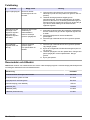
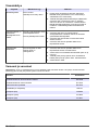
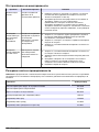
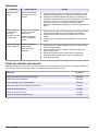
Troubleshooting
Problem Possible cause Solution
No output signal The probe is defective.
The connections are not
correct.
1. Remove the probe from the solution and make sure that the
probe transmits light (red for the 610 nm position and green for
the 525 nm position).
2. Examine the titration system connections and power
connections. Make sure that the 3-position switch is set to
525 nm or 610 nm. On the titration system, examine the probe
connection. Disconnect and connect the probe again. Do a
direct measurement to examine the output signal.
There is noise in
the output signal
or the output
signal is not
stable
The probe is not
correctly installed on the
electrode holder.
There is dirt on the
probe mirror tip.
1. Make sure that the probe is firmly attached in the sensor
holder. A small vibration can cause not stable output signals.
2. Make sure that the probe tip is correctly installed in the probe
body.
3. Make sure that there are no unwanted materials in the optical
path of the probe.
The output signal
decreases and
becomes low
There is dirt on the
probe tip.
The optical fibre is
damaged.
1. Make sure that there are no unwanted materials in the optical
path of the probe. Clean the probe.
2. Interchange the two LED Out fibre connections (525 nm and
610 nm).
3. Examine the mirror surface and the optical fibre. Clean or
polish the mirror surface and the optical fibre. Clean the probe.
4. Replace the probe tip.
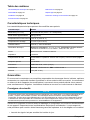
Replacement parts and accessories
Note: Product and Article numbers may vary for some selling regions. Contact the appropriate distributor or refer to
the company website for contact information.
Description Item no.
Photocolorimetric Titration Module PTM450 X61T005
Photocolorimetric probe OPT300 E71T001
Mirror tip for OPT300 probe E91T001
Power supply (without power cable) LZE144
Power cable (EU) YAA080
Power cable (US) XLH055
Power cable (UK) XLH057
10 English

Inhaltsverzeichnis
Technische Daten auf Seite 11 Wartung auf Seite 17
Allgemeine Informationen auf Seite 11 Fehlerbehebung auf Seite 18
Installation auf Seite 13 Ersatzteile und Zubehör auf Seite 18
Durchführung einer Messung auf Seite 16
Technische Daten
Änderungen vorbehalten.
Technische Daten Details
Größe (B x H x T) 110 mm x 45 mm x 60 mm (4.33 x 1.77 x 2.36 Zoll)
Gewicht (ca.) 250 g (0.55 lb)
Betriebstemperatur 15 bis 35 °C (59 bis 95 °F)
Lagerungstemperatur –5 bis 40 °C (23 bis 104 °F)
Relative Luftfeuchtigkeit 20 bis 80 %, nicht kondensierend
Stromversorgung Geräteeingang: 24 VDC, 0,2 mA; Externes Steckernetzteil: Eingang: 100-240 VAC,
50-60 Hz, 1,5 A, Klasse I; Ausgang: 24 VDC, 2,5 A
Ausgang
1
Minimal 20 mV; maximal 1250 mV
Impedanz 10 kOhm
Wellenlängen Dreistufiger Schalter: 525 nm ±10 nm (grün); 610 nm ±10 nm (rot); AUS
Ansprechzeit < 1 Sekunden
Anschlüsse Lokales BNC-Kabel, 1.20 m (3.94 ft)
Zertifizierungen Sicherheit: IEC/EN 61010-1; EMC: IEC/EN 61326-1
Garantie 1 Jahr (EU: 2 Jahre)
Allgemeine Informationen
Der Hersteller ist nicht verantwortlich für direkte, indirekte, versehentliche oder Folgeschäden, die
aus Fehlern oder Unterlassungen in diesem Handbuch entstanden. Der Hersteller behält sich
jederzeit und ohne vorherige Ankündigung oder Verpflichtung das Recht auf Verbesserungen an
diesem Handbuch und den hierin beschriebenen Produkten vor. Überarbeitete Ausgaben der
Bedienungsanleitung sind auf der Hersteller-Webseite erhältlich.
Sicherheitshinweise
H I N W E I S
Der Hersteller ist nicht für Schäden verantwortlich, die durch Fehlanwendung oder Missbrauch dieses Produkts
entstehen, einschließlich, aber ohne Beschränkung auf direkte, zufällige oder Folgeschäden, und lehnt jegliche
Haftung im gesetzlich zulässigen Umfang ab. Der Benutzer ist selbst dafür verantwortlich, schwerwiegende
Anwendungsrisiken zu erkennen und erforderliche Maßnahmen durchzuführen, um die Prozesse im Fall von
möglichen Gerätefehlern zu schützen.
Bitte lesen Sie dieses Handbuch komplett durch, bevor Sie dieses Gerät auspacken, aufstellen oder
bedienen. Beachten Sie alle Gefahren- und Warnhinweise. Nichtbeachtung kann zu schweren
Verletzungen des Bedieners oder Schäden am Gerät führen.
1
Der Signalausgang ist unempfindlich gegenüber Tageslicht.
Deutsch 11

Stellen Sie sicher, dass die durch dieses Messgerät bereitgestellte Sicherheit nicht beeinträchtigt
wird. Verwenden bzw. installieren Sie das Messsystem nur wie in diesem Handbuch beschrieben.
Bedeutung von Gefahrenhinweisen
G E F A H R
Kennzeichnet eine mögliche oder drohende Gefahrensituation, die, wenn sie nicht vermieden wird, zum Tod oder
zu schweren Verletzungen führt.
W A R N U N G
Kennzeichnet eine mögliche oder drohende Gefahrensituation, die, wenn sie nicht vermieden wird, zum Tod oder
zu schweren Verletzungen führen kann.
V O R S I C H T
Kennzeichnet eine mögliche Gefahrensituation, die zu geringeren oder moderaten Verletzungen führen kann.
H I N W E I S
Kennzeichnet eine Situation, die, wenn sie nicht vermieden wird, das Gerät beschädigen kann. Informationen, die
besonders beachtet werden müssen.
Warnhinweise
Lesen Sie alle am Gerät angebrachten Aufkleber und Hinweise. Nichtbeachtung kann Verletzungen
oder Beschädigungen des Geräts zur Folge haben. Im Handbuch wird in Form von Warnhinweisen
auf die am Gerät angebrachten Symbole verwiesen.
Dies ist das Sicherheits-Warnsymbol. Befolgen Sie alle Sicherheitshinweise im Zusammenhang mit
diesem Symbol, um Verletzungen zu vermeiden. Wenn es am Gerät angebracht ist, beachten Sie die
Betriebs- oder Sicherheitsinformationen im Handbuch.
Dieses Symbol weist auf die Gefahr eines elektrischen Schlages hin, der tödlich sein kann.
Elektrogeräte, die mit diesem Symbol gekennzeichnet sind, dürfen nicht im normalen öffentlichen
Abfallsystem entsorgt werden. Senden Sie Altgeräte an den Hersteller zurück. Dieser entsorgt die
Geräte ohne Kosten für den Benutzer.
Produktübersicht
Das PTM450 ist ein foto-kolorimetrisches Titrationsmodul, das mit der foto-kolorimetrischen Sonde
OPT300 verwendet wird. Verwenden Sie das Modul und die Sonde, um mit dem Titrator der Serie
Titralab AT1000 foto-kolorimetrische Titrationen durchzuführen.
Schließen Sie das Modul mit dem Adapter für Vorgängerversionen an den Titrator der Serie Titralab
AT1000 an, und befolgen Sie die Arbeitsverfahren der Anwendung, um die Titration durchzuführen.
Weitere Informationen finden Sie in der Dokumentation für den Titrator der Serie AT1000 und die
Sonde OPT300.
Siehe Abbildung 1.
12
Deutsch

Abbildung 1 Produktübersicht
1 LED Eingangsanschluss (von Sonde) 5 BNC-Anschluss (zum Titrationssystem)
2 LED Ausgangsanschluss – 252 nm (von Sonde) 6 Externer Netzanschluss
3 Titrationsmodul 7 LED Ausgangsanschluss – 610 nm (von Sonde)
4 Dreistufiger Schalter: AUS, 525 nm, 610 nm
Produktkomponenten
Stellen Sie sicher, dass Sie alle Teile erhalten haben. Siehe Abbildung 2. Wenn Komponenten fehlen
oder beschädigt sind, kontaktieren Sie bitte umgehend den Hersteller oder Verkäufer.
Hinweis: Der Netzadapter ist im Lieferumfang des Geräts nicht enthalten. Der Netzadapter ist separat erhältlich.
Siehe Ersatzteile und Zubehör auf Seite 18.
Abbildung 2 Produktkomponenten
1 Titrationsmodule
Installation
V O R S I C H T
Mehrere Gefahren. Nur qualifiziertes Personal sollte die in diesem Kapitel des Dokuments
beschriebenen Aufgaben durchführen.
Deutsch 13

Installationsanleitung
• Das Gerät ist nur für die Verwendung in Innenräumen vorgesehen.
• Die Netzteilbuchse auf der Rückseite des Geräts muss leicht zugänglich sein, damit die
Stromversorgung im Notfall schnell getrennt werden kann.
• Das Instrument vor extremen Temperaturschwankungen sowie vor Heizgeräten, direkter
Sonneneinstrahlung und sonstigen Wärmequellen schützen.
Installieren des Instruments
G E F A H R
Lebensgefahr durch Stromschlag. Wenn dieses Gerät im Freien oder an potenziell feuchten Standorten
eingesetzt wird, muss eine Fehlerstrom-Schutzeinrichtung zum Anschluss an die Netzversorgung
verwendet werden.
W A R N U N G
Brandgefahr. Die Eigenschaften des verwendeten Stromversorgungsnetzes müssen mit den
Spezifikationen des Geräts übereinstimmen.
V O R S I C H T
Elektrische Gefahren und Brandgefahr Stellen Sie sicher, dass das mitgelieferte Kabel und der
nichtverriegelnde Stecker den Vorschriften des jeweiligen Landes entsprechen.
Bereiten Sie die Sonde und das Titrationssystem vor. Beachten Sie die Dokumentation der Sonde
und des Titrationssystems.
Siehe die folgenden bebilderten Schritte.
14 Deutsch

Deutsch 15

Durchführung einer Messung
G E F A H R
Gefahr von Kontakt mit Chemikalien. Halten Sie sich an die Sicherheitsmaßnahmen im Labor, und
tragen Sie Schutzkleidung entsprechend den Chemikalien, mit denen Sie arbeiten. Beachten Sie die
Sicherheitsprotokolle in den aktuellen Materialsicherheitsdatenblättern (MSDS/SDB).
Durchführung einer Titration
Befolgen Sie zum Durchführen der Titration die folgenden Schritte.
1. Bereiten Sie das Titrationssystem vor. Beachten Sie die Dokumentation zum Titrationssystem
und zu den Arbeitsverfahren der Anwendung.
2. Stellen Sie sicher, dass das Titrationsmodul und die Sonde richtig installiert und angeschlossen
sind.
3. Setzen Sie die Sonde auf dem Elektrodenhalter ein.
4. Schließen Sie das Titrationsmodul an den Adapter des Titrationssystems für Vorgängerversionen
an. Befolgen Sie die auf dem TitraLab AT1000 angezeigten Anweisungen, um den Adapter für
Vorgängerversionen einzurichten.
5. Wählen Sie mit dem dreistufigen Schalter des Moduls die geeignete Wellenlänge aus:
entsprechend den Arbeitsverfahren Ihrer Anwendung 525 nm oder 610 nm.
In der Regel sollten Sie eine Wellenlänge wählen, die die Farbe der Lösung nach dem Endpunkt
der Titration absorbiert, nicht aber die Farbe zu Beginn der Titration. Siehe Tabelle 1 und
Tabelle 2.
6. Verwenden Sie das Titrationssystem und die Anweisungen in den Arbeitsverfahren der
Anwendung, um die Titration durchzuführen.
Tabelle 1 Wellenlängenauswahl auf Grundlage eines Indikators
Indikator Nicht komplexierte Form Komplexierte Form Wellenlänge
Camalgit Rot Blau 610 nm
Eriochromschwarz T Rot Blau 610 nm
Tabelle 2 Wellenlängenauswahl auf Grundlage eines pH-Indikators
pH-Indikator Farbe = f (pH) Wellenlänge
Helianthin rot = <3,1
orange = 3,1 bis 4,4
gelb = > 4,4
525 nm
Phenolphthalein farblos = <8,3
rosa = 8,3 bis 10
violett = >10,0
610 nm
Beispiel einer Titrationskurve
In diesem Beispiel wurde eine komplexometrische Titration mit EDTA bei einem pH-Wert =
10 durchgeführt, um die Gesamthärte eines Mineralwassers zu bestimmen. Der Äquivalenzpunkt
wird über den Farbmesswert bestimmt. Die Farbveränderung (weinrot zu blau) verursacht einen
Potenzialanstieg von 600 bis 800 mV und erlaubt eine genaue und reproduzierbare Bestimmung des
Äquivalenzpunkts (Standardabweichung von ca. 1 % bei 3 Tests). Siehe Abbildung 3.
16
Deutsch

Abbildung 3 Titrationskurve
1 Potenzial in mV 2 Volumen in ml
Wartung
Reinigung des Geräts
Reinigen Sie das Gerät außen mit einem feuchten Tuch, und wischen Sie das Gerät anschließend
trocken.
Reinigung der Sonde
Der Wartungsaufwand für die Sonde OPT300 ist gering. Reinigen Sie die Sonde mit entionisiertem
Wasser, und trocknen Sie sie mit einem weichen Tuch. Verwenden Sie zum Reinigen der Sonde
keine organischen Lösungsmittel. Stellen Sie die Sonde nicht in ein organisches Lösungsmittel.
Ersetzen Sie die Sondenspitze nur, wenn der Spiegel beschädigt ist (z. B. Kratzer). Weitere
Informationen finden Sie in der Sondendokumentation.
Deutsch
17

Fehlerbehebung
Problem Mögliche Ursache Lösung
Kein
Ausgangssignal
Die Sonde ist defekt.
Die Anschlüsse sind
nicht richtig.
1. Entnehmen Sie die Sonde aus der Lösung, und stellen Sie
sicher, dass die Sonde Licht durchlässt (rot bei
Schalterposition für 610 nm und grün bei Schalterposition für
525 nm.
2. Überprüfen Sie die Anschlüsse des Titrationssystems und
die Netzanschlüsse. Stellen Sie sicher, dass der dreistufige
Schalter auf der Position für 525 nm oder 610 nm steht.
Überprüfen Sie die Sondenanschlüsse am Titrationssystem.
Trennen Sie den Sondenanschluss, und schließen Sie die
Sonde erneut an. Nehmen Sie eine Direktmessung vor, um
das Ausganssignal zu prüfen.
Das
Ausgangssignal
weist
Störgeräusche auf
oder ist instabil.
Die Sonde wurde nicht
richtig auf dem
Elektrodenhalter
eingesetzt.
Die Spiegelspitze der
Sonde ist verschmutzt.
1. Stellen Sie sicher, dass die Sonde sicher im Sondenhalter
befestigt ist. Eine leichte Vibration kann zu instabilen
Ausgangssignalen führen.
2. Stellen Sie sicher, dass die Sondenspitze richtig in den
Sondenkörper eingesetzt ist.
3. Stellen Sie sicher, dass sich auf dem optischen Pfad der
Sonde keine unerwünschten Materialien befinden.
Das
Ausgangssignal
nimmt ab und wird
mit der Zeit
schwach.
Auf der Sondenspitze
befindet sich Schmutz.
Der Lichtwellenleiter ist
beschädigt.
1. Stellen Sie sicher, dass sich auf dem optischen Pfad der
Sonde keine unerwünschten Materialien befinden. Reinigen
Sie die Sonde.
2. Vertauschen Sie die zwei LED Faserausgangsanschlüsse
(525 nm und 610 nm).
3. Untersuchen Sie die Spiegeloberfläche und den
Lichtwellenleiter. Reinigen oder polieren Sie die
Spiegeloberfläche und den Lichtwellenleiter. Reinigen Sie
die Sonde.
4. Ersetzen Sie die Sondenspitze.
Ersatzteile und Zubehör
Hinweis: Produkt- und Artikelnummern können für einige Verkaufsgebiete abweichen. Wenden Sie sich an den
zuständigen Distributor oder schlagen Sie die Kontaktinformationen auf der Webseite des Unternehmens nach.
Beschreibung Bestellnr.
Foto-kolorimetrisches Titrationsmodul PTM450 X61T005
Foto-kolorimetrische Sonde OPT300 E71T001
Spiegelspitze für Sonde OPT300 E91T001
Netzgerät (ohne Stromkabel) LZE144
Netzkabel (EU) YAA080
Netzkabel (US) XLH055
Netzkabel (UK) XLH057
18 Deutsch

Sommario
Dati tecnici a pagina 19 Manutenzione a pagina 25
Informazioni generali a pagina 19 Risoluzione dei problemi a pagina 26
Installazione a pagina 21 Parti di ricambio e accessori a pagina 26
Funzionamento a pagina 24
Dati tecnici
I dati tecnici sono soggetti a modifica senza preavviso.
Specifiche Dettagli
Dimensioni (L x A x P) 110 x 45 x 60 mm (4,33 x 1,77 x 2,36 pollici)
Peso circa 250 g (0,55 libbre)
Temperatura di esercizio Da 15 a 35 °C (da 59 a 95 °F)
Temperatura di stoccaggio Da -5 a 40 °C (da 23 a 104 °F)
Umidità relativa 20 - 80%, senza condensa
Requisiti di alimentazione Ingresso strumento: 24 VCC, 0,2 mA; Alimentazione plug-in esterno: Ingresso
100-240 VCA, 50-60 Hz, 1,5 A, Classe I; Uscita 24 VCC, 2,5 A
Uscita
1
Min. 20 mV; Max 1250 mV
Impedenza 10 kOhms
Lunghezze d'onda Interruttore a 3 posizioni: 525 nm ±10 nm (verde); 610 nm ±10 nm (rosso); OFF
Tempo di risposta < 1 secondo
Collegamenti Cavo BNC locale, 1,20 m (3,94 piedi)
Certificati di conformità Sicurezza: IEC/EN 61010-1; EMC: IEC/EN 61326-1
Garanzia 1 anno (EU: 2 anni)
Informazioni generali
In nessun caso, il produttore potrà essere ritenuto responsabile per danni diretti, indiretti o accidentali
per qualsiasi difetto o omissione relativa al presente manuale. Il produttore si riserva il diritto di
apportare eventuali modifiche al presente manuale e ai prodotti ivi descritti in qualsiasi momento
senza alcuna notifica o obbligo preventivi. Le edizioni riviste sono presenti nel sito Web del
produttore.
Informazioni sulla sicurezza
A V V I S O
Il produttore non sarà da ritenersi responsabile in caso di danni causati dall'applicazione errata o dall'uso errato di
questo prodotto inclusi, a puro titolo esemplificativo e non limitativo, i danni incidentali e consequenziali; inoltre
declina qualsiasi responsabilità per tali danni entro i limiti previsti dalle leggi vigenti. La responsabilità relativa
all'identificazione dei rischi critici dell'applicazione e all'installazione di meccanismi appropriati per proteggere le
attività in caso di eventuale malfunzionamento dell'apparecchiatura compete unicamente all'utilizzatore.
Prima di disimballare, installare o utilizzare l’apparecchio, si prega di leggere l’intero manuale. Si
raccomanda di leggere con attenzione e rispettare le istruzioni riguardanti note di pericolosità. La non
osservanza di tali indicazioni potrebbe comportare lesioni gravi all'operatore o danni all'apparecchio.
1
Il segnale di uscita non è sensibile alla luce diurna.
Italiano 19

Assicurarsi che i dispositivi di sicurezza insiti nell'apparecchio siano efficaci all'atto della messa in
servizio e durante l'utilizzo dello stesso. Non utilizzare o installare questa apparecchiatura in modo
diverso da quanto specificato nel presente manuale.
Indicazioni e significato dei segnali di pericolo
P E R I C O L O
Indica una situazione di pericolo potenziale o imminente che, se non evitata, causa lesioni gravi anche mortali.
A V V E R T E N Z A
Indica una situazione di pericolo potenziale o imminente che, se non evitata, potrebbe comportare lesioni gravi,
anche mortali.
A T T E N Z I O N E
Indica una situazione di pericolo potenziale che potrebbe comportare lesioni lievi o moderate.
A V V I S O
Indica una situazione che, se non evitata, può danneggiare lo strumento. Informazioni che richiedono particolare
attenzione da parte dell'utente.
Etichette di avvertimento
Leggere tutte le etichette presenti sullo strumento. La mancata osservanza delle stesse può causare
lesioni personali o danni allo strumento. Un simbolo sullo strumento è indicato nel manuale
unitamente a una frase di avvertenza.
Questo è il simbolo di allarme sicurezza. Seguire tutti i messaggi di sicurezza dopo questo simbolo
per evitare potenziali lesioni. Se sullo strumento, fare riferimento al manuale delle istruzioni per il
funzionamento e/o informazioni sulla sicurezza.
Questo simbolo indica un rischio di scosse elettriche e/o elettrocuzione.
Le apparecchiature elettriche contrassegnate con questo simbolo non possono essere smaltite
attraverso sistemi domestici o pubblici europei. Restituire le vecchie apparecchiature al produttore il
quale si occuperà gratuitamente del loro smaltimento.
Descrizione del prodotto
Il modulo per la titolazione fotocolorimetrica PTM450 viene utilizzato con la sonda fotocolorimetrica
OPT300. Utilizzare il modulo e la sonda per completare titolazioni fotocolorimetriche con il titolatore
Titralab serie AT1000.
Collegare il modulo al titolatore Titralab serie AT1000 con l'adattatore esistente e seguire la
procedura di lavoro dell'applicazione per completare una titolazione. Per ulteriori informazioni, fare
riferimento alla documentazione del titolatore serie AT1000 e della sonda OPT300.
Fare riferimento alla Figura 1.
20
Italiano
Pagina se încarcă...
Pagina se încarcă...
Pagina se încarcă...
Pagina se încarcă...
Pagina se încarcă...
Pagina se încarcă...
Pagina se încarcă...
Pagina se încarcă...
Pagina se încarcă...
Pagina se încarcă...
Pagina se încarcă...
Pagina se încarcă...
Pagina se încarcă...
Pagina se încarcă...
Pagina se încarcă...
Pagina se încarcă...
Pagina se încarcă...
Pagina se încarcă...
Pagina se încarcă...
Pagina se încarcă...
Pagina se încarcă...
Pagina se încarcă...
Pagina se încarcă...
Pagina se încarcă...
Pagina se încarcă...
Pagina se încarcă...
Pagina se încarcă...
Pagina se încarcă...
Pagina se încarcă...
Pagina se încarcă...
Pagina se încarcă...
Pagina se încarcă...
Pagina se încarcă...
Pagina se încarcă...
Pagina se încarcă...
Pagina se încarcă...
Pagina se încarcă...
Pagina se încarcă...
Pagina se încarcă...
Pagina se încarcă...
Pagina se încarcă...
Pagina se încarcă...
Pagina se încarcă...
Pagina se încarcă...
Pagina se încarcă...
Pagina se încarcă...
Pagina se încarcă...
Pagina se încarcă...
Pagina se încarcă...
Pagina se încarcă...
Pagina se încarcă...
Pagina se încarcă...
Pagina se încarcă...
Pagina se încarcă...
Pagina se încarcă...
Pagina se încarcă...
Pagina se încarcă...
Pagina se încarcă...
Pagina se încarcă...
Pagina se încarcă...
Pagina se încarcă...
Pagina se încarcă...
Pagina se încarcă...
Pagina se încarcă...
Pagina se încarcă...
Pagina se încarcă...
Pagina se încarcă...
Pagina se încarcă...
Pagina se încarcă...
Pagina se încarcă...
Pagina se încarcă...
Pagina se încarcă...
Pagina se încarcă...
Pagina se încarcă...
Pagina se încarcă...
Pagina se încarcă...
Pagina se încarcă...
Pagina se încarcă...
Pagina se încarcă...
Pagina se încarcă...
Pagina se încarcă...
Pagina se încarcă...
Pagina se încarcă...
Pagina se încarcă...
Pagina se încarcă...
Pagina se încarcă...
Pagina se încarcă...
Pagina se încarcă...
Pagina se încarcă...
Pagina se încarcă...
Pagina se încarcă...
Pagina se încarcă...
Pagina se încarcă...
Pagina se încarcă...
Pagina se încarcă...
Pagina se încarcă...
Pagina se încarcă...
Pagina se încarcă...
Pagina se încarcă...
Pagina se încarcă...
Pagina se încarcă...
Pagina se încarcă...
Pagina se încarcă...
Pagina se încarcă...
Pagina se încarcă...
Pagina se încarcă...
Pagina se încarcă...
Pagina se încarcă...
Pagina se încarcă...
Pagina se încarcă...
Pagina se încarcă...
Pagina se încarcă...
Pagina se încarcă...
Pagina se încarcă...
Pagina se încarcă...
Pagina se încarcă...
Pagina se încarcă...
Pagina se încarcă...
Pagina se încarcă...
Pagina se încarcă...
Pagina se încarcă...
Pagina se încarcă...
Pagina se încarcă...
Pagina se încarcă...
Pagina se încarcă...
Pagina se încarcă...
Pagina se încarcă...
Pagina se încarcă...
Pagina se încarcă...
Pagina se încarcă...
Pagina se încarcă...
Pagina se încarcă...
Pagina se încarcă...
Pagina se încarcă...
Pagina se încarcă...
Pagina se încarcă...
Pagina se încarcă...
Pagina se încarcă...
Pagina se încarcă...
Pagina se încarcă...
Pagina se încarcă...
Pagina se încarcă...
Pagina se încarcă...
Pagina se încarcă...
-
 1
1
-
 2
2
-
 3
3
-
 4
4
-
 5
5
-
 6
6
-
 7
7
-
 8
8
-
 9
9
-
 10
10
-
 11
11
-
 12
12
-
 13
13
-
 14
14
-
 15
15
-
 16
16
-
 17
17
-
 18
18
-
 19
19
-
 20
20
-
 21
21
-
 22
22
-
 23
23
-
 24
24
-
 25
25
-
 26
26
-
 27
27
-
 28
28
-
 29
29
-
 30
30
-
 31
31
-
 32
32
-
 33
33
-
 34
34
-
 35
35
-
 36
36
-
 37
37
-
 38
38
-
 39
39
-
 40
40
-
 41
41
-
 42
42
-
 43
43
-
 44
44
-
 45
45
-
 46
46
-
 47
47
-
 48
48
-
 49
49
-
 50
50
-
 51
51
-
 52
52
-
 53
53
-
 54
54
-
 55
55
-
 56
56
-
 57
57
-
 58
58
-
 59
59
-
 60
60
-
 61
61
-
 62
62
-
 63
63
-
 64
64
-
 65
65
-
 66
66
-
 67
67
-
 68
68
-
 69
69
-
 70
70
-
 71
71
-
 72
72
-
 73
73
-
 74
74
-
 75
75
-
 76
76
-
 77
77
-
 78
78
-
 79
79
-
 80
80
-
 81
81
-
 82
82
-
 83
83
-
 84
84
-
 85
85
-
 86
86
-
 87
87
-
 88
88
-
 89
89
-
 90
90
-
 91
91
-
 92
92
-
 93
93
-
 94
94
-
 95
95
-
 96
96
-
 97
97
-
 98
98
-
 99
99
-
 100
100
-
 101
101
-
 102
102
-
 103
103
-
 104
104
-
 105
105
-
 106
106
-
 107
107
-
 108
108
-
 109
109
-
 110
110
-
 111
111
-
 112
112
-
 113
113
-
 114
114
-
 115
115
-
 116
116
-
 117
117
-
 118
118
-
 119
119
-
 120
120
-
 121
121
-
 122
122
-
 123
123
-
 124
124
-
 125
125
-
 126
126
-
 127
127
-
 128
128
-
 129
129
-
 130
130
-
 131
131
-
 132
132
-
 133
133
-
 134
134
-
 135
135
-
 136
136
-
 137
137
-
 138
138
-
 139
139
-
 140
140
-
 141
141
-
 142
142
-
 143
143
-
 144
144
-
 145
145
-
 146
146
-
 147
147
-
 148
148
-
 149
149
-
 150
150
-
 151
151
-
 152
152
-
 153
153
-
 154
154
-
 155
155
-
 156
156
-
 157
157
-
 158
158
-
 159
159
-
 160
160
-
 161
161
-
 162
162
-
 163
163
-
 164
164


în alte limbi
- slovenčina: Hach PTM450 Používateľská príručka
- português: Hach PTM450 Manual do usuário
Lucrări înrudite
-
Hach TU5300sc Quick Manual
-
 Hach POLYMETRON 8810 ISE Basic User Manual
-
 Hach POLYMETRON 8810 ORP Basic User Manual
-
 Hach POLYMETRON 8810 ISE Basic User Manual
-
Hach TitraLab AT1112 Basic User Manual
-
 Hach TitraLab KF1000 Series Basic User Manual
-
 Hach QbD1200 AutoSampler Manual de utilizare
-
 Hach sensION+ DL Manual de utilizare
-
Hach sensION+ MM150 Manual de utilizare
-
Hach HQ440d Basic User Manual


