IKEA HOO S00 S Program Chart
- Categorie
- Hote pentru aragaz
- Tip
- Program Chart

5019 618 33026
HOO S00 - HOO S10 - HOO S40
KARTA INSTALACYJNA
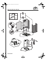
Minimalna odległość od palników: 50 cm (od palników elektrycznych), 75 cm (od palników
gazowych, olejowych lub węglowych). Podczas montażu należy przestrzegać kolejności
numeracji (1
Ö
2
Ö
3
Ö
.....) oraz odpowiednich instrukcji. Nie należy podłączać urządzenia do
zasilania zanim nie zakończy się całkowicie jego montażu.
Uwaga! Rura odprowadzająca dym i parę oraz kolanka nie są dostarczane i należy je
zakupić oddzielnie.
POPIS INSTALACE
Minimální vzdálenost od sporáků: 50 cm (elektrické sporáky), 75 cm (sporáky na plyn, naftu
nebo uhlí). Při montáži sledujte číslování (1
Ö
2
Ö
3
Ö
.....) a příslušné pokyny. Spotřebič
připojte k elektrické síti až po úplném dokončení instalace.
Upozornění! Nasávací trubka a pásky k upevnění nejsou součástí vybavení, musíte je
zakoupit.
INŠTALAČNÁ SCHÉMA
Minimálna vzdialenost' od sporáka: 50 cm (elektrické sporáky), 75 cm (plynové sporáky,
sporáky na naftu alebo uhlie). Pri montáži postupujte podľa číslic (1
Ö
2
Ö
3
Ö
.....) a dodržujte
príslušné pokyny. Spotrebič nezapájajte do siete, kým nie je inštalácia úplne ukončená.
Upozornenie! Rúra na odvádzanie dymov a upevňovacie svorky sa nedodávajú, musíte ich
kúpit' samostatne.
ÜZEMBE HELYEZÉSI ÚTMUTATÓ
A tűzhelytől való minimális távolság: 50 cm (elektromos tűzhely), 75 cm (gáz-, olaj- vagy
széntüzelésű tűzhely). A felszereléshez kövesse a számozást (1
Ö
2
Ö
3
Ö
.....) és a vonatkozó
utasításokat. Ne helyezze feszültség alá a készüléket addig, amíg nem történt meg
maradéktalanul az üzembe helyezés.
Figyelem! Az elvezető cső és a rögzítőpántok nem tartozékok, így azokat külön meg kell
vásárolni.
PL
CZ
SK
H
61833026.fm Page 1 Thursday, June 24, 2004 6:28 PM

5019 618 33026
HOO S00 - HOO S10 - HOO S40
СХЕМА УСТАНОВКИ
Минимальное расстояние до конфорок: 50 см (электрические конфорки), 75 см
(газовые, керосиновые или угольные горелки). Последовательность действий
при монтаже должна соответствовать нумерации (1
Ö
2
Ö
3
Ö
.....) и приведенным
инструкциям. Не подключайте прибор к сети до тех пор, пока установка не будет
полностью закончена.
Внимание! Выпускная труба и крепежные зажимы не входят в комплект поставки
и приобретаются отдельно.
КАРТА ЗА ИНСТАЛИРАНЕ
Минимално разстояние от печки: 50 см (електрически печки), 75 см (печки с газ,
нафта или въглища). За монтаж следвайте номерацията (1
Ö
2
Ö
3
Ö
.....) и
съответните инструкции. Не включвайте уреда към мрежата, докато
инсталирането не е завършено докрай.
Внимание! Тръбата за отвеждане не е предоставена и трябва да се закупи
отделно.
FIȘA DE INSTALARE
Distanţa minimă de la arzătoare: 50 cm (arzătoare electrice), 75 cm (arzătoare pe bază de
gaze, motorină sau cărbune). Pentru montare urmaţi numerotarea (1
Ö
2
Ö
3
Ö
.....) și
instrucţiunile corespunzătoare. Nu branșaţi aparatul la curent până când nu terminaţi
definitiv operaţia de instalare.
Atenţie! Tubul de evacuare și manșoanele de fixare nu fac parte din dotare și trebuie să fie
cumpărate separat.
INSTALLATION SHEET
Minimum height above cooker: 50 cm (electric cookers), 75 cm (gas, gas oil or coal
cookers). To assemble follow the numbers (1
Ö
2
Ö
3
Ö
.....) and relative instructions. Do
not connect the appliance to the electrical power supply until installation is
completed.
Warning! The exhaust pipe and clamps are not supplied and must be bought
separately.
RUS
BG
RO
GB
61833026.fm Page 2 Thursday, June 24, 2004 6:28 PM

5019 618 33026
HOO S00 - HOO S10 - HOO S40
61833026.fm Page 3 Thursday, June 24, 2004 6:28 PM

5019 618 33026
HOO S00 - HOO S10 - HOO S40
61833026.fm Page 4 Thursday, June 24, 2004 6:28 PM

5019 618 33026
HOO S00 - HOO S10 - HOO S40
61833026.fm Page 5 Thursday, June 24, 2004 6:28 PM

5019 618 33026
HOO S00 - HOO S10 - HOO S40
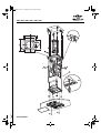
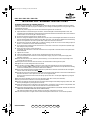
Preliminary information for installing the hood:
Expansion plugs are provided to secure the hood to most types of ceilings. A qualified technician is needed,
however, to make sure that the plugs are suitable for your ceiling. The ceiling must be strong enough to take
the weight of the hood.
Disconnect the power supply at the home main switch during electrical connections.
1. Adjust extension of the hood support structure, as the final height of the hood depends on this, and
remember that with installation completed the hood must be at least 50 cm above the hob in case of electric
cookers and 75 cm in case of gas or mixed cookers.
2. Fix the two sections of the structure using 8 screws.
3. Place the ceiling hole diagram directly above the hob (the centre of the diagram must match the centre of
the hob and the edges must be parallel to the sides of the hob - the side of the diagram with the wording
FRONT corresponds to the control panel side). Prepare the electrical connection.
4. Drill as shown (6 holes for 6 wall plugs - 4 plugs for hooking), screw the 4 outer screws leaving a space of
about 1 cm between the screw head and the ceiling.
5. Fit an exhaust pipe inside the truss and connect it to the collar of the motor compartment (exhaust pipe
and clamps are not provided).
6. Hook the truss to the 4 screws (see step 4).
CAUTION! The side of the truss with connection box corresponds to the side of the control panel with
hood assembled.
7. Tighten the 4 screws.
8. Insert and tighten another 2 screws in the remaining free holes for secure fixing.
9. Carry out the electrical connection to the mains power supply, only turn on the power supply with
assembly completed.
10. Hook the hood to the truss, check for perfect hooking - to hook the hood to the truss partially screw
4 screws (also see step 12).
11. Fixing the hood to the truss with two screws, will also facilitate centering the two parts.
12. Tighten the 4 screws fixing the truss to the hood.
13. For extractor operation (13A), connect the other end of the exhaust pipe to the home drain device.
For filter operation (13F), fit deflector F on the truss and fix it with 4 screws to the special bracket. Finally,
connect the exhaust pipe to the collar located on the deflector.
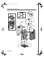
14. Fit the nuts with fixing hooks supplied inside
the top and bottom sections of the flues at the rectangular
slots. A total of 14 nuts must be fitted.
15. Join the two top sections of the flue to cover the truss so that one of the slots on the sections is situated on
the same side of the control panel and the other on the opposite side.
Screw the two sections with 8 screws and spring clips (4 each side - see the plan diagram for joining the
two sections).
16. Fix the top flue assembly to the truss, near the ceiling, with two screws (one each side).
17. Carry out electrical connection of control panel and bulbs.
18. Join the two bottom sections of the flue covering the truss using 6 screws and spring clips (3 each side - also
see the plan diagram for joining the two sections).
19. Insert the bottom section of the flue in the special seat to completely cover the motor compartment and
electrical connection box, and fix the hood with two screws from the inside.
20. Apply the 2 tabs (supplied) to cover the fixing points of the bottom flue (CAUTION! THE BOTTOM FLUE
TABS ARE THE NARROWER AND SHALLOWER ONES).
The wider and deeper tabs are those used for the top flue, and must be cut to size.
21. Turn the mains power on again at the central electrical panel and check for correct hood operation.
INSTALLATION - ASSEMBLY INSTRUCTIONS
ROSK H RUS BGCZPL GB
61833026.fm Page 21 Thursday, June 24, 2004 6:28 PM

5019 618 33026
HOO S00 - HOO S10 - HOO S40
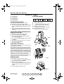
1. Control panel.
2. Grease filter.
3. Halogen bulbs.
4. Steam deflector.
5. Telescopic flue.
To clean the grease filter
Wash the grease filter at least once a month.
1. Disconnect the electrical power supply.
2. Remove the grease filters - Fig. 2: pull the spring
release handle (f) downwards, then remove the
filter.
3. After cleaning the grease filter refit in reverse
order, making sure the entire extraction surface is
covered.
Carbon filter Fitting and Maintenance
Fitting the carbon filter:
1. Disconnect the electrical power supply.
2. Remove the grease filter (f - Fig. 2).
3. Turn the side knobs 90° and then remove the
filter holder (g - Fig. 3).
4. Fit the carbon filter (h - Fig. 3) in the filter holder
(i - Fig. 3).
5. Refit the filter holder and secure it to the hood
with the screw (g - Fig. 3).
6. Refit the grease filter.
Carbon filter maintenance:
Unlike traditional carbon filters, this carbon filter can
be washed and reactivated.
With normal hood use, the filter should be cleaned
once a month. The best way to clean the filter is in a
dishwasher at the highest temperature possible, using
a normal dishwasher detergent. To avoid particles of
food or dirt settling on the filter during washing and
giving rise to unpleasant smells, it is advisable to wash
the filter on its own. After washing, dry the filter in the
oven at 100° C for 10 minutes to reactivate it.
The filter will retain its odour-absorbing capacity for
three years, after which it must be replaced.
Replacing bulbs
1. Disconnect the electrical power supply.
2. Use a small screwdriver or any other suitable tool
to prise off the lamp cover (Fig. 4).
3. Remove the burnt-out bulb.
Replace it with a PHILIPS STANDARD LINE bulb,
code 425409 12 V 20 W 30° GU4 Ø 35mm, or
similar.
4. Close the lighting unit (snap-close).
CONTROL PANEL
A. Light ON/OFF switch.
B. ON/OFF and speed 1 selector switch
(small amount of steam and fumes).
B+C.Speed 2 selector switch
(medium amount of steam and fumes).
B+D.Speed 3 selector switch
(large amount of steam and fumes).
Fig. 1
Fig. 2
Fig. 3
Fig. 4
PRODUCT SHEET
ROSK H RUS BGCZPL GB
61833026.fm Page 22 Thursday, June 24, 2004 6:28 PM
-
 1
1
-
 2
2
-
 3
3
-
 4
4
-
 5
5
-
 6
6
-
 7
7


IKEA HOO S00 S Program Chart
- Categorie
- Hote pentru aragaz
- Tip
- Program Chart
în alte limbi
- English: IKEA HOO S00 S
- slovenčina: IKEA HOO S00 S
- polski: IKEA HOO S00 S