Whirlpool AKR 951 IX Manualul utilizatorului
- Categorie
- Hote pentru aragaz
- Tip
- Manualul utilizatorului

5019 318 33279
KARTA INSTALACYJNA
Minimalna odległość pomiędzy powierzchnią kuchenki, na której ustawiane są naczynia, a najniższą
częścią okapu NIE POWINNA BYĆ mniejsza niż 50 cm w przypadku kuchni elektrycznej oraz 65 cm w
przypadku kuchni gazowej lub mieszanej. Przed instalacją sprawdzić też odległości podane w instrukcji
płyty kuchennej.
Okap powinien zainstalować wykwalifikowany specjalista. Podczas montażu należy przestrzegać
kolejności numeracji (1Ö2Ö3Ö.....).
Nie podłączać urządzenia do sieci zasilającej dopóki instalacja nie jest całkowicie zakończona.
OSTRZEŻENIE: Należy sprawdzić, czy w zestawie dostarczono rurę wylotową i zaciski. Jeśli nie,
należy je zakupić oddzielnie.
Uwaga: Części oznaczone symbolem “(*)” stanowią akcesoria opcjonalne, dostarczane tylko z
niektórymi modelami, bądź części nie dostarczane, które należy zakupić oddzielnie.
OSTRZEŻENIE: Urządzenie jest ciężkie. Przenoszenie i instalacja okapu powinny być
wykonywane przez co najmniej dwie osoby.
POPIS INSTALACE
Minimální vzdálenost mezi plotýnkami nádob na sporáku a nejnižší částí kuchyňského odsavače
NESMÍ být menší než 50 cm u elektrických sporáků a 65 cm u sporáků na plyn nebo kombinovaných
sporáků. Před začátkem instalace zkontrolujte vzdálenosti uvedené v návodu k varné desce.
Instalace musí provést odborný technik. Při montáži sledujte číslování (1 Ö2 Ö3 Ö.....).
Spotřebič připojte k elektrické síti až po úplném dokončení instalace.
UPOZORNĚNÍ: Ověřte si, zda je odtahová trubka a připevňovací pásky součástí dodávky. Není-li
tomu tak, je nutné je zakoupit samostatně.
Poznámka: Díly označené symbolem “(*)” jsou volitelným příslušenstvím, které se dodává pouze k
některým modelům, nebo se vůbec nedodává, a je nutné je zakoupit.
UPOZORNĚNÍ: Vzhledem k tomu, že je odsavač par velmi těžký, musí jeho stěhování a instalaci
provádět nejméně dvě osoby.
INŠTALAČNÁ SCHÉMA
Minimálna vzdialenost’ medzi plochou varnej dosky a najnižšej časti odsávača pár NESMIE BY menšia
ako 50 cm v prípade elektrickej varnej dosky a 65 cm v prípade plynovej alebo kombinovanej varnej
dosky. Pred ištaláciou si okrem toho overte vzdialenosti uvedené v návode na používanie varnej dosky.
Odsávač pár smie nainštalovat’ výhradne špecializovaný technik. Pri montáži postupujte podľa číslic
(1Ö2Ö3Ö.....).
Spotrebič nezapájajte k elektrickej sieti, kým nie je úplne ukončená jeho inštalácia.
UPOZORNENIE: Skontrolujte, či výbava odsávača obsahuje odvodnú rúru a upevňovacie svorky.
V opačnom prípade ich musíte kúpit’.
Upozornenie: Diely označené symbolom “(*)” predstavujú doplnkové príslušenstvo, ktoré sa dodáva iba
pri niektorých modeloch alebo sú to časti, ktoré treba zakúpit’.
UPOZORNENIE: Výrobok má nadmernú hmotnost’, preto je nevyhnutné, aby ho prenášali a
inštalovali aspoň dve alebo viac osôb.
ÜZEMBE HELYEZÉSI ÚTMUTATÓ
A konyhai elszívó legalacsonyabb része és a főzőberendezésen kialakított edényfelület közötti
távolságnak elektromos tűzhely esetén legalább 50 cm, gáz- vagy vegyes tűzhely esetén pedig
legalább 65 cm NAGYSÁGÚNAK KELL LENNIE. Az üzembe helyezés előtt ellenőrizze a főzőlap
használati útmutatójában feltüntetett távolságokat is.
A szagelszívó beépítését szakembernek kell végeznie. A felszereléshez kövesse a számozást
(1Ö2Ö3Ö.....).
A készüléket csak akkor szabad áram alá helyezni, ha az üzembe helyezés már befejeződött.
FIGYELMEZTETÉS: Ellenőrizze, hogy az elvezető cső és a rögzítőpántok a készülék
tartozékai-e. Ellenkező esetben ezeket külön kell megvásárolni.
Megjegyzés: A “(*)” jelzésű alkatrészek olyan opcionális tartozékok, amelyek csak néhány modellhez
járnak, illetve amelyeket külön meg kell vásárolni.
FIGYELMEZTETÉS: Nagy súlya miatt a készülék mozgatását és üzembe helyezését legalább két
vagy több személynek kell végeznie.
PL
CZ
SK
H

5019 318 33279
ИНСТРУКЦИЯ ПО УСТАНОВКЕ
Минимальное расстояние между опорной поверхностью для посуды на плите и самой нижней
частью вытяжки ДОЛЖНО БЫТЬ не менее 50 cm при наличии электрической плиты и не менее
65 cm при наличии газовых или комбинированных плит. Прежде чем приступать к установке,
проверьте также расстояние, указанное в руководстве по плите.
Установка вытяжки должно выполняться квалифицированным специалистом.
Последовательность действий при монтаже должна соответствовать нумерации (1Ö2Ö3Ö.....).
Не подключайте вытяжку к сети электропитания до окончательного завершения монтажа.
ПРЕДУПРЕЖДЕНИЕ: Проверьте, входят ли в комплект поставки выпускная труба и
крепежные зажимы. В противном случае необходимо приобрести их отдельно.
Примечание: детали, отмеченные символом “(*)”, представляют собой дополнительные
принадлежности, поставляемые только в некоторых моделях или не включаемые в комплект
поставки. В последнем случае эти детали приобретаются отдельно.
ПРЕДУПРЕЖДЕНИЕ: Устройство отличается большим весом; для его переноски и
установки требуется участие не менее двух человек.
КАРТА ЗА ИНСТАЛИРАНЕ
Минималното разстояние между повърхността, на която се поставят съдовете върху уреда за
готвене, и най<ниската част на аспиратора на кухнята НЕ ТРЯБВА ДА БЪДЕ по<малко от 50 cm
за електрическите печки и 65 cm за печки на газ или комбинирани. Преди инсталацията, обаче,
проверете разстоянията посочени в ръководството на плочата за готвене.
Инсталирането на аспиратора трябва да се извърши от техник специалист. При монтажа,
следвайте номерацията (1Ö2Ö3Ö.....).
Не свързвайте уреда към електрическата мрежа, докато инсталирането не е завършено
напълно.
ВНИМАНИЕ: Проверете дали тръбата за отвеждане и скобите за фиксиране са
приложени в комплекта. В противен случай те трябва да се закупят.
Забележка: Частите, означени със символа “(*)”, са допълнителни принадлежности, които
са включени само към някои модели, или части, които се закупуват допълнително.
ВНИМАНИЕ: Уред с много голямо тегло < преместването и инсталирането на аспиратора
трябва да се извършва от най<малко двама души.
FIȘA DE INSTALARE
Distanţa minimă între suprafaţa de sprijin a recipientelor de pe mașina de gătit și partea cea mai joasă
a hotei de bucătărie NU TREBUIE SĂ FIE mai mică de 50 cm în cazul plitelor electrice și de 65 cm în
cazul plitelor cu gaz sau mixte. Înainte de instalare verificaţi și distanţele indicate în manualul mașinii
de gătit.
Instalarea hotei trebuie să fie efectuată de un tehnician specializat. Pentru montaj urmaţi numerotarea
(1Ö2Ö3Ö.....).
Nu conectaţi aparatul la reţeaua electrică până când nu terminaţi definitiv operaţia de instalare.
ATENŢIE: Verificaţi dacă tubul de evacuare și manșoanele de fixare sunt furnizate în dotare. În
caz contrar, trebuie cumpărate separat.
Notă: Elementele marcate cu simbolul “(*)” sunt accesorii opţionale furnizate doar la unele modele sau
sunt elemente care nu sunt furnizate, ci trebuie cumpărate.
ATENŢIE: Produs cu greutate mare, deplasarea și instalarea hotei trebuie efectuate de cel puţin
două sau mai multe persoane.
INSTALLATION AND USE
The distance between the pot/pan support surface on the cooking appliance and the lowest part of the hood
MUST NOT BE less than 50 cm for electric cookers and 65 cm for gas or combination cookers. Before
installation, also check the distances specified in the hob manual.
Hood installation must be carried out by a specialised technician. For installation, follow the steps (1Ö2Ö3Ö.....).
Do not connect the appliance to the power supply until installation has been completed.
WARNING: Check whether the exhaust pipe and clamps are supplied. If not, they must be purchased
separately.
Note: Parts marked with the symbol “(*)” are optional accessories supplied only with some models or parts not
supplied, to be purchased separately.
WARNING: Very heavy product; hood handling and installation must be carried out by at least two persons.
RUS
BG
RO
GB

5019 318 33279
?

5019 318 33279
.
Rys. 1
Obr. 1
Obr. 1
1. ábra
Рис. 1
Фиг. 1
Fig. 1
Fig. 1

5019 318 33279
Rys. 2
Obr. 2
Obr. 2
2. ábra
Рис. 2
Фиг. 2
Fig. 2
Fig. 2

5019 318 33279
Rys. 3
Obr. 3
Obr. 3
3. ábra
Рис. 3
Фиг. 3
Fig. 3
Fig. 3

5019 318 33279
SAFEGUARDING THE ENVIRONMENT
1. Packing
Packing materials are 100% recyclable and are marked with the
recycling symbol .Comply with the local regulations for
disposal. The packing materials (plastic bags, polystyrene, etc.)
are a potential source of danger and must be kept out of the
reach of children.
2. Product
This appliance is marked in compliance with European Directive
2002/96/EC, Waste Electrical and Electronic Equipment (WEEE).
By ensuring that this appliance is correctly scrapped, the user can
help prevent potentially harmful consequences for the
environment and the health of people.
The symbol on the product or the accompanying
documentation indicates that this product should not be treated
as domestic waste but must be taken to a suitable collection
centre for the recycling of electrical and electronic equipment.
Disposal must be carried out in compliance with local regulations
on waste disposal.
For further information on the treatment, recovery and recycling
of this product, contact the competent local office, the
household waste collection service or the shop where you
purchased the appliance.
IMPORTANT INSTRUCTIONS FOR
SAFETY
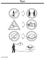
WARNING: To reduce the risk of accidents, electric shock,
injury or damage, when using the hood comply with the basic
precautions, including the following.
1. Always disconnect the hood from the power supply before
carrying out any installation or maintenance operation on the
appliance.
2. Installation must be carried out by a specialised technician, in
compliance with the manufacturer’s instructions and local
safety regulations.
3. Earthing of the appliance is compulsory. (Not possible for
Class II hoods).
4. Never use multisockets and extension leads.
5. The electrical components must no longer be accessible to
the user after installation.
6. Do not touch the hood with wet parts of the body or use it
when barefoot.
7. Do not pull the appliance power cable to unplug it.
8. After-sales service – do not repair or replace any part of the
hood unless specifically indicated in the manual. All other
maintenance services must be carried out by a specialised
technician.
9. When drilling the wall, make sure not to damage the
electrical connections and/or pipes.
10. The ventilation ducts must always discharge to the outside.
11. The Manufacturer declines any liability for improper use or
incorrect setting of the controls.
12. The appliance is not intended for use by children or persons
with limited physical, sensory or mental abilities or without
experience and knowledge of it, unless they are under the
supervision of or instructed in its use by a person responsible
for their safety.
13. Keep children away.
14. To reduce the risk of fire, only use a metal inlet duct.
15. Children must be supervised so that they do not play with
the appliance.
16. The product must be disposed of in compliance with local
regulations on waste disposal.
17. For further information on the treatment, recovery and
recycling of this product, contact the competent local office,
the household waste collection service or the shop where
you purchased the appliance.
18. Regular cleaning and maintenance is essential for correct
hood operation and good performance. Frequently clean all
encrustations from dirty surfaces to prevent the
accumulation of grease. Regularly clean or replace filters.
19. Do not “flambé” food under the hood. Naked flames could
cause a fire.
20. The room must have adequate ventilation when the hood is
used at the same time as appliances operating on gas or
other fuels.
21. The discharge air must not be eliminated in a duct used to
remove fumes produced by appliances operating on gas or
other fuels, but must have a separate outlet. All the national
regulations on air discharge envisaged by art. 7.12.1 of CEI
EN 60335-2-31 must be observed.
22. If the hood is used together with other appliances operating
on gas or other fuels, the negative pressure in the room
must not exceed 4 Pa (4 x 10
-5
bar). Therefore, make sure
the room is adequately ventilated.
23. Do not leave pans unattended when frying, since the cooking
oil could catch fire.
24. Make sure the lamps are cold before touching them.
25. The hood is not a shelf, therefore do not overload or place
objects on it.
26. Do not use or leave the hood without its lamps correctly
installed - risk of electric shock.
27. Wear work gloves for all installation and maintenance
operations.
28. The product is not suitable for outdoor use.
29. The air sucked by the hood must not be eliminated through
the same flue of the heating system or other appliances using
gas or other fuels.
GBSKCZPL H
RUS
BG
RO

5019 318 33279
Electrical connection
The mains voltage must match that given on the rating plate
located inside the hood. If provided with a plug, connect the
hood to a socket complying with the current regulations and
located in an accessible area. If it does not have a plug (direct
connection to the power supply) or if the plug is not in an
accessible place, fit a suitable double-pole switch that ensures
complete disconnection from the power supply in category III
overvoltage conditions, complying with the installation rules.
WARNING: Before reconnecting the hood circuit to the
power supply and checking correct operation, always make sure
the power cable is correctly fitted and that it was NOT crushed
in its housing during installation. Make sure to have this operation
carried out by a specialised technician.
Cleaning the hood
WARNING! Failure to remove oil/grease (at least once a
month) could result in fire.
Use a soft cloth with a neutral detergent. Never use abrasive
substances or alcohol.
Before using the hood
Please read these instructions carefully and keep them for future
reference, in order to ensure best use of your hood.
The packing materials (plastic bags, polystyrene, etc.) are a
potential source of danger and must be kept out of the reach of
children.
Make sure the hood has not been damaged during transport.
Declaration of conformity
This product has been designed, manufactured and put on the
market in conformity with:
- safety objectives of the “Low Voltage” Directive 2006/95/EC
(which replaces 73/23/EEC as amended)
- protection requirements of “EMC” Directive 89/336/EEC
amended by Directive 93/68/EEC.
Troubleshooting guide
If the hood does not work:
• Is the plug properly inserted in the power socket?
• Is there a power failure?
If the hood is not extracting enough:
• Is the right speed selected?
• Do the filters need cleaning or replacing?
• Are the air outlets blocked?
If the lamp does not work:
• Does the lamp need replacing?
• Is the lamp correctly fitted?
AFTER-SALES SERVICE
Before calling the After-Sales Service
1. Check to see if you can fix the problem yourself (see
“Troubleshooting Guide”).
2. Switch the appliance off and then on again to check if the
problem has been eliminated.
3. If the problem persists, contact the After-Sales Service.
Specify:
• the type of fault,
• the product model given on the dataplate inside the hood,
visible on removing the grease filters,
• your full address,
• your telephone number and area code,
• the Service code (the number under the word SERVICE on
the dataplate inside the hood, behind the grease filter).
If any repairs are necessary, contact an authorised Service Centre
(to ensure the use of original spare parts and correct repair).
Failure to comply with these instructions can compromise the
safety and quality of the product.
GBSKCZPL H
RUS
BG
RO

5019 318 33279
INSTALLATION - ASSEMBLY INSTRUCTIONS
Expansion plugs are provided to secure the hood to most types of ceilings. However, a qualified technician is needed to check the
suitability of the materials according to the type of wall/ceiling. The wall/ceiling must be strong enough to take the weight of the hood.
When making the electrical connection, disconnect the power supply at the main switch in the home.
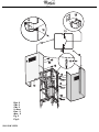
Fig. 1
1. Adjust the extension of the hood support structure, as the final height of the hood depends on this.
Note: In some cases the top section of the truss is fixed to the bottom section with 1 or more screws; if necessary, check and
temporarily remove them to enable adjustment of the support structure.
2. Fix the two sections of the structure using 16 screws (4 each corner).
For extensions exceeding the minimum, fit 1 or 2 brackets (depending on the number supplied) on the top section to reinforce it.
Note: 1 bracket may already be temporarily fixed to the truss with 2 screws for transport purposes; if necessary, move it to the
required position or complete fixing with 6 more screws.
To fit the brackets, proceed as follows:
a. Open the brackets slightly in order to fix them to the outside of the structure.
b. Position the reinforcement bracket directly above the point where the two sections of the hood are joined and secure with 8
screws (2 each corner).
If supplied, fix the second reinforcement bracket so that it is equidistant from the first reinforcement bracket and the top edge of
the truss, secure with 8 screws (2 each corner).
Note: When positioning and fixing the reinforcement bracket/s, make sure they do not hinder fixing of the exhaust pipe (extractor
version) or the deflector (filter version).
3. Hook the hood to the truss, check for perfect hooking - to hook the hood to the truss tighten the 16 screws (4 each corner).
4. Place the ceiling drilling diagram directly above the hob (the centre of the diagram must match the centre of the hob and the edges
must be parallel to the sides of the hob - the side of the diagram with the wording FRONT corresponds to the control panel side).
Prepare the electrical connection.
5. Drill as shown (6 holes for 6 wall plugs - 4 plugs for hooking), screw the 4 screws in the outer holes, leaving a space of about 1 cm
between the screw head and the ceiling.
6. Hook the truss to the 4 screws on the ceiling (see step 4).
7. Tighten the 4 screws.
8. Insert and tighten another 2 screws in the remaining free holes for secure fixing.
9. Fit an exhaust pipe inside the truss and connect it to the collar of the motor compartment (exhaust pipe and clamps are not
provided). The exhaust pipe must be long enough to reach the outside (Extractor version) or the deflector F (Filter version).
10. For filter version only: fit the deflector F on the truss and fix it to the appropriate bracket with 4 screws, then connect the exhaust
pipe to the collar on the deflector.
11. Carry out the electrical connection to the house power supply; switch the power on only when assembly is completed.
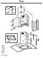
Fig. 2
12. Fit the nuts provided with fixing hooks inside the top and bottom sections of the flues at the rectangular slots; total of 14 nuts must
be fitted.
13. Join the two top sections of the flue to cover the truss so that one of the slots on the sections is on the same side as the control
panel and the other is on the opposite side.
Screw the two sections with 8 screws (4 each side - see the plan diagram for joining the two sections).
14. Fix the upper flue assembly to the truss, near the ceiling, with two screws (one each side).
Fig. 3
15. Join the two bottom sections of the flue covering the truss, using 6 screws (3 each side - also see the plan diagram for joining the
two sections).
16. Insert the bottom section of the flue in the special seat so that it completely covers the motor compartment and electrical
connection box, then secure it from inside the hood using two screws.
17. Apply the 2 tabs (supplied) to cover the fixing points of the bottom flue sections (IMPORTANT! THE TABS FOR THE BOTTOM
FLUE ARE THE NARROWER AND LESS DEEP ONES).
The wider and deeper tabs are those used for the top flue, and must be cut to size.
18. Turn the power on again at the main electrical panel and check correct hood operation.
GBSKCZPL H
RUS
BG
RO

5019 318 33279
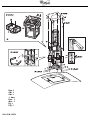
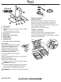
1. Control panel
a. Light switch
b. Extraction and minimum extraction power ON/OFF
button.
c. Medium extraction power button.
d. Maximum extraction power button.
2. Grease filter
3. Grease filter release handle
4. Halogen lamp
5. Steam deflector
6. Telescopic flue
7. Air outlet (for filter version only)
Grease filters:
Ther metal grease filter has an unlimited
life and must be washed once a month
by hand or in a dishwasher at low
temperature and with a short cycle.
Cleaning in a dishwasher may cause
discolouring of the grease filter, but its
filtering efficiency is unaffected.
a. press the handle to remove the filter
b. remove it.
After cleaning the filter and leaving it to dry, proceed in
reverse order to refit it.
Replacing the halogen lamps:
1. Disconnect the hood from the house power supply.
WARNING: Wear gloves.
2. Use a small screwdriver to gently prise (at the three
points indicated in the figure) the lamp cover off.
3. Remove the burnt-out lamp and fit a new one.
WARNING: Use 20 W MAX - G4 halogen lamps only.
Close the lighting unit (snap-on).
Activated carbon filter
(filter hoods only):
The carbon filter must be cleaned once a month in a
dishwasher at the highest temperature, using a normal
dishwasher detergent. Wash the filters on their own.
After washing, reactivate the carbon filter by drying it in the
oven at 100°C for 10 minutes.
Change the carbon filter every 3 years.
Fitting the carbon filter:
1. Remove the grease filter.
2. Remove the filter holder by turning the knobs 90°.
3. Fit the carbon filter “i” in the filter holder “h”.
Carry out the above procedure in reverse order to refit the
filter holder and grease filter.
a
b
GBSKCZPL H
RUS
BG
RO
-
 1
1
-
 2
2
-
 3
3
-
 4
4
-
 5
5
-
 6
6
-
 7
7
-
 8
8
-
 9
9
-
 10
10


Whirlpool AKR 951 IX Manualul utilizatorului
- Categorie
- Hote pentru aragaz
- Tip
- Manualul utilizatorului
în alte limbi
- English: Whirlpool AKR 951 IX User guide
- slovenčina: Whirlpool AKR 951 IX Užívateľská príručka
Lucrări înrudite
-
Whirlpool AKR 767 IX Manualul utilizatorului
-
Whirlpool AKR 759 IX Manualul utilizatorului
-
-
Whirlpool AKR 970 NB Program Chart
-
IKEA HOO D00S Manualul utilizatorului
-
-
Whirlpool AKR 995 IX Program Chart
-
-
Whirlpool AKR 950 IX WP Program Chart
-
Whirlpool AKR 951/1 IX Manualul utilizatorului