Thermo Fisher Scientific ThermoChill Series, ThermoChill LR Series Recirculating Chillers Manual de utilizare
- Tip
- Manual de utilizare

Thermo Scientific
ThermoChill Series
ThermoChill LR Series
Recirculating Chillers
Thermo Scientific Manual P/N U01083 Rev. 10/29/2019
Multilingual Quick
Start Guides
Multilingual Essential
Safety Instructions
Installation
Operation
Basic Maintenance
Visit our Web site at:
http://www.thermofisher.com/tc
Product Service Information, Applications
Notes, SDS Forms, e-mail.
Voice Info: (800) 258-0830


Thermo Scientific
ThermoChill Series
ThermoChill LR Series
Label
Recirculating Chillers
Thermo Scientific Manual P/N U01083 Rev. 10/29/2019
Multilingual Quick
Start Guides
Multilingual Essential
Safety Instructions
Installation
Operation
Basic Maintenance
Visit our Web site at:
http://www.thermofisher.com/tc
Product Service Information, Applications
Notes, SDS Forms, e-mail.
Voice Info: (800) 258-0830

Thermo Fisher Scientic
25 Nimble Hill Road
Newington, NH 03801
Tel : (800) 258-0830 or
(603) 436-9444
Fax : (603) 436-8411
www.thermoscientic.com/tc
Sales, Service, and Customer Support
25 Nimble Hill Road
Newington, NH 03801
Tel: (800) 258-0830
Sales: 8:00 am to 5:00 pm
Service and Support: 8:00 am to 6:00 pm Monday
through Friday (Eastern Time)
Fax: (603) 436-8411
service.tc.us@thermosher.com
Dieselstrasse 4
D-76227 Karlsruhe, Germany
Tel : +49 (0) 721 4094 444
Fax : +49 (0) 721 4094 300
info.tc.de@thermosher.com
Building 6, No. 27
Xin Jinqiao Rd., Shanghai 201206
Tel : +86(21) 68654588
Fax : +86(21) 64457830
info.china@thermosher.com
Statement of Copyright
Copyright © 2019 Thermo Fisher Scientic. All rights reserved.
This manual is copyrighted by Thermo Fisher Scientic.
Users are forbidden to reproduce, republish, redistribute, or resell any materials from this manual in either machine-readable form or any
other form.

ThermoChill
Thermo Scientific
Contents
Quick Start Guides
Preface .................................................................................................................................i
Compliance ..............................................................................................................i
WEEE .....................................................................................................................i
After-Sale Support .................................................................................................ii
Unpacking ...............................................................................................................ii
Warranty ..................................................................................................................ii
Feedback ..................................................................................................................ii
Section 1 Safety ..................................................................................1-1
Warnings ..............................................................................................................1-1
Section 2 General Information .............................................................2-1
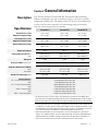
Description .........................................................................................................2-1
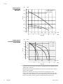
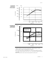
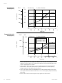
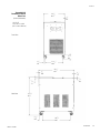
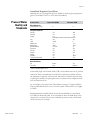
Specications ...................................................................................................... 2-1
Wetted Materials .................................................................................................2-9
Section 3 Installation ...........................................................................3-1
Site Requirements ..............................................................................................3-1
Electrical Requirements ....................................................................................3-2
Drain Valve Installation ....................................................................................3-3
Plumbing Requirements ....................................................................................3-4
Process Fluid Requirements ............................................................................. 3-5
Compatibility with Approved Fluids ..............................................................3-6
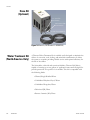
Process Water Quality and Standards .............................................................3-7
Filling ..................................................................................................................3-8
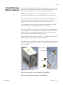
External Pressure Regulator (Optional) .........................................................3-9
Hose Kit (Optional) ........................................................................................3-10
Section 4 Operation .........................................................................................................4-1
Controller ............................................................................................................4-1
Start Up/Shut Down .........................................................................................4-2
Circuit Protector ................................................................................................4-2
Start Up ...............................................................................................................4-2
Setpoint................................................................................................................4-2
Temperature Alarm ...........................................................................................4-3
Serial Comm (Optional) ....................................................................................4-3
Setup/Tune Loop ..............................................................................................4-4
Stopping ..............................................................................................................4-6
Draining ...............................................................................................................4-6
Shipment/Storage ..............................................................................................4-6
Decommissioning/Disposal ............................................................................4-7

ThermoChill
Contents
Thermo Scientific
Section 5 Preventive Maintenance............................................................................... 5-1
Cleaning ............................................................................................................... 5-1
Condenser ...........................................................................................................5-1
Fluid Maintenance .............................................................................................5-1
Reservoir .............................................................................................................5-1
Pump Strainer .....................................................................................................5-2
Hoses ..................................................................................................................5-2
Temperature Sensor (rdt1) Calibration ...........................................................5-3
Section 6 Troubleshooting .....................................................................6-1
Error Codes ........................................................................................................6-1
Checklist ..............................................................................................................6-2
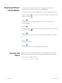
Displaying Software Version ............................................................................6-4
Controller PID Values.......................................................................................6-4
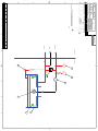
Flow Diagram
Appendix A Country Specic 230 VAC, 50 Hz, 1 Ø Requirements ...............................A-1
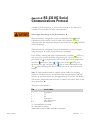
Appendix B Serial Communications .................................................................................... B-1
Declaration of Conformity
WARRANTY

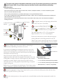
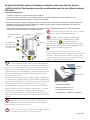
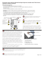
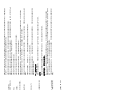
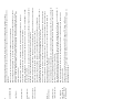
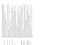
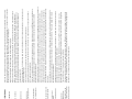
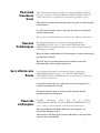
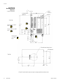
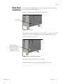
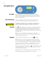
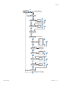
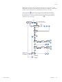
Process Outlet
1/2" FNPT Brass
J1 Serial Communications
(Optional)
Circuit Protector
Power Inlet
Process Inlet
1/2" FNPT Brass
DRAIN
1 If supplied, remove the drain plug and install the
drain valve to the rear of the chiller.
2 Connect the PROCESS OUTLET to the
uid inlet on your application. Connect the PROCESS
INLET to the uid outlet on your application.
The chiller ships with a 1/2” x 3/8’’ polyethylene
adapter and also a 1/2” x 1/2” nylon adapter.
Ensure all connections are secure and that the proper
sealant/lubricant for the tting material is used. (If
Teon® tape is used, ensure the tape does not overhang
the rst thread as it could shred and get into the uid.)
Safety Precautions:
The chiller is designed for indoor use only.
Never place the chiller in a location where excessive heat, moisture, inadequate ventilation, or corrosive materials are present.
Never use corrosive uids with this chiller.
Never connect process uid lines to your facility water supply or to any pressurized liquid source.
If your chiller is equipped with a positive displacement pump (PD1 or PD2), ensure your application plumbing lines and ttings are
rated to withstand a minimum of 115 psi.
Before using any uid, or performing maintenance where contact with the uid is likely, refer to the manufacturer’s MSDS for
handling precautions.
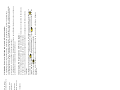
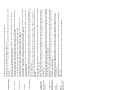
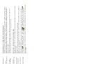
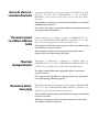
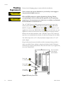
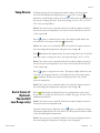
3 Prior to lling, ensure the reservoir drain or drain plug is
closed and that all plumbing connections are secure.
Loosen the two thumbscrews securing the reservoir cover to the
chiller. Ensure the uid lter is securely in place in the bottom of
the reservoir. Slowly ll the reservoir with clean process uid until the
uid reaches the reservoir's lip.
Since the reservoir capacity may be small compared to your
application and air may need to be purged from the lines, have extra
cooling uid on hand to keep the system topped off when external
circulation is started. Failure to keep the reservoir full to the lip
will result in loss of cooling capacity and possible icing of exposed
copper cooling coils.
Replace the cover and tighten the thumbscrews. The lid must remain
secure to minimize evaporation and keep debris out of the reservoir.
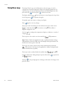
4 Verify the appropriate voltage. Insert female end of power cord into the chiller power inlet and then insert
male end of power cord into a power outlet.
5 Place the circuit protector to the up position, the controller ashes and the alarm momentarily sounds. See
next page.
1
2
4
5
Approved uids are:
• Filtered/Single Distilled water
•0 - 75% Laboratory Grade Ethylene Glycol/Water
•0 - 75% Laboratory Grade Propylene Glycol/Water
• Deionized water (1 - 3 MΩ-cm, compensated)
Thumbscrews
Reservoir Lip
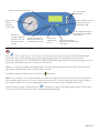
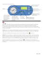
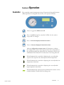
This quick start guide is intended for initial start up only. For all other procedures you must refer
to the manual. Also, if any of these steps are not clear read the manual before proceeding.

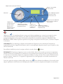
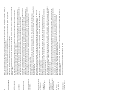
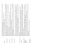
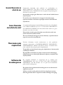
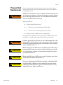
Press . The controller does a self-test (the controller quickly sequences through its LEDs and momentarily
sounds the alarm) and then displays the recirculating uid temperature. The refrigeration system and the
recirculation pump then start. The RECIRCULATING PRESSURE gauge displays the pump operating pressure. If
the pressure needs adjusting, refer to Section 3 in the manual.
Note If on start up the chiller’s recirculating uid is outside either temperature limit, the chiller operates but the
appropriate indicator ashes until the uid is within the limit.
To display/change the setpoint use the arrow keys, illuminates.
Note If the arrow keys are not pressed within 10 seconds the display returns to the current reservoir temperature.
The controller will not allow you to enter a setpoint closer than 2°C of either temperature alarm setting. Trying to
use a setpoint within 2°C causes the appropriate indicator to ash and sounds the audible alarm twice.
Once the desired setpoint is displayed, press to conrm the change. The display rapidly ashes the new value
for a short period and then returns to the recirculating uid temperature.
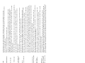
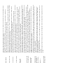
Use this key to
toggle the chiller
on or off.
Indicates refrigeration system status.
Indicates the
controller is displaying
the setpoint. Press the
arrow keys to change
the value.
Pressure Gauge
Indicates
pressure at
outlet of chiller.
Indicates the controller is
displaying the chiller’s low
temperature alarm setting.
Indicates the controller is
displaying the high temperature
alarm setting.
Optional. Indicates the chiller
is operating in the serial
communication mode.
Press to change the
displayed value.
Press to sequence through the
four indicators and accept the
displayed value.
6
Page 2 of 2

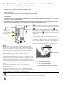
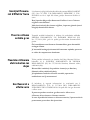
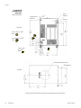
1 Bei Auslieferung, entfernen Sie die Ablassschraube und
installieren Sie das Ablassventil auf der Rückseite des Kühlers.
2Verbinden Sie den PROZESSAUSLASS mit
dem Flüssigkeitseinlass Ihrer Applikation. Verbinden Sie den
PROZESSEINLASS mit dem Flüssigkeitsauslass Ihrer
Applikation.
Alle Verbindungen müssen sicher hergestellt worden sein,
und für die Anschlüsse sind die entsprechend vorgeschriebe-
nen Dichtungs-/Schmiermittel zu verwenden. (Bei Verwen-
dung von Teon® Band ist darauf zu achten, dass das Band
nicht über das erste Gewinde übersteht, da es ansonsten
zerkleinert werden und in die Flüssigkeit gelangen kann.)
Zulässige Flüssigkeiten sind:
• Geltertes/einfachdestilliertesWasser
• 0–75%Ethylenglycol/Wasser
• 0–75%Propylenglycol/Wasser
• DeionisiertesWasser(1-3MΩ-cm,kompensiert)
Sicherheitsvorkehrungen:
DasGerätdarfnuringeschlossenenRäumenbetriebenwerden.
StellenSiedasGerätniemalsanOrtenauf,woesübermäßigerHitze,Feuchtigkeit,unzureichenderBelüftungoderkorrosiven
Stoffenausgesetztist.
VerwendenSieniemalsbrennbareoderkorrosiveFlüssigkeitenindiesemGerät.
SchließenSieniemalsProzessüssigkeitsleitungenandieKühlwasserversorgungoderaneinenAnschlussfürunterDruckstehende
Flüssigkeitenan.
FallsIhrGerätmiteinerVerdrängerpumpeausgestattetist,müssendieLeitungenundAnschlüsseIhrerApplikationeinemDruckvon
mindestens115psi/ca.9,8barstandhalten.
BeachtenSiedieimSicherheitsdatenblattdesHerstellersbeschriebenenVorsichtsmaßnahmen,bevorSieFlüssigkeiteneinsetzen
odereineWartungdurchführen,beidenenSiemöglicherweisemitFlüssigkeiteninBerührungkommen.
3 Stellen Sie vor dem Befüllen des Behälters sicher, dass das
Ablassventil oder die Ablassschraube auf der Rückseite des Kühlers
geschlossen ist und dass alle Wasseranschlüsse sicher verbunden sind.
Lösen Sie die beiden Flügelschrauben, mit denen der Behälterdeckel
am Gerät festgeschraubt ist. Das Flüssigkeitslter muss fest am
Behälterboden sitzen. Füllen Sie den Behälter langsam bis zur
Füllstandsmarkierung mit sauberer Prozessüssigkeit.
Da möglicherweise die Kapazität des Behälters im Vergleich zu Ihrer
Applikation eher gering ist und Luft aus den Leitungen gespült werden
muss, sollten Sie weitere Kühlüssigkeit zum Nachfüllen bereithalten,
wenn der externe Kreislauf gestartet wird. Wenn der Behälter nicht bis
zur Füllstandsmarkierung gefüllt ist, vermindert sich die Kühlleistung des
Geräts.
Setzen Sie den Behälterdeckel wieder auf und ziehen Sie die
Flügelschrauben fest.
Der Behälterdeckel muss stets fest sitzen, um Verdunstung und das
Eindringen von Verschmutzungen in den Behälter zu vermeiden und
mögliche Vereisung der freiliegenden Kupferkühlschlangen.
Flügelschrauben
Füllstandsmarkierung
Seite1von2
Prozessauslass
1/2" FNPT Messing
Serielle-Schnittstelle J1
(optional)
Netzschalter
Netzanschluss
Prozesseinlass
1/2" FNPT Messing
DRAIN
1
2
4
5
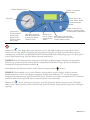
Diese Schnellstartanleitung ist nur für die erste Inbetriebnahme vorgesehen. Für alle anderen
Fragen müssen Sie die Bedienungsanleitung benutzen.
4 Kontrollieren Sie, dass die korrekte Spannung eingestellt ist. Stecken Sie den geräteseitigen Anschlussstecker des
Netzkabels in die Netzbuchse des Gerätes und den Netzstecker des Netzkabels in eine Steckdose.
5 Schalten Sie den Netzschalter in die obere Stellung. Der Regler blinkt, und der Alarm ertönt kurz. Siehe folgende Seite.

Drücken Sie . Der Regler führt einen Selbsttest aus (d. h. alle LEDs leuchten kurzzeitig und der Alarm
ertönt kurz) und zeigt dann die Temperatur der umgewälzten Flüssigkeit an. Dann beginnen Kühlsystem und
Umwälzpumpe zu arbeiten. Am MANOMETER wird der Betriebsdruck der Pumpe angezeigt. Lesen Sie Kapitel 3
in der Gebrauchsanweisung, wenn der Druck eingestellt werden muss.
HINWEIS Wenn die Temperatur der umgewälzten Flüssigkeit zu Betriebsbeginn außerhalb des eingestellten
Bereichs liegt, arbeitet das Gerät normal, aber die entsprechende LED blinkt solange, bis sich die Temperatur
innerhalb des festgelegten Bereiches bendet.
Durch Betätigen der Pfeiltasten können Sie den Sollwert anzeigen/ändern. leuchtet.
HINWEIS Wird innerhalb von 10 s keine Pfeiltaste mehr gedrückt, zeigt das Display wieder die aktuelle
Behältertemperatur an. Der in den Regler eingegebene Sollwert muss mindestens 2°C von den festgelegten
Temperatur-Alarmgrenzwerten (siehe nächste Seite) liegen. Wenn Sie einen Sollwert innerhalb dieses 2°C-Bereiches
einstellen, blinkt die jeweilige LED und der akustische Alarm ertönt zweimal.
Drücken Sie , um die Änderung zu bestätigen, wenn der gewünschte Sollwert angezeigt wird. Am Display
blinkt der neue Wert kurzzeitig schnell, und dann wird wieder die aktuelle Temperatur der umgewälzten Flüssigkeit
angezeigt.
Mit dieser Taste
kann das Gerät ein-
und ausgeschaltet
werden.
Zeigt den Kühlsystemstatus an
Weist darauf hin,
dass der Regler den
Sollwert anzeigt.
Drücken Sie die
Pfeiltasten, um den
Wert zu ändern.
Manometer
Weist darauf hin, dass der
Regler den Alarmgrenzwert
für die minimal mögliche
Temperatur anzeigt.
Weist darauf hin, dass der Regler
den Alarmgrenzwert für die maximal
mögliche Temperatur anzeigt.
Optional. Zeigt an, dass
sich das Gerät im seriellen
Kommunikationsmodus
befindet.
Drücken, um angezeigten
Wert zu ändern
Drücken, um durch die vier
Anzeigen zu navigieren und den
angezeigten Wert zu übernehmen.
6
Seite 2 von 2

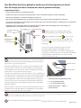
Sortie vers Application
laiton FNPT 12 mm
Communications série J1
(option)
Protection de
circuit
Prise
d'alimentation
Arrivée de process
laiton FNPT 12 mm
DRAIN
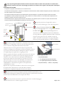
1 S’il est fourni, retirez le bouchon de vidange et installez
le robinet de vidange à l’arrière du refroidisseur.
2Raccorder sur le ThermoChill LA SORTIE DU
FLUIDE (OUTLET : DU THERMOCHILL VERS
L'APPLICATION) à l'entrée de l'application.
Raccorder sur le ThermoChill LE RETOUR DU FLUIDE
(INLET : DE L'APPLICATION VERS THERMOCHILL)
à la sortie de liquide de l'application.
S'assurer que tous les raccords sont bien serrés et que le
produit d'étanchéité/lubriant est adéquat pour le matériau du
raccord est utilisé. (Si du ruban en Teon® est utilisé, veiller
à ce qu'il ne soit pas en porte-à-faux sur le premier let, car il
risque de se déchirer et d'entrer dans liquide.)
Liquides acceptables :
• Eaultrée/mono-distillée
• Éthylèneglycol/eau0à75%
• Propylèneglycol/eau0à75%
• Eaudésionisée(1à3MΩ-cm,compensée)
Précautions de sécurité :
L’appareilestconçupourfonctionnerexclusivementàl’intérieur.
Nejamaisl’exposeràunechaleurouunehumiditéexcessive,uneventilationinadéquateouàdesmatièrescorrosives.
Nejamaisutiliserdeuidesinammablesoucorrosifsaveccetappareil.
Nejamaisraccorderlesconduitesdeliquidedetraitementàl’arrivéed’eaudevotresiteouàunesourcedeliquidesouspression.
Sil'appareilestéquipéd’unepompevolumétrique(PD1ouPD2),s'assurerquelesconduitesdeplomberieetlesraccordsde
l'applicationpeuventsupporteraumoins115psi.
Avantd’utiliserunquelconqueliquideoud’effectuerdestravauxd’entretiensusceptiblesd’entraîneruncontactavecleliquide,
consulterlesrecommandationsdesanté-sécuritédufabricant.
2 Avant le remplissage, assurez vous que le robinet de vidange du
réservoir (ou le bouchon de vidange) situé à l’arrière du refroidisseur soit
fermé et que tous les raccords de plomberie soient sécurisés et étanches.
Desserrer les deux vis à oreilles qui xent le couvercle du réservoir sur
l'appareil. S'assurer que le ltre uidique est solidement installé au fond
du réservoir. Remplir lentement l'appareil de liquide de process propre
jusqu'au rebord du réservoir.
La capacité du réservoir pouvant être réduite par rapport à l’application,
et l’air devant être purgé des conduites, garder du liquide supplémentaire
à portée de la main pour faire le niveau du système une fois la circulation
externe démarrée. Si le niveau de liquide dans le réservoir n'est pas
maintenu au rebord, l'appareil perdra de sa capacité de refroidissement.
Remettre en place le couvercle de l'appareil, puis serrer les vis à oreilles.
Le risque de ne pas maintenir le niveau de uide dans le réservoir
jusqu’en haut peut entraîner une perte de capacité de refroidissement et
un givrage possible des parties exposées du serpentin de refroidissement
en cuivre.
3 S'assurer que la tension est correcte. Insérer la che femelle du
cordon d'alimentation dans la prise d'alimentation du refroidisseur et
brancher la che mâle sur une prise secteur.
4 Placer le coupe-circuit en position relevée : le contrôleur clignotera
et l'alarme retentira momentanément. Voir la page suivante.
Vis à oreilles
Rebord du
réservoir
Page1sur2
2
1
4
5
Ce guide d’installation rapide est uniquement un document pour vous aider lors de votre
installation initiale. Pour tout autre procédure ou information, merci de vous référer au manuel
Utilisateur.

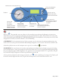
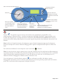
Appuyer sur . Le contrôleur effectue un auto-test (il allume rapidement ses voyants les uns après les autres
et fait momentanément retentir l'alarme), puis afche la température du liquide en recirculation. Ensuite, le
système de réfrigération et la pompe de recirculation démarrent. Le manomètre indiquant la PRESSION DE
RECIRCULATION afche la pression opératoire de la pompe. Si la pression doit être ajustée, consulter le chapitre
3 du manuel.
REMARQUE Si, au démarrage, le liquide en recirculation de l'appareil se situe en dehors de l'intervalle de
températures préconisé, l'appareil fonctionnera, mais le voyant approprié clignotera jusqu'à ce que le liquide se situe
entre les limites.
Pour afcher/modier le point de consigne, utiliser les touches èches, s'allume.
REMARQUE Si l'opérateur n'appuie pas sur les touches èches dans les 10 secondes qui suivent, la température
actuelle du réservoir se réafchera. Le contrôleur ne vous permettra pas d'entrer un point de consigne à moins de
2 °C de l'une ou l'autre limite d'alarme de température indiquée à la page suivante. Toute tentative d'utilisation d'un
point de consigne à moins de 2 °C engendre le clignotement du voyant approprié et le double retentissement de
l'alarme sonore.
Une fois le point de consigne souhaité afché, appuyer sur pour conrmer la modication. La nouvelle valeur
clignote rapidement et brièvement sur l'afchage, puis afche à nouveau la température du liquide en recirculation.
Appuyer sur ce
bouton pour mettre
l'appareil sous/
hors tension.
Indique l'état du système de réfrigération.
Indique que le
contrôleur affiche le
point de consigne.
Appuyer sur les
touches flèches pour
modifier la valeur.
Manomètre
Indique que le contrôleur
affiche le réglage d'alarme
de température basse.
Indique que le contrôleur
affiche le réglage d'alarme de
température haute.
Option. Indique que l'appareil
fonctionne en mode
communication série.
Appuyer ici pour modifier
la valeur affichée.
Appuyer ici pour faire défiler les
quatre voyants et accepter la
valeur affichée.
6
Page 2 sur 2

Pag. 1 van 2
Procesafvoer
1/2" FNPT messing
J1 Seriële communicatie
(optioneel)
Stroombescherming
Stroomingang
Procestoevoer
1/2" FNPT messing
DRAIN
1 Indien meegeleverd, verwijder de drain plug en
installeer de drain klep op de achterzijde van de koeler.
2 Sluit de PROCES AFVOER (A) aan op de
vloeistoftoevoer op uw toepassing. Sluit de PROCES
TOEVOER (B) aan op de vloeistofafvoer op uw
toepassing.
Zorg ervoor dat alle aansluitingen veilig zijn en dat
u het juiste afdichtmiddel/smeermiddel voor het
montagemateriaal gebruikt. (Als u Teon® tape gebruikt,
zorg er dan voor dat de tape niet over de eerste schroefdraad
wordt gewikkeld, omdat hij dan kan scheuren en in de
vloeistof terecht kan komen.)
Geschikte vloeistoffen zijn:
• Geltreerd/enkelvoudiggedestilleerdwater
• 0–75%ethyleenglycol/water
• 0–75%propyleenglycol/water
• Gedeïoniseerdwater(1-3MΩ-cm,
gecompenseerd)
Veiligheidsmaatregelen:
Deunitisalleenontworpenvoorgebruikbinnenshuis.
Plaatseenunitnooitopeenplekmetovermatigewarmte,vocht,onvoldoendeventilatieofcorrosievematerialen.
Gebruiknooitontvlambareofcorrosievevloeistoffenmetdezeunit.
Sluitnooitprocesvloeistoeidingenaanopdewatervoorzieningvanuwlocatieofanderevloeistofbronnenonderdruk.
Alsuwunitisuitgerustmeteenverdringerpomp(PD1ofPD2),zorgerdanvoordatdeleidingenenaansluitingenvanuwtoepassing
geschiktzijnvoorminimaal115psi.
Raadpleegvoordatuvloeistoffengebruiktofonderhouduitvoertopplekkenwaarwaarschijnlijkcontactismetvloeistof,de
veiligheidsbladenvandefabrikantvoorvoorzorgsmaatregelen.
3 Voordat de koeler wordt gevuld, zorg ervoor dat de drain klep of
drain plug op de achterzijde van de koeler goed gesloten zijn en dat de
slangen juist en goed zijn aangesloten.
Draai de twee duimschroeven los waarmee het reservoirdeksel aan de
unit bevestigd is. Controleer of het vloeistoflter goed op zijn plaats
in de onderkant van het reservoir zit. Vul de unit langzaam met schone
procesvloeistof tot aan de rand van het reservoir.
Aangezien de capaciteit van het reservoir klein kan zijn in vergelijking tot
uw toepassing en het nodig kan zijn dat er lucht uit de leidingen geblazen
moet worden, dient u extra koelvloeistof bij de hand te houden om het
systeem bijgevuld te houden als de uitwendige circulatie wordt gestart.
Als het reservoir niet tot aan de rand vol wordt gehouden, leidt dit tot
een lagere koelcapaciteit en mogelijke bevriezing van de blootgestelde
koperen koelspiraal.
Plaats het deksel van het reservoir terug en draai de duimschroeven aan.
Het deksel moet stevig dicht blijven om verdamping zoveel mogelijk te
beperken en om vuil uit het reservoir te houden.
Duimschroeven
Rand van reservoir
4 Controleer de juiste spanning. Steek het vrouwelijke uiteinde van het netsnoer in de stroomingang van de koeler en steek
vervolgens het mannelijke uiteinde van het netsnoer in een stopcontact.
5 Zet de circuitbeschermer omhoog; de controller knippert en het alarm klinkt kort. Zie de volgende pagina.
2
1
4
5
Deze Quick Start dient alleen gebruikt te worden voor het initieel opstarten van de unit.
Voor alle overige procedures verwijzen we u naar de gebruiksaanwijzing.

Druk op . De controller voert een zelftest uit (de controller loopt snel langs de ledlampjes en laat kort het
alarm horen) en geeft vervolgens de temperatuur van de recirculatievloeistof weer. Hierna starten het koelsysteem
en de recirculatiepomp. De RECIRCULATIEDRUKMETER geeft de bedrijfsdruk van de pomp weer. Als de druk
aangepast moet worden, zie dan Hoofdstuk 3 van de handleiding.
OPMERKING Als de recirculatievloeistof bij het opstarten van de unit buiten de temperatuurlimieten ligt, dan
werkt de unit wel, maar gaat het betreffende indicatielampje knipperen tot de vloeistof weer binnen de limiet is.
Gebruik de pijltjestoetsen om het instelpunt weer te geven/te veranderen. gaat branden.
OPMERKING Als u niet binnen 10 seconden op de pijltjestoetsen drukt, keert het display terug naar de huidige
reservoirtemperatuur. U kunt geen instelpunt invoeren dat dichter dan 2°C bij de temperatuuralarminstellingen ligt,
die op de volgende pagina worden besproken. Als u probeert om een instelpunt binnen 2°C te gebruiken, dan gaat
het betreffende lampje knipperen en klinkt het geluidsalarm tweemaal.
Als het gewenste instelpunt wordt weergegeven, drukt u op om de verandering te bevestigen. Het display geeft
de nieuwe waarde knipperend kort weer, en geeft dan de temperatuur van de recirculatievloeistof weer.
Gebruik deze toets
om de unit in of uit
te schakelen.
Geeft de status van het koelsysteem aan.
Geeft aan dat
de controller
het instelpunt
weergeeft. Druk op de
pijltjestoetsen om de
waarde te veranderen.
Drukmeter
Geeft aan dat de
controller de lage-
temperatuuralarminstelling
van de unit weergeeft.
Geeft aan dat de controller de
hoge-temperatuuralarminstelling
van de unit weergeeft.
Optioneel. Geeft aan
dat de unit in de seriële
communicatiemodus werkt.
Druk om de weergegeven
waarde te veranderen.
Druk om langs de vier
indicatielampjes te lopen en
de weergegeven waarde te
accepteren.
6
Pag. 2 van 2

Salida de líquido de proceso
FNPT bronce 1/2"
J1 de comunicación en serie
(opcional)
Protector del
circuito
Toma de
corriente
Entrada de líquido
de proceso
FNPT bronce 1/2"
DRAIN
Pueden utilizarse los siguientes líquidos:
Agua ltrada/destilada•
Etilenglicol/agua 0-75%•
Propilenglicol/agua 0-75% •
Agua desionizada (1-3 MΩ-cm, compensada)•
Precauciones de seguridad:
La unidad está destinada exclusivamente para uso en interiores.
No la coloque nunca en lugares con calor excesivo, humedad, ventilación inadecuada o presencia de
materiales corrosivos.
No utilice nunca líquidos inamables o corrosivos con esta unidad.
No conecte nunca tubos con líquido de proceso al suministro de agua del centro ni a ninguna fuente de líquido
presurizado.
Si la unidad está provista de una bomba de desplazamiento positivo (PD1 o PD2), asegúrese de que los tubos
y conectores de su aplicación tienen capacidad para soportar un mínimo de 115 psi.
Antes de utilizar líquidos o realizar tareas de mantenimiento en las que pueda entrar en contacto con ellos,
consulte las precauciones de manipulación en las chas de datos de seguridad del material (MSDS) del
fabricante.
3 Antes de rellenar, asegúrese que la válvula de drenaje (o el
tapón de drenaje) del tanque, en la parte posterior del refrigerador,
está cerrada y que todas las conexiones de fontanería son seguras.
lentamente la unidad
Ya que la capacidad del depósito puede ser pequeña para la
de refrigeración.
evaporación y evitar que entre suciedad en el depósito.
Tornillos de mariposa
Tapa del depósito
Página 1 de 2
4
5 Coloque el protector del circuito en la posición superior; el panel de
2
1
4
5
1
el tapón de drenaje e instalársela en la parte trasera del
refrigerador.
2Conecte la
a la entrada de líquido de la aplicación. Conecte la
a la salida
de líquido de la aplicación.
Esta guía de inicio rápido está diseñada solo para la puesta en marcha inicial. Para las otras
operaciones refiérase al manual.

NOTA
NOTA
recirculante.
Esta tecla sirve
para encender y
apagar la unidad.
Indica el estado del sistema de refrigeración.
Indica que el valor que
muestra actualmente el
panel de control es el
punto de ajuste. Pulse
las teclas de flecha para
cambiar el valor.
Manómetro
Indica que el valor que
muestra actualmente el
panel de control es el de
alarma de baja temperatura
de la unidad.
Indica que el valor que muestra
actualmente el panel de control es
el de alarma de alta temperatura.
Opcional. Indica que la
unidad funciona en modo de
comunicación en serie.
Sirven para cambiar el valor
que muestra la pantalla.
Sirven para alternar entre los
cuatro indicadores y aceptar el
valor de la pantalla.
6
Página 2 de 2

Uscita di processo
Ottone 1/2" FNPT
J1 Comunicazioni seriali
(Opzionale)
Protezione di circuito
Presa dell’alimentazione
Ingresso di
processo
Ottone 1/2" FNPT
1 Se presente, rimuovere il tappo dello scarico e
installare la valvola di drenaggio su retro del refrigeratore.
2 Collegare l'USCITA DI PROCESSO
all'ingresso liquidi dell'applicazione. Collegare l'INGRESSO
DI PROCESSO all'uscita liquidi dell'applicazione.
Assicurarsi che tutti i collegamenti siano ssati saldamente e
che venga utilizzato il sigillante/lubricante adatto al materiale
di cui sono fatti gli accessori. (Se si utilizza un nastro di
Teon®, assicurarsi che tale nastro non sporga sulla prima
lettatura poiché potrebbe slacciarsi e cadere nel liquido.)
Precauzioni di sicurezza:
Il refrigeratore è progettato esclusivamente per l'uso in ambienti chiusi.
Non posizionare mai il refrigeratore in un ambiente con temperature eccessivamente alte, umidità, ventilazione inadeguata o presenza di materiali corrosivi.
Non usare mai uidi corrosivi nel refrigeratore.
Non collegare le tubazioni dei liquidi di processo all'alimentazione d'acqua dell'impianto o a qualsiasi altra sorgente di liquido pressurizzato.
Se il refrigeratore è dotato di pompa volumetrica (PD1 o PF2), vericare che le tubazioni idrauliche e i raccordi previsti per l'applicazione siano
progettati per sostenere una pressione minima di 115 psi.
Prima di utilizzare liquidi o eseguire eventuali interventi di manutenzione che potrebbero implicare il contatto con il liquido, fare riferimento alle
schede di sicurezza dei materiali (MSDS) del produttore per le precauzioni d'uso.
3 Prima di procedere al riempimento, assicurarsi che lo scarico
del serbatoio o il tappo dello scarico sul retro del refrigeratore siano
chiusi e che tutti i collegamenti dei tubi siano ben ssati.
Allentare le due viti a testa zigrinata che ssano il coperchio del
serbatoio al refrigeratore. Assicurarsi che il ltro del liquido sia ssato
in posizione sul fondo del serbatoio. Riempire il serbatoio lentamente
con liquido di processo pulito no a raggiungere l'orlo.
Poiché la capacità del serbatoio potrebbe essere inferiore al necessario
per l'applicazione e potrebbe essere necessario spurgare l'aria dalle
tubazioni, tenere a portata di mano del liquido di raffreddamento
di riserva per rabboccare il sistema all'avvio del ricircolo esterno.
Mantenere sempre il corretto livello del liquido nel serbatoio no
alla parte superiore per evitare i rischi di perdità di capacità di
raffreddamento e di formazione di ghiaccio sulle serpentine di
raffreddamento in rame.
Riposizionare il coperchio del serbatoio e ssare le viti a testa zigrinata.
Il coperchio deve rimanere ssato al ne di ridurre al minimo
l'evaporazione e impedire alle impurità di entrare nel serbatoio.
Pagina 1 di 2
4 Vericare che la tensione sia adeguata. Inserire l'estremità femmina del cavo di
alimentazione nell'ingresso di alimentazione del refrigeratore, quindi inserire l'estremità
maschio del cavo di alimentazione in una presa di corrente.
5 Portare la protezione di circuito in posizione sollevata; il controller lampeggia e
l'allarme emette un suono. Vedere la pagina successiva.
1
2
4
5
I liquidi approvati sono:
• Acqua distillata/ltrata
• 0 - 75% etilenglicole/acqua per laboratorio
• 0 - 75% propilenglicole/acqua per laboratorio
• Acqua deionizzata (1 - 3 MΩ-cm, compensata)
Viti a testa zigrinata
Orlo del serbatoio
Scopo di questa guida rapida è facilitare la messa in funzione iniziale. Per tutte le altre procedure è necessario fare
riferimento al manuale. Se alcuni dei passaggi qui riportati non risultano chiari, leggere il manuale prima di proseguire.

Premere . Il controller esegue un autotest (il controller scorre rapidamente i propri LED e attiva
temporaneamente l'allarme acustico) e visualizza la temperatura del liquido di ricircolo. Vengono quindi avviati
il sistema di refrigerazione e la pompa di ricircolo. Il misuratore della PRESSIONE DI RICIRCOLO mostra la
pressione di esercizio della pompa. Qualora sia necessario regolare la pressione, fare riferimento alla sezione 3 del
manuale.
Nota Se all'avvio il liquido di ricircolo del refrigeratore supera i limiti di temperatura impostati, il refrigeratore
funziona comunque ma il relativo indicatore lampeggia no a quando la temperatura del liquido non rientra nei
limiti.
Per visualizzare/modicare il valore impostato usare i tasti freccia; si illumina.
Nota Se i tasti freccia non vengono premuti entro 10 secondi, il display torna alla visualizzazione della temperatura
corrente del serbatoio. Il controller non permetterà di impostare un valore che si avvicini per più di 2 °C a entrambi
i limiti di allarme della temperatura impostati. Se si tenta di utilizzare un valore che si avvicini per più di 2 °C,
l'indicatore inizierà a lampeggiare e l'allarme acustico suonerà due volte.
Una volta impostato il valore desiderato, premere per confermare la modica. Sul display compare,
lampeggiando velocemente, il nuovo valore che viene mostrato per un breve periodo per poi lasciare nuovamente
spazio alla visualizzazione della temperatura del liquido di ricircolo.
Usare questo
tasto per attivare/
disattivare il
refrigeratore.
Indica lo stato del sistema di refrigerazione.
Indica che il controller
sta visualizzando il valore
impostato. Premere i tasti
freccia per modificare il
valore.
Manometro
Indica che il controller sta
visualizzando l'impostazione
dell'allarme di temperatura
minima del refrigeratore.
Indica che il controller sta visualizzando
l'impostazione dell'allarme di
temperatura massima del refrigeratore.
Opzionale. Indica che il
refrigeratore sta lavorando
in modalità di comunicazione
seriale.
Premere per cambiare il
valore visualizzato.
Premere per scorrere i quattro
indicatori e accettare il valore
visualizzato.
6
Pagina 2 di 2

ThermoChill i
Thermo Scientific
Preface
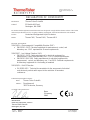
Compliance European Union - CE
The Declaration of Conformity is located in the back of
this manual.
WEEE This product is required to comply with the European Union’s Waste
Electrical & Electronic Equipment (WEEE) Directive 2012/19/EU. It is
marked with 'wheelie bin' symbol:
Thermo Fisher Scientic has contracted with one or more recycling/
disposal companies in each EU Member State, dispose of or recycle this
product through them. Further information on Thermo Fisher Scientic’s
compliance with these Directives is available at:
www.thermoscientic.com/WEEERoHS
After-sale Support Thermo Fisher Scientic is committed to customer service both during
and after the sale. If you have questions concerning the chiller operation,
or questions concerning spare parts or Service Contracts, call our Sales,
Service and Customer Support phone number, see this manual's inside
cover for contact information.
When calling, please refer to the labels on the inside cover. These labels list
all the necessary information needed to properly identify your chiller.
Feedback We appreciate any feedback you can give us on this manual. E-mail us at
tcmanuals@thermosher.com, please include the manual part number and
the revision date listed on the front cover.

ii ThermoChill
Preface
Thermo Scientific
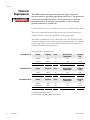
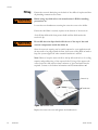
CAUTION
Warranty Thermo Scientic ThermoChills have a warranty against defective parts
and workmanship for 12 months from date of shipment. See back page
for more details.
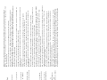
Unpacking The line cord it is located under the shipping crate’s lid. Do not discard
the lid until the cord is located. Retain all cartons and packing material
until the chiller is operating.
If the chiller shows external or internal damage contact the transportation
company and le a damage claim. Under ICC regulations, this is your
responsibility.
The chiller does not have handles. Take into account its weight,
90 or 160 pounds (41 or 73 kilograms), when unpacking and
transporting. We recommend using a harness when lifting the
chiller.
Out of Box Failure
An Out of Box Failure is dened as any product that fails to operate
in conformance with sellers published specications at initial power
up. Install the chiller in accordance with manufacturer's recommended
operating conditions within 30 days of shipment from the seller.
Any Temperature Control product meeting the denition of an Out of
Box Failure must be packed and shipped back in the original packaging
to Thermo Fisher Scientic for replacement with a new chiller; seller
to pay the cost of shipping. Customer must receive a Return Material
Authorization (RMA) from Thermo Fisher prior to shipping the chiller.
Pagina se încarcă...
Pagina se încarcă...
Pagina se încarcă...
Pagina se încarcă...
Pagina se încarcă...
Pagina se încarcă...
Pagina se încarcă...
Pagina se încarcă...
Pagina se încarcă...
Pagina se încarcă...
Pagina se încarcă...
Pagina se încarcă...
Pagina se încarcă...
Pagina se încarcă...
Pagina se încarcă...
Pagina se încarcă...
Pagina se încarcă...
Pagina se încarcă...
Pagina se încarcă...
Pagina se încarcă...
Pagina se încarcă...
Pagina se încarcă...
Pagina se încarcă...
Pagina se încarcă...
Pagina se încarcă...
Pagina se încarcă...
Pagina se încarcă...
Pagina se încarcă...
Pagina se încarcă...
Pagina se încarcă...
Pagina se încarcă...
Pagina se încarcă...
Pagina se încarcă...
Pagina se încarcă...
Pagina se încarcă...
Pagina se încarcă...
Pagina se încarcă...
Pagina se încarcă...
Pagina se încarcă...
Pagina se încarcă...
Pagina se încarcă...
Pagina se încarcă...
Pagina se încarcă...
Pagina se încarcă...
Pagina se încarcă...
Pagina se încarcă...
Pagina se încarcă...
Pagina se încarcă...
Pagina se încarcă...
Pagina se încarcă...
Pagina se încarcă...
Pagina se încarcă...
Pagina se încarcă...
Pagina se încarcă...
Pagina se încarcă...
Pagina se încarcă...
Pagina se încarcă...
Pagina se încarcă...
Pagina se încarcă...
Pagina se încarcă...
Pagina se încarcă...
Pagina se încarcă...
Pagina se încarcă...
Pagina se încarcă...
Pagina se încarcă...
Pagina se încarcă...
Pagina se încarcă...
Pagina se încarcă...
Pagina se încarcă...
Pagina se încarcă...
Pagina se încarcă...
Pagina se încarcă...
Pagina se încarcă...
Pagina se încarcă...
Pagina se încarcă...
Pagina se încarcă...
Pagina se încarcă...
Pagina se încarcă...
Pagina se încarcă...
Pagina se încarcă...
Pagina se încarcă...
Pagina se încarcă...
Pagina se încarcă...
Pagina se încarcă...
Pagina se încarcă...
Pagina se încarcă...
Pagina se încarcă...
Pagina se încarcă...
Pagina se încarcă...
Pagina se încarcă...
Pagina se încarcă...
Pagina se încarcă...
Pagina se încarcă...
Pagina se încarcă...
Pagina se încarcă...
Pagina se încarcă...
Pagina se încarcă...
Pagina se încarcă...
Pagina se încarcă...
Pagina se încarcă...
Pagina se încarcă...
Pagina se încarcă...
Pagina se încarcă...
Pagina se încarcă...
Pagina se încarcă...
Pagina se încarcă...
-
 1
1
-
 2
2
-
 3
3
-
 4
4
-
 5
5
-
 6
6
-
 7
7
-
 8
8
-
 9
9
-
 10
10
-
 11
11
-
 12
12
-
 13
13
-
 14
14
-
 15
15
-
 16
16
-
 17
17
-
 18
18
-
 19
19
-
 20
20
-
 21
21
-
 22
22
-
 23
23
-
 24
24
-
 25
25
-
 26
26
-
 27
27
-
 28
28
-
 29
29
-
 30
30
-
 31
31
-
 32
32
-
 33
33
-
 34
34
-
 35
35
-
 36
36
-
 37
37
-
 38
38
-
 39
39
-
 40
40
-
 41
41
-
 42
42
-
 43
43
-
 44
44
-
 45
45
-
 46
46
-
 47
47
-
 48
48
-
 49
49
-
 50
50
-
 51
51
-
 52
52
-
 53
53
-
 54
54
-
 55
55
-
 56
56
-
 57
57
-
 58
58
-
 59
59
-
 60
60
-
 61
61
-
 62
62
-
 63
63
-
 64
64
-
 65
65
-
 66
66
-
 67
67
-
 68
68
-
 69
69
-
 70
70
-
 71
71
-
 72
72
-
 73
73
-
 74
74
-
 75
75
-
 76
76
-
 77
77
-
 78
78
-
 79
79
-
 80
80
-
 81
81
-
 82
82
-
 83
83
-
 84
84
-
 85
85
-
 86
86
-
 87
87
-
 88
88
-
 89
89
-
 90
90
-
 91
91
-
 92
92
-
 93
93
-
 94
94
-
 95
95
-
 96
96
-
 97
97
-
 98
98
-
 99
99
-
 100
100
-
 101
101
-
 102
102
-
 103
103
-
 104
104
-
 105
105
-
 106
106
-
 107
107
-
 108
108
-
 109
109
-
 110
110
-
 111
111
-
 112
112
-
 113
113
-
 114
114
-
 115
115
-
 116
116
-
 117
117
-
 118
118
-
 119
119
-
 120
120
-
 121
121
-
 122
122
-
 123
123
-
 124
124
-
 125
125
-
 126
126


Thermo Fisher Scientific ThermoChill Series, ThermoChill LR Series Recirculating Chillers Manual de utilizare
- Tip
- Manual de utilizare
în alte limbi
- français: Thermo Fisher Scientific ThermoChill Series, ThermoChill LR Series Recirculating Chillers Manuel utilisateur
- English: Thermo Fisher Scientific ThermoChill Series, ThermoChill LR Series Recirculating Chillers User manual
- eesti: Thermo Fisher Scientific ThermoChill Series, ThermoChill LR Series Recirculating Chillers Kasutusjuhend
- italiano: Thermo Fisher Scientific ThermoChill Series, ThermoChill LR Series Recirculating Chillers Manuale utente
Lucrări înrudite
-
 Thermo Fisher Scientific Merlin LR Recirculating Chiller Quick Start
-
 Thermo Fisher Scientific ThermoFlex Recirculating Chillers Manual de utilizare
-
 Thermo Fisher Scientific Accel Series Cooling/Heating Recirculating Chillers Manual de utilizare
-
 Thermo Fisher Scientific Merlin M75 Recirculating Chiller Quick Start
-
 Thermo Fisher Scientific Precision Water Baths Ghid de inițiere rapidă
-
 Thermo Fisher Scientific Horizon PC-FTS Fogging Test Unit Manual de utilizare
-
 Thermo Fisher Scientific Immersion Circulators & Bath Circulators Advanced U01152 Manual de utilizare
-
 Thermo Fisher Scientific Horizon AC-FTS Fogging Test Unit Manual de utilizare
-
 Thermo Fisher Scientific VersaCool Manual de utilizare
-
 Thermo Fisher Scientific EK20/EK30 Immersion Coolers Manual de utilizare


