Riello RESIDENCE HM 30 KIS Manual de utilizare
- Tip
- Manual de utilizare

RESIDENCE HM
EN INSTRUCTIONS FOR THE USER, THE INSTALLER AND FOR THE TECHNICAL ASSISTANCE SERVICE
RO,16758&܉,81,3(175887,/,=$725,167$/$725܇,3(17586(59,&,8/'($6,67(1܉Ă7(+1,&Ă
EL ȅǻǾīǿǼȈīǿǹȉȅȃȋȇǾȈȉǾȉȅȃǼīȀǹȉǹȈȉǹȉǾȀǹǿīǿǹȉǾȃȊȆǾȇǼȈǿǹȉǼȋȃǿȀǾȈǺȅǾĬǼǿǹȈ

2
0476
EN 1
Warnings and safety 3
2
Description 3
3
Technical data 4
4
Installation 7
5
Commissioning 12
6
Maintenance and cleaning 18
7
Control panel 23
8
User instructions 24
9
General section 76
10
Setting password, access and
SDUDPHWHUPRGL¿FDWLRQ 82
EL 1
ȆȡȠİȚįȠʌȠȚȒıİȚȢțĮȚĮıijȐȜİȚĮ 51
2
ȆİȡȚȖȡĮijȒ 51
3
ȉİȤȞȚțȐȋĮȡĮțIJȘȡȚıIJȚțȐ 52
4
ǼȖțĮIJȐıIJĮıȘ 55
5
ĬȑıȘıİȜİȚIJȠȣȡȖȓĮ 60
6
ȈȣȞIJȒȡȘıȘțĮȚțĮșĮȡȚıȝȩȢ 66
7
ȆȓȞĮțĮȢİȜȑȖȤȠȣ 72
8
ȅįȘȖȓİȢȤȡȒıȘȢ 73
9
īİȞȚțȒİȞȩIJȘIJĮ 76
10
ȇȣșȝȓıİȚȢțȦįȚțȠȪʌȡȩıȕĮıȘȢțĮȚ
IJȡȠʌȠʌȠȓȘıȘȢʌĮȡĮȝȑIJȡȦȞ
82
RO 1
$YHUWLVPHQWHʓLPăVXULGHVLJXUDQʕă 27
2
Descriere 27
3
Date tehnice 28
4
Instalare 31
5
3XQHUHDvQIXQFʕLXQH 36
6
ÌQWUHʕLQHUHʓLFXUăʕDUH 42
7
3DQRXGHFRPDQGă 47
8
,QVWUXFʕLXQLGHXWLOL]DUH 48
9
6HFʕLXQHDJHQHUDOă 76
10
Introducerea parolei (password),
DFFHVXOʓLPRGL¿FDUHDSDUDPHWULORU 82
RESIDENCE HM KIS boiler complies with basic requi-
rements of the following Directives:
- Regulation (UE) 2016/426
-(I¿FLHQF\GLUHFWLYH$UWLFOHDQG$QQH[,,,RIGL-
rective 92/42/EEC
- Electromagnetic compatibility directive 2014/30/EU
- Low-voltage directive 2014/35/EU
- Directive 2009/125/EC Ecodesign for energy-using
appliances
- Regulation (EU) 2017/1369 Energy labeling
- Delegated Regulation (EU) No. 811/2013
- Delegated Regulation (EU) No. 813/2013.
ȅȜȑȕȘIJĮȢRESIDENCE HM KISıȣȝȝȠȡijȫȞİIJĮȚȝİ
IJȚȢȠȣıȚȫįȘȢĮʌĮȚIJȒıİȚȢIJȦȞʌĮȡĮțȐIJȦȅįȘȖȚȫȞ
-ȀĮȞȠȞȚıȝȩȢǼǼ
-ȅįȘȖȓĮĮʌȠįȩıİȦȞǼȓįȠȢțĮȚȆĮȡȐȡIJȘȝĮ,,,
IJȘȢǼȅȀ
-ȅįȘȖȓĮȘȜİțIJȡȠȝĮȖȞȘIJȚțȒȢıȣȝȕĮIJȩIJȘIJĮȢ
ǼǼ
-ȅįȘȖȓĮȤĮȝȘȜȒȢIJȐıȘȢǼȀ
-ȅįȘȖȓĮǼȀȅȚțȠȜȠȖȚțȠȪıȤİįȚĮıȝȠȪIJȦȞ
ʌȡȠȧȩȞIJȦȞʌȠȣıȣȞįȑȠȞIJĮȚȝİIJȘȞİȞȑȡȖİȚĮ
-ȀĮȞȠȞȚıȝȩȢǼǼǼIJȚțȑIJĮİȞȑȡȖİȚĮȢ
-ȀĮIJ¶İȟȠȣıȚȠįȩIJȘıȘțĮȞȠȞȚıȝȩȢǼǼĮȡ
-ȀĮIJ¶İȟȠȣıȚȠįȩIJȘıȘțĮȞȠȞȚıȝȩȢǼǼĮȡ
&HQWUDODWHUPLFăRESIDENCE HM KISUHVSHFWăFHU-
LQĠHOHGHED]ăDOHXUPăWRDUHORUGLUHFWLYH:
- Regulamentul (UE) 2016/426
-'LUHFWLYDGHH¿FLHQĠă$UWLFROXOúLDQH[D,,,GLQGL-
rectiva 92/42/CEE
-'LUHFWLYD GH FRPSDWLELOLWDWH HOHFWURPDJQHWLFă
2014/30/UE
- Directiva 2014/35/UE privind echipamentele de
MRDVăWHQVLXQH
-'LUHFWLYD8(SULYLQGFHULQĠHOHGHSURLHF-
WDUHHFRORJLFăDSOLFDELOHDSDUDWHORUFRQVXPDWRDUH
de energie
- Regulamentul (UE) 2017/1369 Etichetarea energiei
-5HJOHPHQWDUHGHOHJDWă8(QU
-5HJOHPHQWDUHGHOHJDWă8(QU.
0476 0476
In some parts of the booklet, some symbols are
used:
Section destined for user also.
b
WARNING = for actions requiring spe-
cial care and adequate preparation.
a
PROHIBITED = for actions THAT MUST
NOT be performed.
ȈIJȠ İȖȤİȚȡȓįȚȠ ȤȡȘıȚȝȠʌȠȚȠȪȞIJĮȚ IJĮ ĮțȩȜȠȣșĮ
ıȪȝȕȠȜĮ
:
ȂȑȡȠȢ ʌȠȣ ʌȡȠȠȡȓȗİIJĮȚ țĮȚ ȖȚĮ IJȠȞ ȤȡȒ-
ıIJȘ
.
b
ȆȇȅȈȅȋǾ ȖȚĮ İȞȑȡȖİȚİȢ ʌȠȣ ĮʌĮȚIJȠȪȞ
ȚįȚĮȓIJİȡȘ ʌȡȠıȠȤȒ țĮȚ țĮIJȐȜȜȘȜȘ ʌȡȠİ-
IJȠȚȝĮıȓĮ
.
a
ǹȆǹīȅȇǼȊǼȉǹǿ ȖȚĮ İȞȑȡȖİȚİȢ ʌȠȣ
ǹȆǹīȅȇǼȊȅȃȉǹǿ ĮȣıIJȘȡȐ
.
WARNING
This instructions manual contains data
and information for both the user and
WKH LQVWDOOHU 6SHFL¿FDOO\ QRWH WKDW WKH
user, for the use of the appliance, must
refer to chapters: Warnings and safety
• Commissioning • Maintenance.
b
The user must not perform operations
on the safety devices, replacing parts of
the product, tamper with or attempt to
repair the appliance. These operations
must be entrusted exclusively
SURIHVVLRQDOO\ TXDOL¿HG SHUVRQQHO.
a
The manufacturer is not liable for
any damage caused by the non-
observance of the above and/or the
failure to comply with the regulations
.
ȆȇȅǼǿǻȅȆȅǿǾȈǾ
ǹȣIJȩ IJȠ ȕȚȕȜȚĮȡȐțȚ ʌİȡȚȑȤİȚ įİįȠȝȑȞĮ țĮȚ ʌȜȘ-
ȡȠijȠȡȓİȢ ʌȠȣ ʌȡȠȠȡȓȗȠȞIJĮȚ IJȩıȠ ȖȚĮ IJȠ ȤȡȒıIJȘ
ȩıȠ țĮȚ ȖȚĮ IJȠȞ İȖțĮIJĮıIJȐIJȘ
ȆȚȠ ıȣȖțİțȡȚȝȑȞĮ Ƞ ȤȡȒıIJȘȢ ʌȡȑʌİȚ ȞĮ
įȫıİȚ ȚįȚĮȓIJİȡȘ ıȘȝĮıȓĮ ıIJĮ țİijȐȜĮȚĮ
ȆȡȠİȚįȠʌȠȚȒıİȚȢ țĮȚ ĮıijȐȜİȚĮ
•
ĬȑıȘ ıİ
ȜİȚIJȠȣȡȖȓĮ
•
ȈȣȞIJȒȡȘıȘ
.
b
ȅ ȤȡȒıIJȘȢ įİȞ ʌȡȑʌİȚ ȞĮ ʌĮȡİȝȕĮȓȞİȚ ıIJĮ
ıȣıIJȒȝĮIJĮ ĮıijĮȜİȓĮȢ ȞĮ ĮȞIJȚțĮșȚıIJȐ ȝȑȡȘ
IJȠȣ ʌȡȠȧȩȞIJȠȢ ȞĮ țȐȞİȚ IJȡȠʌȠʌȠȚȒıİȚȢ țĮȚ ȞĮ
ʌȡȠıʌĮșİȓ ȞĮ İʌȚıțİȣȐıİȚ IJȘ ıȣıțİȣȒ ǹȣIJȑȢ
ȠȚ İȡȖĮıȓİȢ ʌȡȑʌİȚ ȞĮ ȗȘIJİȓIJĮȚ ȞĮ ȖȓȞȠȞIJĮȚ
ĮʌȠțȜİȚıIJȚțȐ țĮȚ ȝȩȞȠ Įʌȩ İȚįȚțİȣȝȑȞȠ
İʌĮȖȖİȜȝĮIJȚțȩ ʌȡȠıȦʌȚțȩ
.
a
ȅ țĮIJĮıțİȣĮıIJȒȢ įİȞ ijȑȡİȚ țĮȝȓĮ İȣșȪȞȘ ȖȚĮ
IJȣȤȩȞ ȗȘȝȚȑȢ ʌȠȣ ȠijİȓȜȠȞIJĮȚ ıİ ȝȘ ıȣȝȝȩȡijȦıȘ
ȝİ IJĮ ʌĮȡĮʌȐȞȦ
.
AVERTISMENT
3UH]HQWXO PDQXDO GH LQVWUXFĠLXQL
FRQĠLQH GDWH úL LQIRUPDĠLL GHVWLQDWH
DWkW XWLOL]DWRUXOXL FkW úL LQVWDODWRUXOXL
ÌQ PRG VSHFL¿F UHĠLQHĠL Fă XWLOL]DWRUXO
SHQWUX XWLOL]DUHD DSDUDWXOXL WUHEXLH
Vă VH UHIHUH OD FDSLWROH: Avertismente
úL PăVXUL GH VLJXUDQĠă • 3XQHUHD vQ
IXQFĠLXQH • ÌQWUHĠLQHUH.
b
8WLOL]DWRUXO QX WUHEXLH Vă LQWHUYLQă
DVXSUD GLVSR]LWLYHORU GH VLJXUDQĠă úL
QLFL Vă vQORFXLDVFă SăUĠL DOH SURGXVXOXL
Vă GHVIDFă VDX Vă vQFHUFH Vă UHSDUH
DSDUDWXO $FHVWH RSHUDĠLL WUHEXLH Vă ¿H
vQFUHGLQĠDWH H[FOXVLY XQRU SHUVRDQH
FDOL¿FDWH SURIHVLRQDO.
a
3URGXFăWRUXO QX vúL DVXPă UăVSXQGHUHD
SHQWUX HYHQWXDOHOH GDXQH FDX]DWH GH
QHUHVSHFWDUHD LQGLFDĠLLORU GH PDL VXV
úLVDX D QRUPHORU vQ YLJRDUH
.
ÌQ DQXPLWH VHFĠLXQL DOH PDQXDOXOXL VXQW XWLOL-
]DWH VLPEROXULOH:
6HFĠLXQH GHVWLQDWă GH DVHPHQHD SHQWUX
XWLOL]DWRU.
b
$7(1ğ,( SHQWUX DFĠLXQL FDUH QHFHVLWă
R DWHQĠLH GHRVHELWă úL R SUHJăWLUH
FRUHVSXQ]ăWRDUH.
a
INTERZIS SHQWUX DFĠLXQL FDUH 18
75(%8,( Vă ¿H HIHFWXDWH.
XXXXXXXX - code:
00000000
SERIAL:
000000000000
P/C:
000000000000000000000
EN Activate the warranty: scan the QR code on the product or go
to “www.myeasycomfort.com”
RO $FWLYDʕLJDUDQʕLDVFDQDʕLFRGXO45GHSHSURGXVVDXDFFH-
VDʕL³ZZZP\HDV\FRPIRUWFRP´
EL
ǼȞİȡȖȠʌȠȚȒıIJİ IJȘȞ İȖȖȪȘıȘ ıĮȡȫıIJİ IJȠȞ țȦįȚțȩ 45 ıIJȠ
ʌȡȠȧȩȞȒȝİIJĮȕİȓIJİıIJȘįȚİȪșȣȞıȘ³ZZZP\HDV\FRPIRUWFRP´

3
1 WARNINGS AND SAFETY
b
The boilers manufactured in our factories are checked
even in the smallest details in order to protect users
and installers against possible injury. After working on
WKHSURGXFWTXDOL¿HGSHUVRQQHOPXVWFKHFNWKHHOHF-
trical wiring, in particular the stripped part of leads,
which must not protrude from the terminal board and
avoiding possible contact with live parts of the leads
themselves.
b
This manual is an integral part of the product: make
sure it is always kept with the appliance, even if
the latter is transferred to another owner or user, or
moved to another heating system. In case of loss or
damage, please contact your local Technical Assis-
tance Centre for a new copy.
b
This appliance should not be operated by children un-
der the age of 8, people with reduced physical, sen-
sory or mental capacities, or inexperienced people
who are not familiar with the product, unless they are
given close supervision or instructions on how to use
it safely and are made aware by a responsible person
of the dangers its use might entail. Children must not
play with the appliance. It is the user's responsibility
to clean and maintain the appliance. Children should
never clean or maintain it unless they are supervised.
b
Boiler installation and any other assistance and main-
WHQDQFH RSHUDWLRQ PXVW EH FDUULHG RXW E\ TXDOL¿HG
personnel according to the current regulations and in
compliance with UNI 7129-7131 and updates.
b
Boiler maintenance must be performed at least once
a year and scheduled in good time with the Technical
Service Centre.
b
The installer must instruct the user about how the ap-
pliance works, and the essential safety rules.
b
The user must respect the warnings given in this
manual.
b
This boiler is intended for the use for which it was ex-
pressly designed. The manufacturer accepts no con-
tractual or non-contractual liability for any damage or
harm caused to people, animals and property due to
installation, adjustment and maintenance errors or to
improper use.
b
After removing the packaging, make sure the con-
tents are in good condition and complete. Otherwise,
contact the dealer from who you purchased the ap-
pliance.
b
The safety valve outlet must be connected to a suita-
ble collection and venting system. The manufacturer
disclaims liability for any damage caused by the inter-
vention of the safety valve.
b
Dispose of all the packaging materials in the relative
containers at the corresponding collection centres.
b
When disposing of waste, be careful not to harm hu-
man health or employ procedures or methods which
may damage the environment.
At the end of its life, the product should be not be
disposed of as solid urban waste, but rather it should
EH KDQGHG RYHU WR D GLႇHUHQWLDWHG ZDVWH FROOHFWLRQ
centre.
Duri
ng installation, the user must be informed that:
- in the event of water leakage, the water supply must be
VKXW Rႇ DQG WKH 7HFKQLFDO$VVLVWDQFH &HQWUH PXVW EH
QRWL¿HGZLWKRXWGHOD\
- the operating pressure of the hydraulic system must be
checked regularly to ensure it is higher than 1 bar. If
QHFHVVDU\UHVWRUHSUHVVXUHE\RSHQLQJWKH¿OOLQJWDS (the
operating pressure of the hydraulic system must be checked
regularly to ensure it is higher than 1 bar. If necessary,
UHVWRUHSUHVVXUHE\RSHQLQJWKH¿OOLQJWDSsection 9 - see
“Boiler layout” -
1
)
-wait for the pressure to increase: check on the boiler
display that the value reaches 1-1.5 bar; then close the
¿OOLQJWDS
section 9 - see “Boiler layout”
).
If the boiler is not used for a long time, you are advised to
carry out the following operations:
- set the device to OFF and the main switch of the system
WRRႇ
- close the gas and water taps on both the heating and
domestic hot water circuits
- empty the heating and DHW system if there is a risk of
freezing.
For reasons of safety remember that:
a
It is forbidden to activate electric devices or applianc-
es such as switches, household appliances and so
on if you notice a smell of fuel or unburnt fuel. In this
case:
- ventilate the room by opening the doors and win-
dows;
- FORVHWKHIXHOVKXWRႇGHYLFH;
- arrange for the Technical Assistance Centre or pro-
IHVVLRQDOO\TXDOL¿HGSHUVRQQHOWRLQWHUYHQHSURPSWO\.
a
It is forbidden to touch the appliance while barefoot or
if parts of your body are wet.
a
It is strictly prohibited to carry out any technical or
cleaning work before disconnecting the appliance
from the power supply by placing the boiler to “OFF”
and the also setting the main switch of the system to
“OFF”.
a
Do not modify the safety or adjustment devices with-
out the manufacturer’s authorisation and precise in-
structions.
a
It is forbidden to pull, detach or twist the electrical
cables from the appliance, even if it is disconnected
from the mains supply.
a
Do not cover or reduce the size of the ventilation
openings in the room where the boiler is installed.
a
,WLVIRUELGGHQWROHDYHÀDPPDEOHFRQWDLQHUVDQGVXE-
stances in the room where the appliance is installed.
a
It is forbidden to leave the packaging material within
children's reach, as it may be a potential source of
danger. Dispose of it responsibly, in accordance with
the legislation in force.
a
It is forbidden to obstruct the condensate drain outlet.
The condensate drain pipe should be facing the dis-
charge pipe, preventing the formation of further drain
pipes.
a
It is forbidden to intervene in any way on the gas
valve.
a
It is forbidden to intervene on sealed elements.
2 DESCRIPTION
RESIDENCE HM
boilers have a new ACC (active combustion control)
combustion control system. This innovative control system, developed
E\ 5LHOOR JXDUDQWHHV IXQFWLRQDOLW\ HႈFLHQF\ DQG ORZ HPLVVLRQV LQ DOO
circumstances. The ACC system uses an ionization sensor immersed in
WKHEXUQHUÀDPHZKLFKWKURXJKLWVLQIRUPDWLRQDOORZVWKHFRQWUROERDUG
to act on the gas valve that regulates the fuel. This sophisticated control
system allows self-regulation of combustion, eliminating the need for ini-
tial calibration. The ACC system is able to adapt the boiler to operate with
GLႇHUHQWJDVFRPSRVLWLRQVGLႇHUHQWSLSHOHQJWKVDQGGLႇHUHQWDOWLWXGHV
(within the expected design limits). The ACC system is also able to carry
out a self-diagnosis which blocks the burner before exceeding emission
thresholds higher than the limits allowed by the regulations.

4
3 TECHNICAL DATA
DESCRIPTION UM 25 HM KIS 30 HM KIS 35 HM KIS
G20 G31 G20 G31 G20 G31
Heating
Rated heat input kW-kcal/h 20,00-17.200 25,00-21.500 30,00-25.800
Nominal heat output (80°/60°) kW-kcal/h 19,53-16.799 24,42-20.997 29,28-25.181
Nominal heat output (50°/30°) kW-kcal/h 21,31-18.323 26,51-22.799 31,75-27.302
Reduced heat input kW-kcal/h 2,50-2.150 - 3,00-2.580 3,50-3.010 3,50-3.010 -
Reduced heat output (80°/60°) kW-kcal/h 2,34-2.009 - 2,87-2.465 3,30-2.841 3,36-2.891 -
Reduced heat output (50°/30°) kW-kcal/h 2,57-2.213 - 3,19-2.743 3,65-3.142 3,71-3.191 -
DHW
Rated heat input kW-kcal/h 25,00-21.500
I2Y20: 24,00-20.640 30,00-25.800 34,90-30.014
Nominal heat output (*) kW-kcal/h 25,00-21.500 30,00-25.800 34,90-30.014
Reduced heat input kW-kcal/h 2,50-2.150 - 3,00-2.580 3,50-3.010 3,50-3.010 -
Reduced heat output (*) kW-kcal/h 2,50-2.150 - 3,00-2.580 3,50-3.010 3,50-3.010 -
8VHIXOHႈFLHQF\3QPD[3QPLQ %97,7-93,5 97,7-95,5 97,6-96,0
&RPEXVWLRQHႈFLHQF\ %98,0 97,9 97,8
8VHIXOHႈFLHQF\3QPD[3QPLQ %106,5-102,9 106,0-106,3 105,8-106,0
8VHIXOHႈFLHQF\3QPD[UHWXUQ %108,8 108,8 108,7
Total electric power (max power HEATING - DHW.) W 73-87 74-87 87-110
Circulator electric power (1.000 l/h) W 43 43 43
Category
Ɣ
Country of destination
,,+<3Ɣ ,,+<3Ɣ ,,+<3Ɣ
3RZHUVXSSO\YROWDJH V-Hz 230-50 230-50 230-50
3URWHFWLRQOHYHO ,3 X5D X5D X5D
Heat loss on shut-down W 30 35 35
/RVVHVDWWKHÀXHZLWKEXUQHURႇRQ %0,09-2,04 0,08-2,07 0,07-2,17
Heating operation
Maximum pressure bar 333
Minimum pressure for standard operation bar 0,25÷0,45 0,25÷0,45 0,25÷0,45
Maximum temperature °C 90 90 90
6HOHFWLRQ¿HOGRIKHDWLQJH2O temperature °C 40-80 (high)
20-45 (low) 40-80 (high)
20-45 (low) 40-80 (high)
20-45 (low)
3XPSPD[LPXPGLVFKDUJHKHDGDYDLODEOHIRUWKHV\VWHP mbar 450 450 450
DWDÀRZUDWHRI l/h 1.000 1.000 1.000
Membrane expansion vessel l 999
Expansion tank pre-loading (heating) bar 111
DHW operation
Maximum pressure bar 888
Minimum pressure bar 0,5 0,5 0,5
Quantity of hot water withǻW& l/min 14,3 17,2 20,0
withǻW& l/min 11,9 14,3 16,7
withǻW& l/min 10,2 12,3 14,3
DHW minimum output l/min 222
6HOHFWLRQ¿HOGRI'+:H2O temperature °C 37-60 37-60 37-60
Flow regulator l/min 10 12 14
Gas pressure
Nominal natural gas pressure (G20 - I2H) mbar 20 - - 20 - - 20 - -
Nominal MTN-H pressure (G20.2 - I2Y20) mbar -20 - -20 - -20 -
1RPLQDO/3*SUHVVXUH*,3 mbar -- 37 -- 37 -- 37
Heating
ÀRZUDWH
G20 G31 G20 G31 G20 G31
$LUÀRZUDWH Nm
3
/h
24,804 24,819 31,005 31,317 37,206 37,581
)OXHJDVÀRZUDWH Nm
3
/h 26,811 26,370 33,513 33,256 40,216 39,908
0DVVÀXHJDVÀRZUDWHPD[PLQ g/s 9,267-1,158 9,297-1,162 11,584-1,390 11,726-1,627 13,900-1,622 14,072-1,627
'+:ÀRZUDWH
G20 G31 G20 G31 G20 G31
$LUÀRZUDWH Nm
3
/h
31,005 31,024 37,206 37,581 43,284 43,719
)OXHJDVÀRZUDWH Nm
3
/h 33,513 32,963 40,216 39,908 46,784 46,426
0DVVÀXHJDVÀRZUDWHPD[PLQ g/s 11,584-1,158 11,621-1,162 13,900-1,390 14,072-1,627 16,171-1,622 16,370-1,627
Fan performance
Residual discharge head of concentric pipes 0.85 m 3D 60 60 60
Residual discharge head of separate pipes 0.5 m 3D 180 195 195
Residual discharge head of boiler without pipes 3D 186 199 199
Nox
class 6 class 6 class 6
Maximum permissible emission value (**) G20 G31 G20 G31 G20 G31
Qn-Qr CO (0% O2) less than p.p.m. 230-15 250-20 200-15 250-20 240-15 240-20
CO2 (***) %8,8-8,8 10,0-10,0 8,8-8,8 9,9-10,0 8,8-8,8 9,9-10,0
NOx (0% O2) less than p.p.m. 40-30 50-50 30-30 40-40 30-30 40-40
Flue gas T °C 79-60 78-60 71-57 70-57 82-60 70-57
O2 value relative to the
20% hydrogen mixture
Qmax
max % 2,4 2,4 2,4
nominal % 4,3 4,3 4,3
min % 6,2 6,2 6,2
Qmin
max % 2,4 2,4 2,4
nominal % 4,3 4,3 4,3
min % 6,2 6,2 6,2
(*) Average value of various hot water operating conditions
(**) Test carried out with Ø60-100 concentric pipe, length 0.85m. - in heating, water temperature 80-60°C - values measured with the casing completely closed
(***) Tolerance CO2= ±1%
7KHLQVWDOODWLRQRIWKLVSURGXFWLVDOORZHGRQO\LQWKHGHVWLQDWLRQ&RXQWULHVFRQWDLQHGLQWKHGDWDSODWHUHJDUGOHVVRIWKHSUHVHQWWUDQVODWLRQODQJXDJH
7KHGDWDH[SUHVVHGPXVWQRWEHXVHGWRFHUWL¿FDWHWKHV\VWHPIRUFHUWL¿FDWLRQXVHWKHGDWDLQGLFDWHGLQWKH³6\VWHPKDQGERRN´PHDVXUHGGXULQJ¿UVWLJQLWLRQ

5
PARAMETERS
UM
METHANE GAS
(G20)
LPG
(G31)
Lower Wobbe index (at 15°C-1013 mbar) MJ/m³S 45,67 70,69
1HWFDORUL¿FYDOXH MJ/m³S 34,02 88
1RPLQDOVXSSO\SUHVVXUH mbar (mm H2O) 20 (203,9) 37 (377,3)
0LQLPXPVXSSO\SUHVVXUH mbar (mm H2O) 13 (132,6) -
25
HM KIS
30
HM KIS
35
HM KIS
25
HM KIS
30
HM KIS
35
HM KIS
%XUQHUGLDPHWHUOHQJWK mm 70/80,5 70/95 70/95 70/80,5 70/95 70/95
0D[LPXPJDVÀRZUDWHKHDWLQJ 6PñK 2,12 2,64 3,17 - - -
NJK - - - 1,55 1,94 2,33
0D[LPXPJDVÀRZUDWH'+: 6PñK 2,64 3,17 3,69 - - -
NJK - - - 1,94 2,33 2,71
0LQLPXPJDVÀRZUDWHKHDWLQJ 6PñK 0,26 0,32 0,37 - - -
NJK - - - 0,19 0,27 0,27
0LQLPXPJDVÀRZUDWH'+: 6PñK 0,26 0,32 0,37 - - -
NJK - - - 0,19 0,27 0,27
0D[LPXPQXPEHURIIDQURWDWLRQVKHDWLQJ USP 6.300 6.200 7.400 6.100 5.800 7.100
0D[LPXPQXPEHURIIDQURWDWLRQV'+: USP 7.900 7.400 8.600 7.600 7.100 8.200
0LQLPXPQXPEHURIIDQURWDWLRQVKHDWLQJ'+: USP 1.200 1.200 1.300 1.250 1.250 1.250
Max.
QURIIDQ
URWDWLRQVKHDWLQJ in C(10)3 FRQ¿JXUDWLRQƔ USP 6.500 6.400 7.600 - - -
Max.
QURIIDQ
URWDWLRQV'+: in C(10)3 FRQ¿JXUDWLRQƔ USP 8.100 7.600 8.600 - - -
0LQQURIIDQURWDWLRQVKHDWLQJ'+: in C(10)3 FRQ¿JXUDWLRQƔ
USP 2.100 2.200 2.200 - - -
NOTE:LQWKH¿UVWKRXUVRIEXUQHURSHUDWLRQWKHPLQLPXPZLOOQHYHUJREHORZUSPIRUERWKWKHDQGN:USPLI/3*
Description Boiler type
RESIDENCE HM
25 KIS 30 KIS 35 KIS 25 KIS 30 KIS 35 KIS 25 KIS 30 KIS 35 KIS
Technical data for typical installations: C4 C6 C8
7HPSHUDWXUHRIFRPEXVWLRQSURGXFWV#1RPLQDOKHDWRXWSXWDW&>&@
0DVVÀRZUDWH>NJK@#1RPLQDOKHDWRXWSXW>N:@
1RPLQDOKHDWRXWSXW>N:@
2YHUWHPSHUDWXUHRIWKHÀXHJDVHV>&@
7HPSHUDWXUHRIWKHÀXHJDVHVDW
PLQLPXPKHDWRXWSXW>&@
0DVVÀRZUDWH>NJK@#0LQLPXPKHDWRXWSXW>N:@
0LQLPXPKHDWRXWSXW>N:@
&2FRQWHQW#1RPLQDOKHDWRXWSXW>@
&2DWPLQLPXPKHDWRXWSXW>@
/RVVRIPLQLPXPSHUPLWWHGSUHVVXUHLQDLUIHHGDQGÀXHJDVSLSH>3D@
/RVVRIPD[LPXPSHUPLWWHGSUHVVXUHLQDLUVXSSO\DQGÀXHJDVSLSH>3D@
0D[LPXPSHUPLWWHGSUHVVXUHGLႇHUHQFHEHWZHHQFRPEXVWLRQDLULQOHWDQGÀXHJDV
RXWOHWLQFOXGLQJZLQGSUHVVXUH>3D@
0D[LPXPSHUPLWWHGFRPEXVWLRQDLUWHPSHUDWXUH>&@
C9 25 KIS - 30 KIS - 35 KIS
0LQLPXPXVHIXOGLDPHWHURIWKHÀXHYHUWLFDOWHFKQLFDOFRPSDUWPHQWIRUFRPEXVWLRQ
DLUVXSSO\>PP@
Notes
C1:
IRUWKHLQVWDOODWLRQRIWKHWHUPLQDOVRQWKHZDOODQGURRIUHIHUWRWKHVSHFL¿FLQVWUXFWLRQVFRQWDLQHGLQWKHNLWV
WKHWHUPLQDOVHPHUJHIURPVHSDUDWHFRPEXVWLRQDQGDLUVXSSO\FLUFXLWVZLWKLQDVTXDUHDUHDRIFP
C3:
WKHWHUPLQDOVRIWKHVHSDUDWHFRPEXVWLRQDQGDLUVXSSO\FLUFXLWVPXVWOLHZLWKLQDVTXDUHDUHDRIFPDQGWKHGLVWDQFHEHWZHHQWKHVXUIDFHVRIWKHWZRKROHVPXVW
EHOHVVWKDQFP
C4:
WKHERLOHUVLQWKLVFRQ¿JXUDWLRQZLWKWKHUHODWLYHFRQQHFWLRQSLSHVFDQEHFRQQHFWHGWRRQO\RQHQDWXUDOGUDXJKWVWDFNH
FRQGHQVDWHÀRZLQVLGHWKHDSSOLDQFHLVQRWSHUPLWWHG
C5
: WKHWHUPLQDOVIRUFRPEXVWLRQDLUVXSSO\DQGWKHHYDFXDWLRQRIÀXHJDVHVPXVWQRWEHLQVWDOOHGRQRSSRVLWHZDOOVRIWKHEXLOGLQJ
C6
: FRQGHQVDWHÀRZLQVLGHWKHDSSOLDQFHLVSHUPLWWHG
PD[LPXPSHUPLWWHGUHFLUFXODWLRQUDWHRILQZLQG\FRQGLWLRQV
WKHWHUPLQDOVIRUFRPEXVWLRQDLUVXSSO\DQGWKHHYDFXDWLRQRIÀXHJDVHVPXVWQRWEHLQVWDOOHGRQRSSRVLWHZDOOVRIWKHEXLOGLQJ
7KLVW\SHRIFRQ¿JXUDWLRQLVQRWSHUPLWWHGLQVRPHFRXQWULHVUHIHUWRWKHORFDOUHJXODWLRQVLQIRUFH
C8
: FRQGHQVDWHÀRZLQVLGHWKHDSSOLDQFHLVQRWSHUPLWWHG

6
3.1 Erp data
4QZ DHW nominal output
Qn Heating nominal output
Qm Heating minimum output
Qn (Hi) Nominal output
1(7&DORUL¿F9DOXH
Pn Nominal output
Pms Heating maximum
operating pressure
3PZ DHW maximum
operating pressure
TTemperature
IP 3URWHFWLRQOHYHO
NOx NOx class
D6SHFL¿FRXWSXW
Parameter Symbol 25 HM KIS 30 HM KIS 35 HM KIS Unit
6HDVRQDOVSDFHKHDWLQJHQHUJ\HIILFLHQF\FODVV -AAA-
:DWHUKHDWLQJHQHUJ\HIILFLHQF\FODVV -AAA-
5DWHGKHDWRXWSXW Pnominal 20 24 29 kW
6HDVRQDOVSDFHKHDWLQJHQHUJ\HIILFLHQF\ ȘV 93 93 93 %
Useful heat output
$WUDWHGKHDWRXWSXWDQGKLJKWHPSHUDWXUHUHJLPH P4 19,5 24,4 29,3 kW
$WRIUDWHGKHDWRXWSXWDQGORZWHPSHUDWXUHUHJLPH P1 6,5 8,2 9,8 kW
Useful efficiency
$WUDWHGKHDWRXWSXWDQGKLJKWHPSHUDWXUHUHJLPH Ș 87,9 87,9 87,9 %
$WRIUDWHGKHDWRXWSXWDQGORZWHPSHUDWXUHUHJLPH Ș 98,0 98,0 97,9 %
Auxiliary electricity consumption
$WIXOOORDG elmax 30,0 31,1 44,3 W
$WSDUWORDG elmin 12,2 13,3 13,6 W
,Q6WDQGE\PRGH PSB 3,7 3,7 3,7 W
Other parameters
6WDQGE\KHDWORVV 3VWE\ 29,9 35,2 35,2 W
3LORWIODPHHQHUJ\FRQVXPSWLRQ 3LJQ ---W
$QQXDOHQHUJ\FRQVXPSWLRQ QHE 607691GJ
6RXQGSRZHUOHYHOLQGRRUV LWA 484547dB
(PLVVLRQVRIQLWURJHQR[LGHV NOx 222035PJN:K
For combination heaters
'HFODUHGORDGSURILOH XL XL XL
:DWHUKHDWLQJHQHUJ\HIILFLHQF\ ȘZK 85 85 87 %
'DLO\HOHFWULFLW\FRQVXPSWLRQ Qelec 0,173 0,138 0,102 N:K
'DLO\IXHOFRQVXPSWLRQ 4IXHO 23,014 23,010 22,524 N:K
$QQXDOHOHFWULFLW\FRQVXPSWLRQ AEC 38 30 22 N:K
$QQXDOIXHOFRQVXPSWLRQ AFC 171717GJ
+LJKWHPSHUDWXUHUHJLPHPHDQV&UHWXUQWHPSHUDWXUHDWKHDWHULQOHWDQG&IHHGWHPSHUDWXUHDWKHDWHURXWOHW
/RZWHPSHUDWXUHPHDQVIRUFRQGHQVLQJERLOHUV&IRUORZWHPSHUDWXUHERLOHUV&DQGIRURWKHUKHDWHUV&UHWXUQWHPSHUDWXUHDWKHDWHULQOHW
Qn (Hi) =
0476/00
Serial N.
230 V ~ 50 Hz W
NOx:
Pms = bar T=
°
C
Pn =
IP
COD.
Pmw = bar T= °C
D: l/min
50-30
°
C
80-60
°
C
Qn Qn
Qm
kW
kW kW
kW
kW
kW
kW
RESIDENCE HM KIS
Caldaia a condensazione
80-60
°
C
Qnw
IT:
RIELLO S.p.A. - Via Ing. Pilade Riello, 7 - 37045 Legnago (Vr)

7
4 INSTALLATION
4.1 Cleaning the system and characteristics of
WKHZDWHU
In the case of a new installation or replacement of the boiler, it is nec-
essary to clean the heating system. To ensure the device works well,
top up the additives and/or chemical treatments (e.g. anti-freeze liquids,
¿OPLQJDJHQWVHWFDQGFKHFNWKHSDUDPHWHUVLQWKHWDEOHDUHZLWKLQWKH
values indicated.
PARAMETERS udm HEATING CIRCUIT
WATER
FILLING
WATER
pH value - 7-8 -
Hardness °F - <15
Appearance - - clear
Fe
mg/kg
<0,5 -
Cu
mg/kg
<0,1 -
The boiler must be connected to a heating system and a DHW network
both sized according to its performance and output.
Before installation, wash all system piping carefully in order to remove
any residues that may impair the operation of the appliance.
Under the safety valve, install a water collecting funnel with the
corresponding discharge in the event of leaks due to the overpressure
of the heating system. The domestic hot water circuit does not need a
safety valve, but make sure that the pressure of waterworks does not
exceed 6 bar. In case of doubts, install a pressure reducer.
b
3ULRUWRLJQLWLRQPDNHVXUHWKDWWKHERLOHULVGHVLJQHGWRRSHUDWH
with the gas available; this can be checked by the wording on the
packaging and by the adhesive label indicating the gas type.
b
,WLVYHU\LPSRUWDQWWRHPSKDVLVHWKDWLQVRPHFDVHVÀXHVDUH
pressurised and therefore the joints of the various elements must
be airtight.
4.2 Installation regulations
Installation must be carriHGRXWE\TXDOL¿HGSHUVRQQHOLQDFFRUGDQFHZLWK
the following standards:
- UNI 7129-7131, CEI 64-8.
b
The use of protective clothing is recommended during the
installation of the boiler, to avoid any risk of personal injury.
$OZD\VFRPSO\ZLWKWKHORFDOUHJXODWLRQVRIWKH¿UHEULJDGHDQGJDVFRP-
pany, and with any possible municipal regulations.
POSITION
This type C condensing boiler is designed for heating and DHW produc-
tion and, depending on the type of installation, falls into two categories:
1. ERLOHUW\SH%3%3IRUFHGRSHQLQVWDOODWLRQZLWKÀXHJDVGLVFKDUJH
pipe and combustion air intake from the installation area. If the boiler
is not installed outdoors, an air intake point in the installation area is
compulsory;
2. type boiler C(10)3; C13,C13x; C33,C33x; C43,C43x; C53,C53x;
C63,C63x; C83,C83x: sealed chamber appliance with smoke evacuation
pipe and combustion air intake from outside. An air intake point in the
installation area is not required.
The appliance can be installed indoors (¿J$) or outdoors, but in a
partially protected place (¿J%), where it is not directly exposed to the
LQ¿OWUDWLRQRIUDLQVQRZRUKDLO7KHWHPSHUDWXUHUDQJHLQZKLFKLWFDQ
RSHUDWHLV!&WR&.
UHDURXWOHW
PD[FP
C53 C33 C33 C93
C83 C43 C43 B23
C13 C13C53
*
**
ÀJ$ ÀJ%
ANTI-FREEZE SY
STEM
The boiler comes as standard with an automatic anti-freeze system,
which activates when the temperature of the primary circuit water
drops below 5°C. This system is always active and provides protec-
tion for the boiler up to an air temperature in the installation area of
>0°C.
b To take advantage of this protection (based on burner opera-
tion), the boiler must be able to switch itself on; any lockout
condition (e.g. a lack of gas or electricity,
or the intervention of a
safety device) therefore deactivates the protection.
If the machine is left without power for long periods in areas where tem-
peratures may fall below >0°C, and you do not want to drain the heating
system, you are advised to add a good quality anti-freeze liquid to the
primary circuit to protect the machine from any risk of freezing. Carefully
follow the manufacturer's instructions with regards not only the percent-
age of anti-freeze liquid to be used for the minimum temperature at which
you want to keep the machine circuit, but also the duration and disposal
of the liquid itself.
For the DHW part, we recommend you drain the circuit.
The boiler components are made of materials resistant to antifreeze liq-
uids containing ethylene glycol.
When the boiler is installed in a place where there is a danger of frost, with
outdoor air temperatures below >0°C, an anti-freeze heater kit - available
on request - must be used to protect the sanitary circuit and condensate
drain (see catalogue price list), which protects the boiler down to -15°C.
b
The assembly of the antifreeze heater kit must only be carried out
by authorized personnel, following the instructions contained in the
packaging of the kit.
MINIMUM CLEARANCES
Access the inside of the boiler for routine maintenance tasks, respecting
the minimum installation clearances.
When positioning the appliance, bear in mind that:
- it must be installed on a wall that can support its weight
- it must not be placed above a cooker or other cooking device;
- LWLVIRUELGGHQWROHDYHÀDPPDEOHSURGXFWVLQWKHURRPZKHUHWKHERLO-
er is installed.
MINIMUM DISTANCES FOR MAINTENANCE
$VHHVHFWLRQ³)OXHJDVGLVFKDUJHFRQ¿JXUD-
tion”PHDVXUHPHQWVLQPP

8
MINIMUM DISTANCES FOR CABINET INSTALLATION
- Observe a safe distance between the wall on which the boiler is in-
stalled and hot parts outside it
.
BACK
TOP VIEW
CLOSET INSTALLATION
5mm 5mm
5mm
4.3 Instructions for the condensate discharge
connection
This product is designed to prevent the escape of flue gaseous
through the condensate drainage pipe with which it is equipped; this
is achieved through the use of a special drain-trap located inside the
appliance.
b All the components of the condensate drainage system must
be correctly serviced as per the manufacturer's indications,
and must not be modified in any way.
The condensate drain outlet system downstream from the appliance
must be made in accordance with the relevant legislation and
regulations in force; this is the responsibility of the installer. The system
must be sized and installed so as to ensure the correct evacuation
of the condensate produced by the appliance and/or collected by the
flue gas evacuation systems. All the system components must be
made to the highest standards, using materials able to withstand the
long-term mechanical, thermal and chemical stress created by the
condensate.
Note: if the condensate drain outlet system is exposed to the risk
of freezing temperatures, always ensure a suitable level of pipe
insulation and consider increasing the diameter of the pipe itself.
The pipe must slope sufficiently to prevent the condensate from
stagnating and guarantee it is correctly drained off. There must be an
examinable disconnection between the condensate drain outlet pipe
of the appliance and the condensate drain outlet system.
4.4 Access to electrical parts
4.5 (OHFWULFDOZLULQJ
/RZYROWDJHFRQQHFWLRQV
Make the low voltage connections as follows:
use the connectors supplied:
ModBus 4-pole connector for the BUS 485 signal$%
SROHFRQQHFWRUIRU7%77$276(VLJQDOV
Removable connector
CE8
-AB+
ModBus connector
CE4
TBT TA OT+ SE
Utilizzare contatto privo di tensione
bianco
nero
XVHYROWDJHIUHHFRQWDFWLQSXW
ZKLWH
black
CE4 $% Bus 485
CE8
TBT Low temperature thermostat
TA Room thermostat
(contact without voltage)
27 Open therm
SE Outdoor temperature sensor
make the electrical connections using the desired connector as
shown in the detail drawing
after making the connections, insert the connector in its counterpart.
b It is recommended to use conductors with wire cross-sections
from a minimum of 0.35mm2 to a maximum of 1.5mm2. To con-
nect the BUS 485 it is recommended to use the shielded cable
if the signal passes near other electrical conductors or mains
voltage conductors (230V).
b In case of a TA or TBT connection, remove the relative jumpers
on the terminal board.
NOTE: ZKHQ FRQQHFWLQJ DQ 27 UHPRWH FRQWURO WR WKH V\VWHP LI
the parameter 3 6(59,&(, the boiler display shows the
following screen:
3OHDVHQRWHWKDWLI27UHPRWHFRQWUROFRQQHFWHG:
- it is no longer possible to set the boiler OFF/WINTER/SUMMER status
ZKLFKFDQQRZEHVHWYLDWKH27UHPRWHFRQWURO)
- it is no longer possible to set the DHW setpoint (which can now be set
YLDWKH27UHPRWHFRQWURO)
- the combination of buttons A+B remains active in order to set the
COMFORT function
- the DHW setpoint value (I005) is displayed in the INFO menu
- WKHKHDWLQJVHWSRLQWYDOXHFDOFXODWHGE\UHPRWHFRQWURO27,LV
displayed in the INFO menu
- LWLVRQO\SRVVLEOHWRVHWWKHKHDWLQJVHWSRLQWLQWKHERLOHULI3
RU3 DQGMXPSHUFORVHG. The value can be seen
in the INFO
menu
(I016)
- to activate the COMBUSTION ANALYSIS IXQFWLRQZLWK27UHPRWH
control connected, the connection must be temporarily disabled by
setting the parameter 3 (SERVICE); remember to reset the
value of this parameter after using the function.
Key 2 remains active for resetting the alarm.
Key 3 remains active for displaying the INFO menu and enabling the
SETTINGS menu.
High voltage connections
The connection to the mains supply must be made via a separation device
with an omnipolar opening of at least 3.5 mm (EN 60335/1 - category
3). The appliance works with alternating current at 230 Volt/50 Hz, and
is in compliance with Standard EN 60335-1. It is obligatory to make the
connection with a safe ground/earth, in compliance with current directives.
b
The installer is responsible for ensuring the appliance is suitably
earthed; the manufacturer will not be liable for any damage result-
ing from an incorrect or absent earth connection.
b
It is also recommended to uphold the phase-neutral connection
(L-N).
b
The ground/earth wire must be a couple of cm longer than the others.
b
To create the seal of the boiler use a clamp and tighten it on the
cable grommet used.
The boiler can operate with a phase-neutral or phase-phase supply. It is
forbidden to use gas and/or water pipes to earth electrical appliances.
Use the power cable supplied to connect the boiler to the mains power
supply. If the power cable has to be replaced, use a HAR H05V2V2-F
cable, 3 x 0.75mm
2
, Ø max external 7 mm.
4.6 Gas connection
The connection of the gas supply must be carried out in compliance with
current installation standards. Before making the connection:
- check that the gas supplied corresponds to that for which the boiler has
been prepared (see nameplate).

9
4.7 Removing the casing
To access the internal components, remove the casing as shown below.
b
To tighten the screws, apply a
torque of 0.6 - 0.8 Nm
1
1a
1a
2
3
b ,IWKHVLGHSDQHOVDUHUHPRYHGUH¿WWKHPLQWKHLULQLWLDOSRVLWLRQ
referring to the label on the panel itself.
b If the front panel is damaged, it must be replaced.
b
The noise-absorbing panels in the front and side walls ensure
the airtight seal of the air supply pipe in relation to the place of
installation.
b
It is therefore ESSENTIAL that components are repositioned cor-
rectly after disassembly in order to guarantee the tightness of
the boiler.
4.8 Flue gas exhaust and combustion air suction
To evacuate the combustion products, refer to UNI 7129-7131. Always
FRPSO\ZLWKWKHORFDOUHJXODWLRQVRIWKH¿UHEULJDGHDQGJDVFRPSDQ\
and with any possible municipal regulations.
,WLVHVVHQWLDOIRUÀXHJDVHYDFXDWLRQDQGERLOHUFRPEXVWLRQDLUWUDQV-
fer that only original pipes are used (apart from type C6, as long as
LW LV FHUWL¿HG DQG WKDW WKH FRQQHFWLRQ LV PDGH DV H[SODLQHG LQ WKH
LQVWUXFWLRQVVXSSOLHGZLWKWKHÀXHJDVDFFHVVRULHV
$VLQJOHÀXHFDQ
be connected to several appliances provided that every appliance is the
condensing type.
b
b
'RQRWLQVWDOOÀXHJDVRXWOHWVQHDUÀDPPDEOHRUSODVWLFPDWHULDOVWKH
characteristics of which can be changed at high temperatures.
b
The straight length is understood to be without bends, and includes
ends and joints.
b
7KHERLOHULVVXSSOLHGZLWKRXWWKHÀXHJDVDLUVXFWLRQNLWDVLWLVSRV-
sible to use the accessories for condensing appliances best suited to
the installation characteristics (refer to the catalogue).
b
,IQRQRULJLQDOÀXHJDVDQGDLULQOHWSLSHVDUHXVHGLWPXVWEHHQVXUHG
WKDW WKH SLSHV XVHG DUH FHUWL¿HG DQG FRPSO\ ZLWK WKH DSSOLDQFH WR
ZKLFKWKH\DUHFRQQHFWHGKDYHDWHPSHUDWXUHFODVV&DQGDUH
resistant to condensation.
b
To ensure the best installation safety, attach the pipes to the wall (or
FHLOLQJXVLQJVSHFL¿F¿[LQJEUDFNHWVSRVLWLRQHGLQOLQHZLWKHDFKMRLQW
(at a distance such that the length of each single extension is not ex-
ceeded) and immediately before and after every change of direction
(bend).
b
7KHPD[LPXPOHQJWKVRIWKHSLSHVUHIHUWRWKHÀXHDFFHVVRULHVDYDLO-
able in the catalogue.
b
,WLVFRPSXOVRU\WRXVHVSHFL¿FSLSHV.
b
Heat-sensitive walls such as those made from wood should be pro-
tected with suitable insulation.
b
7KHQRQLQVXODWHGÀXHJDVRXWOHWSLSHVDUHSRWHQWLDOVRXUFHVRIGDQJHU.
b
The use of a longer pipe causes a loss of output of the boiler.
b
The exhaust pipes can face in the direction most suited to the instal-
lation requirements.
b
As envisaged by current legislation, the boiler is designed to take in
DQGGLVSRVHRIÀXHJDVFRQGHQVDWHDQGRUPHWHRULFZDWHUFRQGHQ-
VDWHGHULYLQJIURPWKHÀXHJDVGLVFKDUJHV\VWHPXVLQJLWVRZQVLSKRQ.
b
If a condensate relaunch pump is installed, check the technical data
(provided by the manufacturer) regarding output, to ensure it operates
correctly.
- 3RVLWLRQWKHGLVFKDUJHSLSHVRWKHFRQQHFWLRQLVIXOO\XSDJDLQVWWKHÀXH
gas turret of the boiler.
- Once positioned, ensure that the 4 notches (A) engage in the appropriate
groove (B).
- Fully tighten screws (CWLJKWHQLQJWKHWZRFODPSVRIWKHÀDQJHVRWKDWWKH
bend is secured.
For the lengths of the outlets, please refer to the chapter Flue gas outlet
FRQ¿JXUDWLRQWDEOHRQSDJH 81.
B
B23P-B53P Ø60-100
B
Ø80-80 Ø80-125
A
A
C
C
B
B
7ZLQV\VWHPXVLQJWKHWZLQV\VWHPFRQQHFWLRQNLWDFFHVVRU\
¿J$
If the Ø 60-100 to Ø 80-80 twin pipe kit is used instead of the twin pipe sys-
tem, there is a loss in the maximum lengths as shown in the table.
Ø 50 Ø 60 Ø 80
Loss of length (m) 0,5 1,2 5,5 IRUÀXHJDVSLSH
7,5 for air pipe
7ZLQSLSHVZLWKSLSHZRUN Ø50 - Ø60 - Ø80
7KDQNVWRWKHERLOHUFKDUDFWHULVWLFVDÀXHJDVGLVFKDUJHSLSHFDQ
be connected to the Ø50 - Ø60 - Ø80 ducting ranges.
b
For the ducting, you are advised to make a project calculation in
order to respect the relevant standards in force.
7KHWDEOHVKRZVWKHVWDQGDUGFRQ¿JXUDWLRQVDOORZHG.
7DEOHRIVWDQGDUGSLSHFRQ¿JXUDWLRQV (*)
$LUVXFWLRQ 1 90° bend ø 80
PSLSH¡
)OXHJDVH[KDXVW
1 90° bend ø 80
PSLSH¡
5HGXFWLRQIURP¡WR¡RUIURP¡WR¡
VWDFNEDVHFXUYH¡RU¡RU¡
)RUGXFWLQJSLSHOHQJWKVVHHWDEOH
(*) Use plastic ducting (PP) suitable for condensing boilers and with a pressure
class (P1 up to 200 Pa - H1 up to 5000 Pa) suitable for the application, referring
to the boiler outlet DP value given in "Regulation tables".

10
The boilers are factory set to:
CH rpm DHW rpm PD[OHQJWKSLSHVP
Ø50 Ø60 Ø80
25 HM KIS
6.300 7.900
723116
62098
30 HM KIS
6.200 7.400
21262
11157
35 HM KIS
7.400 8.600
21262
11157
Should greater lengths be required, compensate the pressure drop with
an increase in the r.p.m.of the fan, as shown in the adjustments table, to
provide the rated heat input.
b
7KHPLQLPXPFDOLEUDWLRQLVQRWPRGL¿HG.
Adjustment tables INSIDE CHIMNEY PIPES - G20
WZLQÁXHSLSH
Fan rotations rpm Pipes
Ø 50
Pipes
Ø 60
Pipes
Ø 80 ¨3DWERLOHU
RXWOHW3D
CH DHW 0D[LPXPOHQJWKP
25
HM KIS
6.300 7.900 7 23 116 180
6.400 8.000
6.500 8.100
6.600 8.200
6.700 8.300
6.800 8.400
6.900 8.500
7.000 8.600
7.100 8.700
7.200 8.800
30
HM KIS
6.200 7.400 2 12 62 195
6.300 7.500
6.400 7.600
6.500 7.700
6.600 7.800
35
HM KIS
7.400 8.600 2 12 62 195
7.500 8.700
7.600 8.800
7.700 8.900
7.800 9.000
(*) Maximum length that can be installed ONLY with class H1 discharge pipes.
compact WZLQÁXHSLSH
Fan rotations rpm Pipes
Ø 50
Pipes
Ø 60
Pipes
Ø 80 ¨3DWERLOHU
RXWOHW3D
CH DHW 0D[LPXPOHQJWKP
25
HM KIS
6.300 7.900 6 20 98 170
6.400 8.000
6.500 8.100
6.600 8.200
6.700 8.300
6.800 8.400
6.900 8.500
7.000 8.600
7.100 8.700
7.200 8.800
30
HM KIS
6.200 7.400 1 11 57 180
6.300 7.500
6.400 7.600
6.500 7.700
6.600 7.800
35
HM KIS
7.400 8.600 1 11 57 180
7.500 8.700
7.600 8.800
7.700 8.900
7.800 9.000
(*) Maximum length that can be installed ONLY with class H1 discharge pipes.
7KHRURUFRQ¿JXUDWLRQVFRQWDLQ/DEWHVWGDWD
,QWKHHYHQWRILQVWDOODWLRQVWKDWGLႇHUIURPWKHLQGLFDWLRQVLQWKH³VWDQGDUG
FRQ¿JXUDWLRQV´DQG³DGMXVWPHQWV´WDEOHVUHIHU WRWKHHTXLYDOHQW OLQHDU
lengths below.
b
In any case, the maximum lengths declared in the booklet are
guaranteed, and it is essential not to exceed them.
COMPONENT /LQHDUHTXLYDOHQWLQPHWUHVP
Ø 50 Ø 60
bend 45° 12,3 5
bend 90° 19,6 8
0.5m extension 6,1 2,5
1.0m extension 13,5 5,5
2.0m extension 29,5 12
4,5m Ø 80 mm
4,5m Ø 80 mm
bend 90° ø 80 mm
reduction
Ø 80-60 mm or
Ø 80-50 mm
bend 90°
Ø 50 mm
Ø 60 mm
or Ø 80 mm
length
stack for ducting
Ø 50 mm - Ø 60 mm or Ø 80mm
4.9 ,QVWDOODWLRQRQFROOHFWLYHÀXHVLQSRVLWLYH
pressure
7KH FROOHFWLYH ÀXH LV D V\VWH
m suitable for collecting and expelling the
FRPEXVWLRQSURGXFWVRIVHYHUDODSSOLDQFHVLQVWDOOHGRQVHYHUDOÀRRUVRID
EXLOGLQJ3RVLWLYHSUHVVXUHÀXHVPD\RQO\EHXVHGIRUW\SH&FRQGHQVLQJ
DSSOLDQFHV &RQVHTXHQWO\ WKH %3%3 FRQ¿JXUDWLRQ LV SURKLELWHG7KH
LQVWDOODWLRQRIERLOHUVRQSUHVVXULVHGFROOHFWLYHÀXHVLVonly permitted for
methane gas. The boiler is sized to work correctly up to a maximum internal
VPRNHSLSHSUHVVXUHRI3D&KHFNWKHQXPEHURIIDQURWDWLRQVFRPSOLHV
with the indications in the “technical data” table.
0DNHVXUHWKHDLUVXFWLRQDQGÀXHJDVGLVFKDUJHSLSHVDUHDLUWLJKW.
,QVWDOODWLRQLQSUHVVXUL]HGFROOHFWLYHÀXHVLVRQO\SRVVLEOHE\XVLQJWKHFODSHW
accessory kit with integrated siphon, to be installed immediately on the exit
of the
ÀXHJDVGLVFKDUJHSLSH
(kit Ø80) or the
ÀXHJDVGLVFKDUJH
/suction
air pipe (kit Ø80/125).
NOTE: The use of the Ø80 clapet kit requires the use of the Ø80 twin system
FRQQHFWLRQNLW¿J$SDJH
The clapet accessory kits with integrated siphon available in the catalog are
VXLWDEOHIRUWKHFROOHFWLRQDQGÀRZRIFRQGHQVDWHLQVLGHWKHERLOHU.
WARNINGS:
b
Th
HDSSOLDQFHVFRQQHFWHGWRDMRLQWÀXHPXVWDOOEHRIWKHVDPHW\SHDQG
have equivalent combustion characteristics.
b
The number of appliances that can be connected to a collective smoke
SLSHXQGHUSRVLWLYHSUHVVXUHLVGH¿QHGE\WKHVPRNHSLSHGHVLJQHU.
The boiler is designed to be connected to a collective smoke pipe sized to
ZRUNLQFRQGLWLRQVZKHUHWKHVWDWLFSUHVVXUHRIWKHFROOHFWLYHÀXHJDVSLSH
PD\H[FHHGWKHVWDWLFSUHVVXUHRIWKHFROOHFWLYHDLUSLSHE\3DZKHQQ
boilers are working at the maximum nominal heat output while 1 boiler is
working at the minimum heat output permitted by the controls.
b
7KHPLQLPXPSHUPLWWHGSUHVVXUHGLႇHUHQFHEHWZHHQWKHÀXHJDVRXW-
OHWDQGWKHFRPEXVWLRQDLULQOHWLV3DLQFOXGLQJ3DRIZLQG
pressure).
Additional accessories (bends, extensions, terminals, etc.) are available for
WKLVW\SHRIGLVFKDUJHZKLFKPDNHSRVVLEOHWKHÀXHJDVH[KDXVWFRQ¿JXUD-
WLRQVVSHFL¿HGLQWKHERLOHUPDQXDO.
b
The pipes must be assembled so as to avoid pockets of condensate
WKDWZRXOGSUHYHQWWKHFRUUHFWHYDFXDWLRQRIWKHÀXHJDVHV.
b
A data plate must be positioned in the point of connection with the
FROOHFWLYHÀXHJDVSLSH7KHSODWHPXVWVKRZDW OHDVW WKHIROORZLQJ
information:

11
- WKHFROOHFWLYHÀXHLVVL]HGIRUERLOHUVW\SH C(10)3
- WKHPD[LPXPPDVVÀRZUDWHSHUPLWWHGIRUWKHÀXHJDVHVNJK
- the dimensions of the connection to the shared pipes
- a warning concerning the air outlet and combustion product input
RSHQLQJVRIWKHSUHVVXULVHGFROOHFWLYHÀXHWKHVHRSHQLQJVPXVW
be closed and a check must be made when the boiler is discon-
nected, to make sure they are airtight
- WKHQDPHRIWKHPDQXIDFWXUHURIWKHFROOHFWLYHÀXHJDVSLSHRUWKH
company's logo
b
See applicable legislation for the discharge of the combustion prod-
ucts as well as local regulations.
b
7KHÀXHJDVSLSHPXVWEHFDUHIXOO\FKRVHQRQWKHEDVLVRIWKHIROORZ-
ing parameters.
maximum length minimum length UM
ø 80-80
4,5 + 4,5 0,5 m
ø 80/125
4,5 0,5 m
b
Before attempting any operation, disconnect the appliance from the
electrical supply.
b
Before assembling, lubricate the gaskets with a non-corrosive glide
lubricant.
b
,IWKHÀXHJDVGLVFKDUJHSLSHLVKRUL]RQWDOLWPXVWEHWLOWHGWRZDUGV
the boiler.
b
The number and characteristics of the appliances connected to the
smoke pipe must be suitable for the real characteristics of the pipe
itself.
b
The terminal of the collective pipe must create a draught.
b
7KHFRQGHQVDWHFDQÀRZLQVLGHWKHERLOHU
b
The maximum permitted recirculation rate in windy conditions is 10%.
b
7KHPD[LPXPSHUPLWWHGSUHVVXUHGLႇHUHQFH3DEHWZHHQWKHÀXH
gas inlet and the air outlet of a collective smoke pipe cannot be ex-
ceeded when n-1 boilers are working at the maximum nominal heat
output while 1 boiler is working at the minimum heat output permitted
by the controls.
b
7KHFROOHFWLYHÀXHJDVSLSHPXVWEHVXLWDEOHIRUDQRYHUSUHVVXUHYDO-
XHRIDWOHDVW3D
b
7KHFROOHFWLYHÀXHPXVWQRWEHHTXLSSHGZLWKDGUDXJKWEUHDNLQJGHYLFH
.
Bends and extensions, available as accessories, can be installed according
to the desired type of installation.
7KH PD[LPXP SHUPLVVLEOH ÀXH JDV SLSH DQG DLU LQWDNH SLSH OHQJWKV DUH
shown in chapter "4.8 Flue gas exhaust and combustion air suction".
With C(10)3LQVWDOODWLRQVKRZWKHQXPEHURIIDQURWDWLRQVUSPRQWKH
label applied alongside the appliance serial number.
4.10 Filling the heating system and removing air
C
A
NOTE: operations for ¿OOLQJ the system must be carried out using the
¿OOLQJWDS
A
) ensuring that the boiler is electrically powered.
NOTE: whenever the boiler is powered electrically, the automatic vent
cycle is carried out.
NOTE: the presence of a water alarm (E040, E041 o E042) does not
allow the vent cycle to be performed.
3URFHHGWR¿OOLQJWKHKHDWLQJV\VWHPE\FDUU\LQJRXWWKHIROORZLQJVWHSV:
-RSHQWKH¿OOLQJWDSA) by turning it anticlockwise
-check that the pressure value reaches 1-1.5 bar by means of a hy-
drometer placed under the bracket
-FORVHWKH¿OOLQJWDSA).
NOTE: LIWKHPDLQVSUHVVXUHLVOHVVWKDQEDUNHHSWKH¿OOLQJWDSRSHQ
(
A
GXULQJWKHYHQWF\FOHDQGFORVHLWRQFH¿QLVKHG.
To start the vent cycle:
-VZLWFKRႇWKHSRZHUVXSSO\IRUDIHZVHFRQGV
-connect the power again leaving the boiler OFF
-check that the gas tap is closed.
At the end of the cycle, if the circuit pressure has decreased, act on the
¿OOLQJWDSDJDLQA) to bring the pressure to the recommended value (1-
1.5 bar).
After the vent cycle, the boiler is ready.
-Remove any air in the domestic system (radiators, zone manifolds,
etc.) using the bleed valves.
-Once again check that the system pressure is correct (ideally 1-1.5
bar), restoring the right level if necessary.
-If air is noticed when operating, repeat the vent cycle.
-2QFH WKH RSHUDWLRQV DUH ¿QLVKHG RSHQ WKH JDV WDS DQG LJQLWH WKH
boiler.
At this point it is possible to carry out any heat request.
4.11 Emptying the boiler heating circuit
%HIRUHGUDLQLQJVHWWKHERLOHUWR2))DQGVKXWRႇWKHHOHFWULFDOVXSSO\
setting the main system switch to OFF.
-Close the heating system taps (if present).
-Connect a pipe to the system drain tap (C), then manually turn it
DQWLFORFNZLVHWRGUDLQRႇWKHZDWHU
NOTE
: act on the system drain tap (C) with a size 13 wrench
-:KHQ¿QLVKHGUHPRYHWKHSLSHIURPWKHV\VWHPGUDLQWDSC) and
close it.
4.12 Emptying
the boiler DHW circuit
Whenever there is a risk of freezing, the DHW system must be emptied
as follows:
-WXUQRႇWKHPDLQZDWHUVXSSO\WDS
-turn on all the hot and cold water taps
-drain the lowest points.

12
5 COMMISSIONING
5.1 PUHOLPLQDU\FKHFNV
The first start-up must be carried out by personnel from the relevant
Technical Assistance Centre. Before starting up the boiler, check:
that the data of the supply networks (electricity, water, gas) corre-
spond to the label data
that the flue gas evacuation and air intake pipes comply with current
regulations and respect the maximum permissible lengths
that conditions for regular maintenance are guaranteed if the boiler is
placed inside or between items of furniture
the seal of the fuel adduction system
that the fuel flow rate corresponds to values required by the boiler
that the fuel supply system is sized to provide the correct flow rate to
the boiler, and that it has all the safety and control devices required
by current regulations
that the circulator rotates freely because, especially after long periods
of inactivity, deposits and/or debris can prevent free rotation
WKDW WKH WUDS LV FRPSOHWHO\ ¿OOHG ZLWK ZDWHU RWKHUZLVH UH¿OO LW VHH
chapter "5.2 Initial start-up").
5.2 Initial start-up
On first start-up, in the event of prolonged non-use and in the event of
maintenance work, it is essential to proceed as described in the following
paragraphs before putting the appliance into operation.
At the first start-up, the calibration procedure (GAC) is also recommen-
ded to allow the boiler to reach its optimal performance.
5.2.1 Condensate trap filling
Fill the condensate collection drain-trap, pouring about 1 litre of water
into the boiler combustion analysis outlet, and check that:
- the water leaving the boiler via the discharge tube is running off cor-
rectly
- the seal on the condensate discharge connection line.
3URSHU IXQFWLRQLQJ RI WKH FRQGHQVDWH GUDLQDJH FLUFXLW GUDLQWUDS DQG
pipes) requires that the condensate level does not exceed the maximum
level (max).
+LJKHႈFLHQF\PRGH(SERVICE)
7KHIXQFWLRQLVPDQDJHGE\SDUDPHWHU3ZKLFKLVVHWWRE\GHIDXOW
IXQFWLRQQRWDFWLYHLI3 WKHIXQFWLRQLVDFWLYDWHGRQWKH¿UVWSRZHU
on action or after 60 days of non-use (electrically powered boiler). In this
mode the boiler, for 60 minutes, limits the power in heating to a minimum
and the maximum temperature in DHW to 55°C. Activating the combus-
tion analysis temporarily disables this function.
During execution, the function is shown on the display with the mes-
VDJH+(0DQGLI3 ZLWKDVFUROOLQJPHVVDJH “HIGH EFFICIENCY
MODE”.
5.3 Venting cycle
Turn the main system switch ON.
Every time the boiler is energised, a 4-minute vent cycle is performed.
The
display shows:
To interrupt the vent cycle press .
b
When the vent cycle is running all heat requests are inhibited
except for DHW requests when the boiler is not in OFF.
The cycle can also be interrupted by a DHW request, if the boiler is not
OFF.
5.4 Manual calibration procedure (GAC)
The GAC procedure, which is useful to calibrate the gas valve and
combustion control system, is mandatory following: gas conversion - gas
valve replacement - board replacement - fan replacement - cleaning of
SULPDU\KHDWH[FKDQJHUDQGRUEXUQHUUHSODFHPHQWRIÀDPHGHWHFWLRQ
electrode (ionisation) - replacement of burner insulation panel -
PRGL¿FDWLRQRIVXFWLRQH[KDXVWSLSHV.
7KH*$&SURFHGXUHPXVWDOVREHFDUULHGRXWRQ¿UVWVWDUWXS. If this pro-
cedure is not carried out in the time required, the boiler will still be safe
however it may be limited in performance and may also process com-
bustion control signals.
b
7KHSURFHGXUHPXVWEHSHUIRUPHGZLWKWKHFDVLQJFORVHG.
Any repetition of the GAC that is not successfully completed leaves the
system in the "GAC not completed" condition.
7KHV\VWHPDOWHUQDWHVH[FHSWZKHQVLJQDOOLQJ$/$50,1)2DQG352-
GRAMMING) the normal display with the word GAC and spanner icon
as a reminder that the GAC is required and that therefore the boiler may
have limitations in its operation.
1
1
2
2
3
3
A
A
B
B
C
C
D
D
- 3RZHURQWKHERLOHUHOHFWULFDOO\DQGZDLWIRUWKHYHQWF\FOHWRUXQVHH
paragraph
"5.3 Venting cycle").
- If it is set to OFF, set SUMMER mode with key 1.
- Generate a DHW request of 5 litres per minute or more.
- :DLWXQWLOWKHÀDPHV\PERODSSHDUVRQWKHGLVSOD\.
- Access the parameters (see procedure indicated in Chapter 10 "Set-
WLQJ3DVVZRUGV$FFHVVDQG&KDQJLQJ3DUDPHWHUV").
- Select menu P2 using keys C or DDQGFRQ¿UPXVLQJkey A.
6HOHFWSDUDPHWHU3using keys C or DDQGFRQ¿UPXVLQJkey A.
Note: the parameter is not available when there is no heat request.
6HW3 using key C to activate the GAC function.
7KHGLVSOD\VKRZV*$&ÀDVKLQJDQGDZDLWLQJSKDVHRIDERXWPLQXWH
begins, after which calibration begins. During this phase, the word 'GAC'
blinks, alternating with fan speed, for a duration of approximately 2-5
minutes.
At this stage, no key must be pressed until the word “END” appears,
indicating that the procedure has been successfully completed.

13
temperature (and thus the geographical location) and the design flow
temperature (and thereby the type of system) and should be carefully
calculated by the installer, according to the following formula:
KT = 3URMHFWGHOLYHU\7 - Tshift
20- min. outdoor project T.
Tshift = 30°C standard system
25°C floor installations
If the calculation gives an intermediate value between two bends, you
are advised to choose the thermoregulation bend closest to the value
obtained.
Example:
if the value obtained from the calculation is 1.3, it lies between
curve 1 and curve 1.5. Choose the nearest curve, i.e. 1.5. The settable
KT values are as follows:
standard system: 1,0÷3,0
free-standing system 0,2÷0,8.
With parameter 3
419
set the chosen thermoregulation curve:
T AT maximum heating setpoint temperature standard systems
T BT PD[LPXPKHDWLQJVHWSRLQWWHPSHUDWXUHIRUXQGHUÀRRUKHDWLQJV\VWHPV
3,0
100
90
80
70
60
50
40
30
20
20
Delivery temperature (°C)
External temperature (°C)
15 10 5 0 -5 -10 -15 -20
2,5 2,0
1,5
T AT
1,0
0,8
0,6
0,4
0,2
T BT
Offset on the reference ambient temperature
In any case, the user can indirectly modify the HEATING setpoint value by
inserting an offset on the reference temperature (20°C). This offset may
YDU\IURPWRRIIVHW &7RFRUUHFWWKHRIIVHWUHIHUWRSDUDJUDSK
"8.4 Heating setpoint setting with outdoor temperature sensor".
90
80
70
60
50
40
30
20
10
30
Delivery temperature (°C)
External temperature (°C)
25 20 15
+5°C
20°C -5°C
10 5 0 -5 -10 -15 -20
CLIMATIC CURVE CORRECTION
NIGHT COMPENSATION (parameter P420)
If a time programmer is connected to the input ROOM THERMOSTAT,
from the parameter 3 night compensation can be enabled.
set parameter 3 = 1.
In this case, when the CONTACT is CLOSED, the heat request is made
by the flow probe on the basis of the outdoor temperature, to obtain
D QRPLQDO DPELHQW '$< WHPSHUDWXUH & 7KH 23(1,1* 2) 7+(
CONTACT does not produce a switch-off, but rather a reduction (parallel
shift) of the climatic NIGHT curve (16°C).
90
80
70
60
50
40
30
20
10
Temperatura di mandata (°C)
Temperatura esterna (°C)
20 15 10 5 0 -5 -10 -15 -20
RIDUZIONE NOTTURNA PARALLELA
Curva climatica GIORNO
Curva climatica NOTTE
In this case too, the user can indirectly modify the HEATING setpoint
value by inserting an offset on the reference DAY temperature
(20°C) or NIGHT temperature (16°C). This offset may vary from [-5
WR@ 1,*+7&203(16$7,21 LVQRW DYDLODEOHLI27 FKURQRLV
connected. To correct the offset, refer to paragraph "8.3 Heating
setpoint setting".
At the end of the function, the parameter automatically returns to 0.
If the GAC procedure is not completed, the system allows the execution of
a GAC retry which is indicated on the display with "RTY" and then proce-
eds by pressing the key B.
NOTE: If it is not possible to dissipate heat in the domestic hot water, it
is however possible, for high temperature systems, to carry out the GAC
on heating request, setting the heating water setpoint at 80.5°C or even
better, activating the combustion analysis DQG VXEVHTXHQWO\ ZLWKÀDPH
on, start the GAC.
2QFHWKHSURFHGXUHLV¿QLVKHGSUHVVWKHNH\B 3 times to return to the
main screen.
If the procedure is not carried out when it is mandatory to do so, it may
lead to a limited operation and the possibility of abnormal combustion
control signals occurring.
If a fault occurs during the procedure, or if the heat request is interrupted,
the procedure would be prematurely terminated by displaying the fault
status or automatically returning to the main screen. In this case, the
procedure must be repeated.
5.5 Setting the thermoregulation
Thermoregulation is only available with an outdoor temperature sensor
connected and is only active for the HEATING function.
THERMOREGULATION is enabled in the following way:
access the parameter P4 3 .
With 3 or the outdoor temperature sensor disconnected, the boil-
er ZRUNVDWDIL[HGVHWSRLQW.
The temperature value measured by the outdoor temperature sensor is
displayed in the "6.3 INFO menu" at I009.
The thermoregulation algorithm will not use the measured outdoor tem-
perature value directly, but rather a weighted outdoor temperature value,
which takes account of the insulation of the building: in well-insulated
buildings, external temperature variations have less influence on the
room temperature than in less insulated buildings.
This value can be displayed in the INFO menu at I010.
REQUEST FROM OT CHRONOTHERMOSTAT
In this case, the delivery setpoint is calculated by the timed thermostat
on the basis of the outdoor temperature value, and by the difference
between the real ambient temperature and the required ambient tem-
perature.
REQUEST FROM ROOM THERMOSTAT
In this case, the delivery setpoint is calculated by the adjustment board
on the basis of the outdoor temperature value, to obtain an estimated
ambient temperature of 20° (reference ambient temperature).
There are 2 parameters that are used to calculate the delivery setpoint:
slope of the compensation curve (KT) - modifiable by technical per-
sonnel
offset to reference ambient temperature - can be modified by the user.
TYPE OF BUILDING (parameter P433)
It is indicative of the frequency with which the value of the calculated
outdoor temperature for thermoregulation is updated, a low value for this
value will be used for buildings that have little insulation.
REACTIVITY SEXT (parameter P434)
It is an indication of the speed with which variations of the measured
outdoor temperature affect the calculated outdoor temperature value for
thermoregulation, low values indicate high speeds.
Choice of thermoregulation curve (parameter P4
19
)
The heating thermoregulation curve maintains a theoretical tempera-
WXUHRI&LQWKHURRPIRURXWGRRUWHPSHUDWXUHVEHWZHHQ&DQG
-20°C. The choice of the curve depends on the minimum design outdoor

14
5.6 “DHW comfort” function
1
2
3
+
>2 sec
Function Scrolling message
COFF COMFORT OFF
CSTD COMFORT STANDARD
CSMT COMFORT SMART
&683 &20)257683(5,25
CSTD (PREHEATING function)
Setting CSTD activates the boiler pre-heating function. This function
keeps the water in the domestic hot water exchanger hot, to reduce
standby times when a request is made. When the preheating function
is enabled, a scrolling message COMFORT STANDARD appears on the
display. To deact
ivate the preheating function, set COFF.
The function is not active when the boiler is OFF.
CSMT (TOUCH & GO function)
,I \RX GR QRW ZDQW 35(+($7,1* WR EH DOZD\V DFWLYH DQG
you want hot water immediately ready, it is possible to pre-
heat the domestic hot water just a few moments before taking it.
Set CSMT to activate the Touch&Go function. This function allows you,
by opening and closing the tap, to start the instantaneous pre-heating
that prepare the hot water only for that water take. When the Touch&-Go
function is enabled, a scrolling message COMFORT SMART appears
on the display.
CSUP (SMART preheating function)
When this function is active, the 3-way valve on DHW enables post-cir-
culation at the end of the heating request until one of the following con-
ditions is met:
- 'T (flow sensor - return) < 2 °C
3RVWFLUFXODWLRQGXUDWLRQ!VHF
- Return temperature > 65 °C.
5.7 Special DHW functions
3DUDPHWHU3DOORZVVSHFLDOIXQFWLRQVWREHDFWLYDWHGGXULQJWKH'+:
modulation phase. These functions improve the performance of the boil-
er in particularly difficult operating conditions (e.g. particularly high inlet
water temperatures, very low flow rates, use in combination with solar
storage cylinders).
0 No special function active (default value)
1,QWURGXFWLRQRIÀRZVZLWFKÀRZPHWHUVWDUWGHOD\SDUDPHWHU3
- SERVICE)
2In the event of a shut-down due to overheating in the DHW area
(with withdrawal in progress) the fan is kept at idle to reduce the
waiting time for restarting
3 Absolute DHW thermostats
4 Anti-slope smart DHW function
5 All four previous functions active
DHW DELAY function (1)
This function enables a delay, equal to the value set in the parameter
3IRUDFWLYDWLQJWKHSXPSDQGIDQZKHQD'+:UHTXHVWDUULYHV.
SMART FAN function (2)
When this function is active, the fan is kept at the minimum (MIN) and is
not disabled if the burner is switched off due to DHW overtemperature
(with the request still active).
ABSOLUTE THERMOSTATS function (3)
When this function is active, the DHW thermostats for burner ON/OFF
switch from the relative value to the absolute one.
ANTI-PENDULATION function (4)
When this function is active, the boiler automatically switches to ABSO-
LUTE THERMOSTATS mode if the burner is switched off due to DHW
overtemperature (with extraction in progress); when the burner is OFF,
the fan is kept at the minimum. The thermostats go back to being “COR-
RELATED” when extraction ends.
5.8 Screed heater function
For a low temperature system, the boiler has a "screed heater" function
that can be activated in the following way:
set the boiler to OFF by pressing the button (function only avail-
able in this operating state)
access technical parameters P4 3 con-
firm; the display shows:
The screed heater function lasts 168 hours (7 days) during which, in the
zones configured as low temperature, a heating request is simulated with
an initial zone outlet of 20°C, then increased in line with the table below.
By acc
essing the INFO menu from the main screen of the interface, it
is possible to display the value of I001, relating to the number of hours
elapsed since the function was activated. Once activated, the function
takes priority, if the machine is shut down by disconnecting the power
supply, when it is restarted the function picks up from where it was
interrupted. The function can be interrupted before its end by switching
WKHERLOHUWRDVWDWHRWKHUWKDQ2))RUE\VHOHFWLQJ3 IURPWKH
menu P4.
DAY TIME TEMPERATURE
1 0 20°C
6 22°C
12 24°C
18 26°C
2 0 28°C
12 30°C
3 0 32°C
4 0 35°C
5 0 35°C
6 0 30°C
7 0 25°C
1RWH7KHWHPSHUDWXUHDQGLQFUHDVHYDOXHVFDQEHVHWWRGLႇHUHQWYDOXHV
RQO\E\TXDOL¿HGSHUVRQQHORQO\LIVWULFWO\QHFHVVDU\7KHPDQXIDFWXUHU
declines all responsibility if the parameters are incorrectly set.
In the INFO menu, line I001 displays the number of hours elapsed
since the activation of the function.
5.9 CKHFNVGXULQJDQGDIWHUWKHLQLWLDOVWDUWXS
After starting up, check that the boiler carries out the start-up procedures
and subsequent shut-down properly.
Check the domestic hot water operation by opening a hot water tap in
SUMMER mode or WINTER mode.
&KHFN WKH IXOO VWRS RI WKH ERLOHU E\ WXUQLQJ Rႇ WKH V\VWHPV PDLQ
switch.
After a couple of minutes of continuous operation to be obtained by
turning the system's main switch to "on", setting the boiler mode se-
lector to Summer and by keeping open the domestic hot water device,
the binders and manufacturing waste evaporate; only subsequently it
will be possible to control combustion.

15
5.10 CRPEXVWLRQFKHFN
b
The checks of the settings of CO2 in relation to the reference
parameters, indicated in the tables below, must be carried out with
the casing closed.
To carry out the combustion analysis, proceed as follows:
12
3
The probe for the fumes
analysis must be inserted until
it reaches the stop.
3
1
or
2
+
>2 sec
MAX
MIN
or
fan speed
in CH
The display will show the defined rpm for 10 sec, along with the rpm
icon.
By setting the maximum value, the boiler will operate at maximum
output; by setting the minimum value, the boiler will operate at mini-
mum output.
Check on the analyser that the values of CO2 max e min comply with
the following tables
.
CO2* max
METHANE
GAS (G20)
LIQUID GAS
(G31)
25 HM KIS 8,8 10,0 %
30 HM KIS 8,8 9,9 %
35 HM KIS 8,8 9,9 %
(*) CO2 tolerance = ±1%
CO2* min
METHANE
GAS (G20)
LIQUID GAS
(G31)
25 HM KIS 8,8 10,0 %
30 HM KIS 8,8 10,0 %
35 HM KIS 8,8 10,0 %
(*) CO2 tolerance = ±1%
Check that the values of O2 (max, nominal and min) related to 20%
hydrogen mixture are in accordance with the following
.
25
HM KIS 30
HM KIS 35
HM KIS
O2 value relative to
the 20% hydrogen
mixture
Qmax
max % 2,4 2,4 2,4
nominal % 4,3 4,3 4,3
min % 6,2 6,2 6,2
Qmin
max % 2,4 2,4 2,4
nominal % 4,3 4,3 4,3
min % 6,2 6,2 6,2
- The COMBUSTION ANALYSIS lasts a maximum of 15 minutes; you
can in any case terminate the procedure prematurely by pressing B.
- If the system is in low temperature, live, without mixing or thermostatic
valves, the COMBUSTION ANALYSIS must be carried out in DHW
request mode.
b
COMBUSTION ANALYSIS is terminated prematurely if:
- the delivery temperature exceeds 95°C; it will ignite again when
the temperature falls below 75°C
- DÀDPHLVQRWGHWHFWHGUHVXOWLQJLQDQDODUP
- in the event of an alarm.
b
:LWKWKH27GHYLFHFRQQHFWHGWKHFRPEXVWLRQFRQWUROIXQFWLRQ
cannot be activated. To carry out the flue gases analysis, set the
YDOXHIRUSDUDPHWHU3WR5HPHPEHUWRUHVHWWKHSDUDPHWHU
YDOXHWRUHDFWLYDWHWKH27FRQQHFWLRQDWWKHHQGRIWKHIOXHJDVHV
analysis.
When the check has ended:
exit function by pressing the key B
remove the analyser probe and close the combustion analysis outlet
with the relative plugs and screw
put the analysis probe adapter (supplied with the boiler) in the
documentation bag
set the boiler to the required operating mode, depending on the
season
regulate the requested temperature values according to needs.
5.11 Adjustments
The boiler has already been adjusted during manufacturing by the man-
ufacturer. However, if it is necessary to carry out the adjustments again
(for example after extraordinary maintenance, after replacing the gas
valve, after a gas transformation or after replacing the board) follow the
procedures described below.
Maximum and minimum power and maximum heating adjustments
must be carried out only by qualified personnel
:
3 minimum fan speed
3 maximum fan speed
3 maximum fan speed - heating
power the boiler
access technical parameters P3 confirm select
the relevant parameter confirm
set the desired values with the keys C and/or D,referring to the fol-
lowing tables
check that3 3
b
The maximum heating fan speed used will be that set in parameter
3.
table 1
0$;,08012)$1
ROTATIONS
METHANE
GAS*
LIQUID GAS
*
+0.,65LVF6DQ 6.300 - 7.900 6.100 - 7.600 USP
+0.,65LVF6DQ
6.200 -
7.4
00 5.800 - 7.100
USP
+0.,65LVF6DQ
7.400 - 8.600 7.100 - 8.200
USP
table 2
0,1,08012)$1
ROTATIONS
METHANE
GAS*
LIQUID GAS
*
25 HM KIS 1.200 1.250 USP
30 HM KIS 1.200 1.250 USP
35 HM KIS 1.300 1.250 USP

16
5.12 Gas conversion
The boiler is designed to operate with methane gas (G20) according to
WKHSURGXFWODEHO,WLVSRVVLEOHWRFRQYHUWWKHERLOHUWR/3**YLDWKH
parameter3.
b
Conversion from a family gas to other family gas can be performed
easily also when the boiler is installed.
b
7KLVRSHUDWLRQPXVWEHFDUULHGRXWE\SURIHVVLRQDOO\TXDOL¿HGSHU-
sonnel.
- Access the technical parameters P2 3 confirm.
- Use key
C
or
D
to select the desired option:
3 1*
3 /3*
3
3
b
CRQ¿UPWKHSDUDPHWHUFKDQJHZLWK(17(5WKHQVZLWFKRႇ
WKHSRZHUVXSSO\WRWKHERLOHU.
2QFHWKH*$6SDUDPHWHUKDVEHHQPRGL¿HGDQHZ
GAC
” procedure
must be carried out (see chap. 5.4). Check that the fan revolutions cor-
respond to what is indicated in tables 1 and 2, par. "5.11 Adjustments".
5.13 Output change (P208)
%\ DGMXVWLQJ SDUDPHWHU 3 WKH ERLOHU SRZHU W\SH FDQ EH FKDQJHG
(range 0 ÷ 1, default 0). In particular:
- access the technical parameters P2 3 :
25NW: 0 confirm
35NW: 1 confirm.
Configure the fan speeds of your boiler as indicated in tables 1 and 2, par.
"5.11 Adjustments".
30NW MODEL
- Access the technical parameters P2 3 1
(35kW) confirm.
- Change the fan speed as indicated in tables 1 and 2 of your model.
b
'LVFRQQHFWDQGUHFRQQHFWSRZHUWRWKHERLOHUDIWHUFKDQJLQJ
the parameters.
5.14 Signalling and faults
If a fault is present, the icon blinks at a frequency of 0.5sec ON and
0.5sec OFF, the backlight blinks for 1min at a frequency of 1sec ON and
1sec OFF, after which it switches off, while the bell continues to flash.
The error code appears on the 4 digits of the display.
When a fault occurs, the following icons may appear:
- OLJKWVXSIRUDÀDPHDODUP()
- RESET lights up for an alarm that needs to be manually reset by the
XVHUHJDÀDPHORFNRXW)
- lights up along with the LFRQDSDUWIURP ÀDPH ORFNRXWDQG
water failure faults
- lights up in the presence of water pressure alarms or warnings, in
which case the water pressure value is displayed as an alternative to
the fault code every 3 seconds.
Reset function
To rest
ore boiler operation in the event of a fault, the boiler must be
operated by pressing the RESET button.
>2 sec
At this point, if the correct operating conditions have been restored,
the boiler will restart automatically. Up to a maximum of 5 consecutive
attempts to unlock the same alarm from the interface are possible,
after which the error code E099 appears on the display.
In this case, the boiler must be disconnected from the electricity sup-
ply and then reconnected again, to reactivate operation.
b
If the reset attempts do not activate the boiler, contact the Techni-
cal Assistance Centre.
Fault E041
Should the pressure value fall below the safety value of 0.3 bar, the boiler
displays the fault code E041 for a transitory time of 10 min.
:KHQWKHWUDQVLWLRQDOWLPHKDV¿QLVKHGLIWKHIDXOWSHUVLVWVWKHIDXOWFRGH
E040 is displayed.
With a boiler in fault E040:
-RSHQWKH¿OOLQJWDSA) by turning it anticlockwise
-check that the pressure value reaches 1-1.5 bar by means of a hy-
drometer located under the shelf or by accessing the INFO menu ("6.3
INFO menu", item I018)
-cloVHWKH¿OOLQJWDSA) making sure you hear the mechanical click.
A
3UHVV
to restore operation
.
Once operation is restored, the boiler performs an automatic vent cycle as
described in paragraph "4.10 Filling the heating system and removing air".
b
If the drop in pressure is very frequent, request the intervention of
the Technical Assistance Centre.
Fault E060
The boiler is working normally, but does not guarantee the stability of the
DHW temperature that is, however, supplied at a temperature of around
50°C. Intervention of the Technical Assistance Centre is required.
Fault E091
The boiler has an auto-diagnostic system which, based on the total num-
ber of hours in certain operating conditions, can signal the need to clean
the primary exchanger (alarm code E091).
Once the cleaning operation has been completed, reset to zero the total
hour meter with special kit supplied as an accessory following procedure
indicated below:
access the technical parameters P3 3 3
confirm.
NOTE: The meter resetting procedure should be carried out after each
in-depth cleaning of the primary heat exchanger or if it is replaced.
The fault E091 occurs when the hour counter exceeds 2500 hours; this
YDOXHFDQEHYHUL¿HGas follows:
access the INFO menu I015 to display the val
XHRIWKHÀXHJDV
probe hour counter
(display/100, example 2500h = 25)
.

17
ERROR CODE ERROR MESSAGE ALARM DESCRIPTION
E010 Flame lockout
DEFINITIVE
E011 3DUDVLWLFÀDPH
E012 0D[LPXPQXPEHURIÀDPHORVVHV
E013 Hardware test failed
E014 Flame detect test failed
E015 9ROWDJHGHWHFWÀDPHWHVWIDLOHG
E020 Limit thermostat
E021 Gas valve control malfunctioning
E030 Fan error
E031 Fan failure mechanical blockage
E032 Rotor fan failure blocked
E033 Rotor fan failure damaged
E034 Chimney obstruction in preventilation
E035 %ORFNDJHREVWUXFWLRQÀXHJDVORZSRZHU
E036 %ORFNDJHREVWUXFWLRQÀXHJDVKLJKSRZHU
E037 Failed combustion check low power
E038 Combustion check failed check high power
E039 $EQRUPDOÀDPHYDOXH
E040 + bar value Water pressure low... Fill the system
E042 Water transducer - LWCO error
E075 Valve opening limit reached
E092 Calibration FAILED
E088 CAC failed
E093 Too many calibration attempts
E094 Lambda over limit
E097 Check failed
E098 GAC failed
E099 Reset attempts exhausted
E041 + bar value Fill the system
TRANSITORY
E050 Smoke obstruction error low power
E051 Smoke obstruction error high power
E052 Hardware error out of threshold
E055 No card fan communication
E056 No communication microprocessor card
E060 DHW probe error
E070 CH probe error
E071 CH probe overtemp
E072 5HWXUQ)ORZGLႇHUHQWLDO
E077
Water thermostat main zone
E080 Return probe error
E081 Return probe overtemp
E082 )ORZ5HWXUQGLႇHUHQWLDO
E090 Exhaust probe error
E091 Clean primary ht exchanger
E095 Calibration failed
E096 Lambda over limit
FIL + bar value Low pressure check the htg system
ÀDVKLQJEDU
value
High pressure check the htg system SIGNAL
COM
Appliance PCB communication lost (more than 30 seconds)
SIGNAL: (the boiler continues to
operate but with no display or keys)
E065
IMOD error
SIGNAL
FWER
:DUQLQJ¿UPZDUHYHUVLRQVQRWFRPSDWLEOH
SIGNAL: (the boiler continues to
operate but with no display or keys)
CFS
Call for Service
SIGNAL
SFS
Stop for Service
DEFINITIVE
OBCD
On board clock damaged
SIGNAL: (the boiler continues to
operate but with no display or keys)
5.15 Replacing the gas valve (P205)
After replacing the gas valve it is necessary to reset the value P1 (see
photo) as follows:
- set the boiler to OFF
- access the parameters setting the password in accordance with chap-
ter,PSRVWD]LRQHSDVVZRUGDFFHVVRHPRGL¿FDGHLSDUDPHWUL
- using keys C or D access the parameter P2 3DQGFRQ¿UP
using the key A
- XVLQJ NH\V & RU ' enter the second and third digits of the P1
value (i. e. 034 becomes 34)ZULWWHQon the gas valve in the boiler
HDFKJDVYDOYHKDVLWVRZQRႇVHW3YDOXHFRQ¿UPZLWKNH\
- disconnect the boiler from the power supply for at least 10 seconds;
then reconnect to the mains power supply.
Once the replacement is complete, a new "
GAC
” procedure must be car-
ried out (see chap. 5.4).
b
If the gas valve is replaced, also replace the relative sealing
gaskets.
To tighten the gas valve ramp nut, apply a torque equal to 25 Nm, limiting
the rotation of the valve.

18
5.16 Replacing the interface
System configuration operations must be carried out by professionally
qualified personnel of the Technical Assistance Centre.
If the interface card is replaced, the user may be asked to reset the time
and day of the week values at power on (see "5.2 Initial start-up"); also
check and reset, if necessary, information on hourly heating and DHW
programming (see "8.1 Time band scheduling function (room thermostat)
") and the Feeder Bottle function (see "8.12 FEEDER BOTTLE function");
note that no reprogramming of the configuration parameters is necessary,
the value of which is retrieved from the regulation and control board in
the boiler. Instead
, it may be necessary to reset the DHW and/or heating
setpoint values.
5.17 Board replacement
If the adjustment and control board is replaced, it may be necessary to
reprogram the configuration parameters. After replacing the board, we
UHFRPPHQGFDUU\LQJRXWDQLQLWLDO3$5SURFHGXUH&RQVXOWWKHSDUDPHWHU
table to identify the board default values, the factory set values and the
customized ones.
The parameters to necessarily be checked and possibly reset are: 3
Ɣ3(with boiler in OFF) Ɣ3Ɣ3Ɣ36(59,&(Ɣ3
Ɣ3Ɣ3Ɣ3
Disconnect the boiler from the power supply for at least 10 seconds; then
reconnect to the mains power supply.
Once the replacement is complete, perform a new "
GAC
” procedure
must be carried out (see chap. 5.4).
6 MAINTENANCE AND CLEANING
3HULRGLFPDLQWHQDQFHLVDQ³REOLJDWLRQ´UHTXLUHGE\WKHODZDQGLVHV-
sential to the safety, efficiency and duration of the boiler. It allows for the
reduction of consumption, polluting emissions and keeping the product
safe and reliable over time. Before starting maintenance operations:
turn off the fuel and water taps of the heating and domestic hot water
system.
To ensure product characteristics and efficiency remain intact and to
comply with prescriptions of current regulations, it is necessary to ren-
der the appliance to systematic checks at regular intervals. For mainte-
nance, follow the instructions in chapter "1 WARNINGS AND SAFETY".
This normally means the following tasks:
removing any oxidation from the burner
removing any scale from the heat exchangers
check the state of deterioration of the electrodes and, if they have
deteriorated, replace them together with their seals
check and general cleaning of exhaust and intake pipes
checking the external appearance of the boiler
checking the ignition, switch-off and operation of the appliance, in
both DHW mode and heating mode
checking the seal on the couplings and the gas/water/condensate
connection pipes
checking gas consumption at maximum and minimum output
if the DHW pressure is less than 3 bar, empty the boiler's DHW circuit
and check that the heating circuit pressure is maintained
checking the integrity of the insulation of electrical cables, particularly
in the vicinity of the primary heat exchanger
checking the gas failure safety device
FKHFNLQJWKHUHLVZDWHULQWKHGUDLQWUDSLIQRWILOOLW.
b
When servicing the boiler, the use of protective clothing is
recommended in order to avoid personal injury.
b
After maintenance work has been carried out, an analysis of the
combustion products must be carried out to check that they are
functioning properly.
b
If, after any replacement of electronic board, heat exchanger, fan/
mixer and gas valve, or having carried out maintenance on the
ignition and detection electrodes or on the burner, the flue gas
analysis returns out-of-tolerance values, it is necessary to repeat
the "GAC" procedure (see chap. 5.4).
b
'RQRWFOHDQWKHDSSOLDQFHRULWVSDUWVZLWKLQÀDPPDEOHVXEVWDQFHV
(e.g. petrol, alcohol, etc.).
b
Do not clean panels, painted parts and plastic parts with paint
thinner.
b
3DQHOFOHDQLQJPXVWEHFDUULHGRXWRQO\ZLWKVRDS\ZDWHU.
Cleaning the primary heat exchanger
Switch off the electrical supply by turning the main system switch OFF.
Close the gas shut-off valve.
Remove the casing as explained in paragraph "4.7 Removing the casing".
Disconnect the connection cable of the ignition and detection elec-
trodes.
Disconnect the power cables of the fan.
Remove the clip (A) securing the gas train from the mixer.
Loosen the gas train nut (B).
Extract the gas train from the mixer and rotate it.
Remove the 4 nuts (C) that secure the combustion unit.
Remove the air/gas conveyor assembly including fan and mixer, tak-
ing care not to damage the insulation panel and electrode.
Remove the siphon connecting pipe from the condensate drain fitting
of the heat exchanger and connect a temporary collecting pipe. At this
point proceed with the heat exchanger cleaning operations.
Vacuum out any dirt residue inside the heat exchanger, taking care
NOT to damage the retarder insulating panel.
Clean the coils of the heat exchanger with a soft bristled brush.
b
DO NOT USE METAL BRUSHES THAT COULD DAMAGE THE
&20321(176.
Clean the spaces between the coils using a 0.4 mm thick blade,
possibly available in kit form.
Vacuum away any residue produced by the cleaning intervention.
Rinse with water, taking care NOT to damage the retarder insulating
panel.
b
If there are stubborn fuel gas deposits on the heat exchanger
surface, remove them by spraying with natural white vinegar,
taking care NOT to damage the retarder insulating panel.
Leave it to work for a few minutes.
Clean the coils of the heat exchanger with a soft bristled brush.
b
DO NOT USE METAL BRUSHES THAT COULD DAMAGE THE
&20321(176.
Rinse with water, taking care NOT to damage the retarder insulating
panel.
Make sure the retarder insulation panel is undamaged and replace it
if necessary following the relative procedure.
After cleaning, carefully assemble the components again repeating
the indications provided above but in the reverse order.
To tighten the fastening nuts of the air/gas conveyor assembly, use
a tightening torque of 6 Nm, following the sequence indicated on the
die-cast (1,2,3,4).
Turn the power and gas feeding to the boiler back on.
b
Repeat the "GAC" procedure (see chap. 5.4).
Cleaning the burner
Switch off the electrical supply by turning the main system switch OFF.
Close the gas shut-off valve.
Remove the casing as explained in paragraph "4.7 Removing the ca-
sing".
Disconnect the connection cable of the ignition and detection elec-
trodes.
Disconnect the power cables of the fan.
Remove the clip (A) securing the gas train from the mixer.
Loosen the gas train nut (B).
Extract the gas train from the mixer and rotate it.
Remove the 4 nuts (C) that secure the combustion unit.
Remove the air/gas conveyor assembly including the fan and mixer,
taking care not to damage the insulating ceramic panel and the
electrodes. At this point proceed with the burner cleaning operations.
Clean the burner with a soft bristle brush, taking care not to damage
the insulation panel and electrodes.
b
DO NOT USE METAL BRUSHES THAT COULD DAMAGE THE
&20321(176.
Check that the burner insulating panel and the sealing gasket are
undamaged and replace them if necessary, following the relative pro-
cedure.
After cleaning, carefully assemble the components again repeating
the indications provided above but in the reverse order.
To close the fixing nuts of the air/gas conveyor assembly, use a tight-
ening torque of 6 Nm.
Turn the power and gas feeding to the boiler back on.
b
Repeat the "GAC" procedure (see chap. 5.4).

19
Replacing the burner insulating panel
Loosen the screws holding the ignition/detection electrode, and
remove it.
Remove the burner insulating panel (D) by inserting a blade just
under the surface (as shown in the picture).
Remove any residual fixing adhesive.
Fit the new burner insulating panel.
The new insulating panel does not need to be fixed with an adhesive
as its geometric form ensures perfect coupling with the heat
exchanger flange.
Refit the ignition and detection electrodes using the screws previously
removed and replacing the relevant seal. To tighten the screws, apply
a torque of 2.3 Nm.
b
Repeat the "GAC" procedure (see chap. 5.4).
Cleaning the siphon
Disconnect the pipes (A - B), unscrew the screw (C), remove the clip
(D) and remove the drain-trap.
Clean the parts of the drain-trap to remove any solid residue.
b
Carefully reposition the previously removed components.
b
$WWKHHQGRIWKHFOHDQLQJVHTXHQFH¿OOWKHGUDLQWUDSZLWKZDWHU
(see "5.2 Initial start-up") before re-starting the boiler.
AB
C
D
Ignition and detection electrodes
The ignition and detection/ionization sensor electrodes perform an im-
portant function in the boiler ignition phase and in maintaining correct
combustion; in this regard, during annual maintenance, it is necessary
to always check that they are correctly positioned and that the reference
GLPHQVLRQVLQGLFDWHGLQWKH¿JXUHDUHVWULFWO\UHVSHFWHG.
a
Do not sand the electrodes.
b
In the event of deformation and deterioration of the electrodes out-
side the tolerances, replace them.
To tighten the screws, apply a torque of 2.3 Nm.
b
Repeat the "GAC" procedure (see chap. 5.4).
b
In order to prevent potential operating anomalies, the ignition and de-
tection/ionisation sensor electrodes must be replaced every 5 years.
6.1 Programmable parameters
The following table lists the programmable parameters; USER (always
available) and INSTALLER (access with psw 18): set the password fol-
lowing the procedure indicated in chapter 10 "Impostazione password,
DFFHVVRHPRGL¿FDGHLSDUDPHWUL
WHICH PARAMETERS ARE VISIBLE/ACCESSIBLE
USER INSTALLER SERVICE
LEVEL
PASSWORD
USER
DOZD\VDYDLODEOH X
INSTALLER
SVZ XX
SERVICE XXX
For a detailed explanation of the parameters, please refer to the sec-
tion
"6.2 Description of the parameters"
.
b
Some of the information might not be available depending on the
DFFHVVOHYHOPDFKLQHVWDWXVRUV\VWHPFRQ¿JXUDWLRQ.
USER PARAMETERS Value Password level
Factory
setting
Customised
values
Min Max
MENU PARAMETER
P1 SETTINGS
P101 LANGUAGES
010
USER 0
,7Ɣ1: RO Ɣ2: FR Ɣ3: EN Ɣ4: SR Ɣ5: HR Ɣ6:
ES Ɣ7: GR Ɣ8: BG Ɣ9: PL Ɣ10: SL
P102 TIME USER
P103 TIME PROGRAM USER
P104 UNIT OF MEASURE
0 (metric) 1 (imperial)
USER 0
P105 SCROLLING
0 (disabled) 1 (enabled)
USER 0
P106 BUZZER
01
USER 1

20
3 0 = HEATING ONLY - 1 = INSTANTANEOUS WITH FLOWSWITCH - 2 = INSTANTANEOUS WITH FLOWMETER - 3 = 6725$*(&</,1'(5:,7+352%( - 4 = STORAGE
&</,1'(5:,7+7+(50267$7
SERVICE PARAMETERS Value Password level
Factory
setting
Customised
values
Min Max
MENU PARAMETER
P3 CONFIGURATION
P302
WATER PRESSURE TRANSDUCER 0 1 SERVICE 1
P303
AUTO-FILL ENABLE 0 1 SERVICE 0
P304
BEGIN SYSTEM FILLING NOT AVAILABLE ON THIS MODEL
P305
AIR PURGING CYCLE 0 1 SERVICE 1
P4
HEATING
P401
HYST OFF HIGH TEMP
2°C 10°C SERVICE 5°C
P402
HYST ON HIGH TEMP
2°C 10°C SERVICE 5°C
P403
HYST OFF LOW TEMP
2°C 10°C SERVICE 3°C
P404
HYST ON LOW TEMP
2°C 10°C SERVICE 3°C
P5
DHW
P510 DHW DELAY 0 sec 60 sec SERVICE 0 sec
P512 CH DELAY POST-DHW 0 1 SERVICE 0
P513 CH DELAY TIME 1 sec 255 sec SERVICE 6 sec
P7
SERVICE
P701 ENABLE ALARM LOG 0 1 SERVICE 0 (the value automatically
switches to 1 after 2
hours of operation)
P706 CALL SERVICE FUNCTION 0 2 SERVICE 2
P707 SERVICE EXPIRY 0 255 SERVICE 52
P708 HIGH EFFICIENCY ENABLE 0 1 SERVICE 0
P8
CONNECTIVITY
P801 BUS 485 CONFIG 0 2 SERVICE 0
P803 OT CONFIG 0 1 SERVICE 1
INSTALLER PARAMETERS Value Password level
Factory
setting
Customised
values
Min Max
MENU PARAMETER
P2 COMBUSTION
P201 GAS - GAS TYPE
14
INSTALLER 1
P205 d52 - P1 GAS VALVE
20 70
INSTALLER
if boiler in OFF 45
P206 GAC - VALVE CALIBRATION
01
INSTALLER
RQO\LIWKHUHLVDÀDPH 0
P208
APL - POWER
0 (25kW) 1 (35kW)
INSTALLER
0
P3 CONFIGURATION
P301 HYDRAULIC CONFIGURATION
04
INSTALLER 2*
P306 MIN FAN SPEED
1000 rpm 3600 rpm
INSTALLER refer to the technical
data table
P307 MAX FAN SPEED
3700 rpm 10000 rpm
INSTALLER refer to the technical
data table
P309 MAX FAN SPEED HTG P306 (MIN FAN SPEED) P307
(MAX FAN SPEED) INSTALLER refer to the technical
data table
P310 RANGE RATED DO NOT CHANGE
P311 CONFIG AUX 1 0 2 INSTALLER 0
P312 EXHAUST PROBE RESET 0 1 INSTALLER 0
P4 HEATING
P405 PUMP CONTROL TYPE 41 100 INSTALLER 85
P408 OT CASCADE CONTROL NOT USED ON THIS MODEL
P409 SCREED FUNCTION 0 1 INSTALLER
if boiler in OFF
and
LT systems
0
P410 ANTI CYCLE FUNCTION 0min 30min INSTALLER 3min
P411 RESET CH TIMERS 0 1 INSTALLER 0
P415 MAIN ZONE TYPE 0 1 INSTALLER 0
P416 MAX CH SET MIN CH SET HT: 80°C - LT: 45°C INSTALLER HT: 80°C - LT: 45°C
P417 MIN CH SET 20°C MAX CH SET INSTALLER HT: 40°C - LT: 20°C
P418 WEATHER COMP ENABLE 0 1 INSTALLER
if outdoor temperature
sensor present 0
P419 WEATHER COMP CURVE HT: 1.0 - LT: 0.2 HT: 3.0 - LT: 0.8 INSTALLER
only if P418 = 1
HT 2.0 - LT 0.5
P420 NIGHT COMPENSATION 0 1 0
P421 CH CLOCK ENABLE 0 1 0
P422 MODE SELECTION 0 1 0
P433 BUILDING TYPE 5 20 INSTALLER
only if P418 = 1
5
P434 OUTDOOR REACTIVITY 0 255 20
HT = HIGH TEMPERATURE LT = LOW TEMPERATURE
P5 DHW
P508 MIN DHW SET 37°C 49°C INSTALLER 37°C
P509 MAX DHW SET 49°C 60°C INSTALLER 60°C
P511 DHW ENHANCED FUNCTION 0 5 INSTALLER 0
Pagina se încarcă...
Pagina se încarcă...
Pagina se încarcă...
Pagina se încarcă...
Pagina se încarcă...
Pagina se încarcă...
Pagina se încarcă...
Pagina se încarcă...
Pagina se încarcă...
Pagina se încarcă...
Pagina se încarcă...
Pagina se încarcă...
Pagina se încarcă...
Pagina se încarcă...
Pagina se încarcă...
Pagina se încarcă...
Pagina se încarcă...
Pagina se încarcă...
Pagina se încarcă...
Pagina se încarcă...
Pagina se încarcă...
Pagina se încarcă...
Pagina se încarcă...
Pagina se încarcă...
Pagina se încarcă...
Pagina se încarcă...
Pagina se încarcă...
Pagina se încarcă...
Pagina se încarcă...
Pagina se încarcă...
Pagina se încarcă...
Pagina se încarcă...
Pagina se încarcă...
Pagina se încarcă...
Pagina se încarcă...
Pagina se încarcă...
Pagina se încarcă...
Pagina se încarcă...
Pagina se încarcă...
Pagina se încarcă...
Pagina se încarcă...
Pagina se încarcă...
Pagina se încarcă...
Pagina se încarcă...
Pagina se încarcă...
Pagina se încarcă...
Pagina se încarcă...
Pagina se încarcă...
Pagina se încarcă...
Pagina se încarcă...
Pagina se încarcă...
Pagina se încarcă...
Pagina se încarcă...
Pagina se încarcă...
Pagina se încarcă...
Pagina se încarcă...
Pagina se încarcă...
Pagina se încarcă...
Pagina se încarcă...
Pagina se încarcă...
Pagina se încarcă...
Pagina se încarcă...
Pagina se încarcă...
Pagina se încarcă...
-
 1
1
-
 2
2
-
 3
3
-
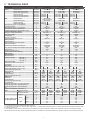 4
4
-
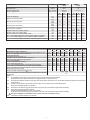 5
5
-
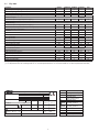 6
6
-
 7
7
-
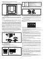 8
8
-
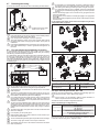 9
9
-
 10
10
-
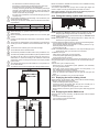 11
11
-
 12
12
-
 13
13
-
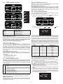 14
14
-
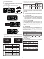 15
15
-
 16
16
-
 17
17
-
 18
18
-
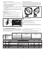 19
19
-
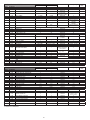 20
20
-
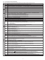 21
21
-
 22
22
-
 23
23
-
 24
24
-
 25
25
-
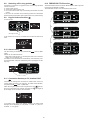 26
26
-
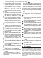 27
27
-
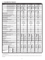 28
28
-
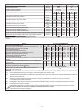 29
29
-
 30
30
-
 31
31
-
 32
32
-
 33
33
-
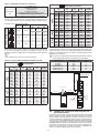 34
34
-
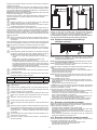 35
35
-
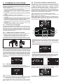 36
36
-
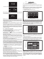 37
37
-
 38
38
-
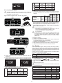 39
39
-
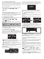 40
40
-
 41
41
-
 42
42
-
 43
43
-
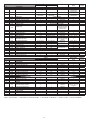 44
44
-
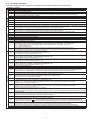 45
45
-
 46
46
-
 47
47
-
 48
48
-
 49
49
-
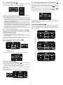 50
50
-
 51
51
-
 52
52
-
 53
53
-
 54
54
-
 55
55
-
 56
56
-
 57
57
-
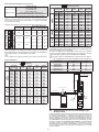 58
58
-
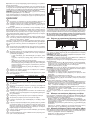 59
59
-
 60
60
-
 61
61
-
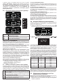 62
62
-
 63
63
-
 64
64
-
 65
65
-
 66
66
-
 67
67
-
 68
68
-
 69
69
-
 70
70
-
 71
71
-
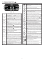 72
72
-
 73
73
-
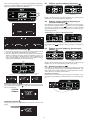 74
74
-
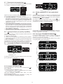 75
75
-
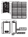 76
76
-
 77
77
-
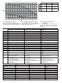 78
78
-
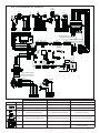 79
79
-
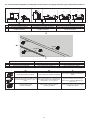 80
80
-
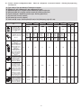 81
81
-
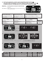 82
82
-
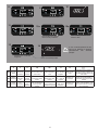 83
83
-
 84
84


