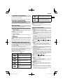
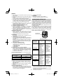
Hikoki CG36DB(L) Manual de utilizare
- Categorie
- Unelte electrice
- Tip
- Manual de utilizare
Acest manual este potrivit și pentru

CG 36DB • CG 36DB(L)
CG36DB
CG36DB(L)
en
de
fr
it
nl
es
pt
sv
da
no
fi
el
pl
hu
cs
tr
ro
sl
sk
bg
sr
hr
Handling instructions
Bedienungsanleitung
Mode d’emploi
Istruzioni per l’uso
Gebruiksaanwijzing
Instrucciones de manejo
Instruções de uso
Bruksanvisning
Brugsanvisning
Bruksanvisning
Käyttöohjeet
Οδηγίες χειρισμού
Instrukcja obsługi
Kezelési utasítás
Návod k obsluze
Kullanım talimatları
Instrucţiuni de utilizare
Navodila za rokovanje
Pokyny na manipuláciu
Инструкция за експлоатация
Uputstvo za rukovanje
Upute za rukovanje
en
de
fr
it
nl
es
pt
sv
da
no
fi
el
pl
hu
cs
tr
ro
sl
sk
bg
sr
hr

2
1
CG36DB
CG36DB(L)
B
K
A
E
F
G
D
D
C
C
I
L
M
K
J
E
F
G
B
A
H
23
45

3
67
89
10 11
a
b
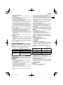
1.68 mm
2.38 mm

4
12 13 14
15 16 17
150 mm
18 19
100–150 mm

5
20 21
22
23
b
a

6
24
a-1
[CG36DB]
[CG36DB(L)]
a-2
25 26

7
English
Blade thrust may occur when the
spinning blade contacts a solid object in
the critical area. A dangerous reaction
may occur causing the entire unit and
operator to be thrust violently. This
reaction is called blade thrust. As a
result, the operator may lose control of
the unit which may cause serious or fatal
injury. Blade thrust is more likely to occur
in areas where it is diffi cult to see the
material to be cut.
Power switch
Switching on
Switching off
Mode switch
Eco mode
Normal mode
Power mode
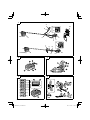
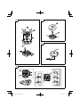
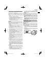
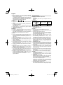
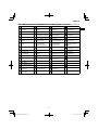
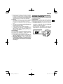
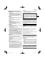
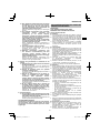
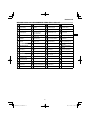
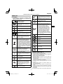
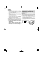
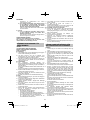
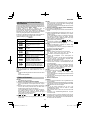
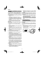
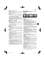
WHAT IS WHAT? (Fig. 1)
A: Lever: Trigger for activating the unit.
B: Lock lever: Lever that prevents the accidental operation
of the trigger.
C: Motor: Battery-driven motor.
D: Guard: Protects operator from fl ying debris.
E: Battery (sold separately): Power source to drive the unit.
F: Power switch: Switch for switching the units power unit's
power ON or OFF.
G: Mode switch: Switch for adjusting the speed of the
motor.
H: Handle right: Handle with lever located on the right side
of the unit.
I: Handle left: Handle located on the left side of the unit.
J: Handle fi xture: Secures the handles to the unit.
K: Hanger: Used for attaching a shoulder belt to the unit.
L: Loop handle
M: Shoulder belt: Harness with release mechanism.
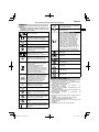
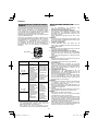
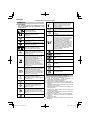
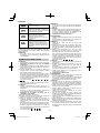
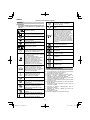
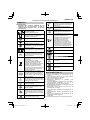
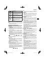
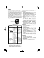
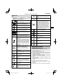
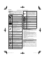
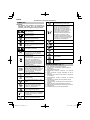
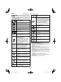
SYMBOLS
WARNING
The following show symbols used for the machine.
Be sure that you understand their meaning before
use.
CG36DB / CG36DB(L):
Cordless Grass Trimmer
To reduce the risk of injury, user must
read instruction manual.
Always wear eye protection.
Always wear hearing protection.
Do not use a power tool in the rain and
moisture or leave it outdoors when it is
raining.
Keep bystanders away.
Remove battery before adjusting or
cleaning and before leaving the machine
unattended for any period.
Only for EU countries
Do not dispose of electric tools together with
household waste material!
In observance of European Directive
2012/19/EU on waste electrical and electronic
equipment and its implementation in
accordance with national law, electric tools
that have reached the end of their life must
be collected separately and returned to an
environmentally compatible recycling facility.
It is important that you read, fully understand
and observe the following safety precautions
and warnings. Careless or improper use of the
unit may cause serious or fatal injury.
Read, understand and follow all
warnings and instructions in this manual
and on the unit.
Prohibited action
Always wear eye, head and ear
protectors when using this unit.
Keep all children, bystanders and
helpers 15 m away from the unit. If
anyone approaches you, stop the unit
and cutting attachment immediately.
Be careful of thrown objects.
Max
8,000 min-1
Shows maximum shaft speed. Do not
use the cutting attachment whose max
rpm is below the shaft rpm.
Gloves should be worn when necessary,
e.g., when assembling cutting
equipment.
Use anti-slip and sturdy footwear.
(Original instructions)

8
English
GENERAL POWER TOOL SAFETY
WARNINGS
WARNING
Read all safety warnings and all instructions.
Failure to follow the warnings and instructions may result in
electric shock, fi re and/or serious injury.
Save all warnings and instructions for future reference.
The term “power tool” in the warnings refers to your mains-
operated (corded) power tool or battery-operated (cordless)
power tool.
1) Work area safety
a) Keep work area clean and well lit.
Cluttered or dark areas invite accidents.
b) Do not operate power tools in explosive
atmospheres, such as in the presence of
fl ammable liquids, gases or dust.
Power tools create sparks which may ignite the dust
or fumes.
c) Keep children and bystanders away while
operating a power tool.
Distractions can cause you to lose control.
2) Electrical safety
a) Power tool plugs must match the outlet.
Never modify the plug in any way.
Do not use any adapter plugs with earthed
(grounded) power tools.
Unmodifi ed plugs and matching outlets will reduce
risk of electric shock.
b) Avoid body contact with earthed or grounded
surfaces, such as pipes, radiators, ranges and
refrigerators.
There is an increased risk of electric shock if your
body is earthed or grounded.
c) Do not expose power tools to rain or wet
conditions.
Water entering a power tool will increase the risk of
electric shock.
d) Do not abuse the cord. Never use the cord for
carrying, pulling or unplugging the power tool.
Keep cord away from heat, oil, sharp edges or
moving parts.
Damaged or entangled cords increase the risk of
electric shock.
e) When operating a power tool outdoors, use an
extension cord suitable for outdoor use.
Use of a cord suitable for outdoor use reduces the
risk of electric shock.
f) If operating a power tool in a damp location
is unavoidable, use a residual current device
(RCD) protected supply.
Use of an RCD reduces the risk of electric shock.
3) Personal safety
a) Stay alert, watch what you are doing and use
common sense when operating a power tool.
Do not use a power tool while you are tired
or under the infl uence of drugs, alcohol or
medication.
A moment of inattention while operating power tools
may result in serious personal injury.
b) Use personal protective equipment. Always
wear eye protection.
Protective equipment such as dust mask, non-skid
safety shoes, hard hat, or hearing protection used for
appropriate conditions will reduce personal injuries.
c) Prevent unintentional starting. Ensure the
switch is in the off position before connecting to
power source and/or battery pack, picking up or
carrying the tool.
Carrying power tools with your fi nger on the switch
or energising power tools that have the switch on
invites accidents.
d) Remove any adjusting key or wrench before
turning the power tool on.
A wrench or a key left attached to a rotating part of
the power tool may result in personal injury.
e) Do not overreach. Keep proper footing and
balance at all times.
This enables better control of the power tool in
unexpected situations.
f) Dress properly. Do not wear loose clothing or
jewellery. Keep your hair, clothing and gloves
away from moving parts.
Loose clothes, jewellery or long hair can be caught in
moving parts.
g) If devices are provided for the connection of
dust extraction and collection facilities, ensure
these are connected and properly used.
Use of dust collection can reduce dust related
hazards.
4) Power tool use and care
a) Do not force the power tool. Use the correct
power tool for your application.
The correct power tool will do the job better and safer
at the rate for which it was designed.
b) Do not use the power tool if the switch does not
turn it on and off .
Any power tool that cannot be controlled with the
switch is dangerous and must be repaired.
c) Disconnect the plug from the power source and/
or the battery pack from the power tool before
making any adjustments, changing accessories,
or storing power tools.
Such preventive safety measures reduce the risk of
starting the power tool accidentally.
d) Store idle power tools out of the reach of
children and do not allow persons unfamiliar
with the power tool or these instructions to
operate the power tool.
Power tools are dangerous in the hands of untrained
users.
e) Maintain power tools. Check for misalignment
or binding of moving parts, breakage of parts
and any other condition that may aff ect the
power toolʼs operation.
If damaged, have the power tool repaired before
use.
Many accidents are caused by poorly maintained
power tools.
f) Keep cutting tools sharp and clean.
Properly maintained cutting tools with sharp cutting
edges are less likely to bind and are easier to control.
g) Use the power tool, accessories and tool bits
etc. in accordance with these instructions,
taking into account the working conditions and
the work to be performed.
Use of the power tool for operations diff erent from
those intended could result in a hazardous situation.
5) Battery tool use and care
a) Recharge only with the charger specifi ed by the
manufacturer.
A charger that is suitable for one type of battery pack
may create a risk of fi re when used with another
battery pack.
b) Use power tools only with specifi cally
designated battery packs.
Use of any other battery packs may create a risk of
injury and fi re.

9
English
c) When battery pack is not in use, keep it away
from other metal objects, like paper clips, coins,
keys, nails, screws or other small metal objects,
that can make a connection from one terminal to
another.
Shorting the battery terminals together may cause
burns or a fi re.
d) Under abusive conditions, liquid may be ejected
from the battery; avoid contact. If contact
accidentally occurs, fl ush with water. If liquid
contacts eyes, additionally seek medical help.
Liquid ejected from the battery may cause irritation or
burns.
6) Service
a) Have your power tool serviced by a qualifi ed
repair person using only identical replacement
parts.
This will ensure that the safety of the power tool is
maintained.
PRECAUTION
Keep children and infi rm persons away.
When not in use, tools should be stored out of reach of
children and infi rm persons.
GRASS TRIMMER SAFETY
WARNINGS
IMPORTANT
READ CAREFULLY BEFORE USE
KEEP FOR FUTURE REFERENCE
Safe operation practices
● Training
a) Read the instructions carefully. Be familiar with the
controls and the correct use of the machine.
b) Never allow people unfamiliar with these instructions
or children to use the machine. Local regulations can
restrict the age of the operator.
c) Keep in mind that the operator or user is responsible for
accidents or hazards occurring to other people or their
property.
● Preparation
a) Before use check the supply and extension cord for
signs of damage or aging. If the cord becomes damaged
during use, disconnect the cord from the supply
immediately.
DO NOT TOUCH THE CORD BEFORE
DISCONNECTING THE SUPPLY.
Do not use the machine if the cord is damaged or worn.
b) Before use, always visually inspect the machine for
damaged, missing or misplaced guards or shields.
c) Never operate the machine while people, especially
children, or pets are nearby.
d) Never replace nylon head with metalic cutting means.
● Operation
a) Wear eye protection, stout shoes and long trousers at all
times while operating the machine.
b) Avoid using the machine in bad weather conditions
especially when there is a risk of lightning.
c) Use the machine only in daylight or good artifi cial light.
d) Never operate the machine with damaged guards or
shields or without guards or shields in place.
e) Switch on the motor only when the hands and feet are
away from the cutting means.
f) Always disconnect the machine from the power supply
(i.e. remove the plug from the mains or remove the
disabling device)
– whenever the machine is left user;
– before clearing a blockage;
– before checking, cleaning or working on the machine;
– after striking a foreign object to inspect the machine
for damage;
– if the machine starts to vivrate abnormally, for
immediately check.
g) Take care against injury to feet and hands from the
cutting means.
h) Always ensure that the ventilation openings are kept
clear of debris.
i) Never modify the unit/machine in any way. Do not use
your unit/machine for any job except that for which it is
intended.
● Maintenance, transport and storage
a) Disconnect the machine from the power supply (i.e.
remove the plug from the mains or remove the disabling
device) before carrying out maintenance or cleaning
work.
b) Use only the manufacturer’s recommended
replacement parts and accessories.
c) Inspect and maintain the machine regularly. Have the
machine repaired only by an authorized repairer.
d) When not in use, store the machine out of the reach of
children.
e) When transporting in a vehicle or storage, cover blade
with blade cover.
PRECAUTIONS FOR CORDLESS
GRASS TRIMMER
WARNING
1. Exercise patience in all work with the tool. And dress
properly to keep warm.
2. Plan all work ahead to prevent accidents.
3. Do not operate the tool at night or under bad weather
conditions when visibility is poor. And do not operate the
tool when it is raining or right after it has been raining.
Working on slippery ground could lead to an accident if
you lose your balance.
4. Inspect the nylon head before starting work.
Do not use the tool if the nylon head is cracked, scarred
or bent.
Make sure the nylon head is properly attached. A nylon
head that falls apart or comes loose during operation
could cause an accident.
5. Be sure to attach the guard before starting work.
Operating the tool without this parts could lead to injury.
6. Be sure to attach the handle before starting work. Make
sure it is not loose but properly attached before starting
work. Hold the handle fi rmly during work and do not
swing the tool around, but use the correct posture and
maintain your balance.
Losing your balance during work could lead to an injury.
7. Take care when starting the motor.
Place the tool on level ground.
Do not operate the tool within 15 m of people or animals.
Make sure that the nylon head does not come into
contact with the ground or trees and plants.
A careless start could lead to injury.
8. Do not secure the lock lever.
Accidentally pulling back the lever could lead to
unexpected injury.
9. Before leaving the tool, press the power switch to turn it
off .
10. Operate the tool with care near electric cables, gas pipes
and similar installations.
11. Look out for and remove empty cans, wire, stones or
other obstacles before starting work. And do not work
near tree roots or rocks.
Working in such areas could damage the nylon head or
lead to injury.
12. Never touch the nylon head during operation.
Also make sure it does not come into contact with your
hair, clothes, etc.

10
English
13. In the following situations, turn off the motor and check
that the nylon head has stopped rotating.
To move to another work area.
To remove rubbish or grass that has become stuck in the
tool.
To remove from the work area obstacles or the rubbish,
grass and chips generated by trimming.
To lay down the tool.
Doing this with the nylon head still rotating could lead to
unexpected accidents.
14. Do not use the tool within 15 m of another person.
When you work with someone else, maintain a distance
of more than 15 m.
Flying chips could lead to unexpected accidents.
When working on unstable surfaces like slopes, make
sure that your co-worker is not exposed to any hazards.
Use whistles or other means for calling the attention of
your co-workers.
15. When grass and other objects become entangled in the
nylon head, turn off the motor and make sure the nylon
head has stopped rotating before removing them.
Removing objects from the nylon head when it is still
rotating will lead to injury.
Continuing operation when foreign matter is stuck in the
nylon head may lead to damage.
16. If the tool is operating poorly and produces strange noise
or vibrations, turn off the motor immediately and ask your
dealer to have it inspected and repaired.
Continued use under these conditions could lead to
injury or tool damage.
17. If you drop or bump the tool, inspect it carefully to check
there is no damage, cracks or deformation.
Using a tool that is damaged, cracked or deformed could
result in injury.
18. Secure the tool during vehicle transport to ensure that it
lies still.
Failure to heed this warning may result in an accident.
19. This product contains a strong permanent magnet in the
motor.
Observe the following precautions regarding adhering of
chips to the tool and the eff ect of the permanent magnet
on electronic devices.
20. Do not use the product if the tool or the battery terminals
(battery mount) are deformed.
Installing the battery could cause a short circuit that
could result in smoke emission or ignition.
21. Keep the tool’s terminals (battery mount) free of swarf
and dust.
○ Prior to use, make sure that swarf and dust have not
collected in the area of the terminals.
○ During use, try to avoid swarf or dust on the tool from
falling on the battery.
○ When suspending operation or after use, do not leave
the tool in an area where it may be exposed to falling
swarf or dust.
Doing so could cause a short circuit that could result in
smoke emission or ignition.
CAUTION
○ Do not place the tool on a workbench or work area where
metal chips are present.
The chips may adhere to the tool, resulting in injury or
malfunction.
○ If chips have adhered to the tool, do not touch it. Remove
the chips with a brush.
Failure to do so may result in injury.
○ If you use a pacemaker or other electronic medical
device, do not operate or approach the tool.
Operation of the electronic device may be aff ected.
○ Do not use the tool in the vicinity of precision devices
such as cell phones, magnetic cards or electronic
memory media.
Doing so may lead to misoperation, malfunction or loss
of data.
CAUTION
1. Do not turn on the nylon head for cutting objects other
than grass. Do not operate the tool in water puddles and
make sure that soil does not come into contact with the
nylon head.
2. The tool contains precision parts and should not be
dropped, exposed to strong impact or water.
The tool could be damaged or malfunction.
3. When the tool is to be stored after use or be transported,
remove the nylon head.
4. Do not expose the tool to insecticide and other
chemicals.
Such chemicals could cause cracking and other
damage.
5. Replace warning labels with new labels when they
become diffi cult to recognize or illegible and when they
start to peel.
Ask your dealer to provide the warning labels.
6. Do not touch the motor immediately after use since it
may be very hot.
PRECAUTIONS FOR BATTERY AND
CHARGER (sold separately)
1. Always charge the battery at an ambient temperature of
-10–40°C. A temperature of less than -10°C will result in
over charging which is dangerous. The battery cannot be
charged at a temperature greater than 40°C.
The most suitable temperature for charging is that of
20–25°C.
2. Do not use the charger continuously.
When one charging is completed, leave the charger for
about 15 minutes before the next charging of battery.
3. Do not allow foreign matter to enter the hole for
connecting the rechargeable battery.
4. Never disassemble the rechargeable battery or charger.
5. Never short-circuit the rechargeable battery.
Short-circuiting the battery will cause a great electric
current and overheat. It results in burn or damage to the
battery.
6. Do not dispose of the battery in fi re.
If the battery is burnt, it may explode.
7. Using an exhausted battery will damage the charger.
8. Bring the battery to the shop from which it was purchased
as soon as the post-charging battery life becomes too
short for practical use. Do not dispose of the exhausted
battery.
9. Do not insert objects into the air ventilation slots of the
charger.
Inserting metal objects or fl ammable into the charger air
ventilation slots will result in an electrical shock hazard or
damage to the charger.

11
English
CAUTION ON LITHIUM-ION BATTERY
To extend the lifetime, the lithium-ion battery equips with the
protection function to stop the output.
In the cases of 1 to 3 described below, when using this
product, even if you are pulling the switch, the motor may
stop. This is not the trouble but the result of protection
function.
1. When the battery power remaining runs out, the motor
stops.
In such case, charge it up immediately.
2. If the tool is overloaded, the motor may stop. In this
case, release the switch of tool and eliminate causes of
overloading. After that, you can use it again.
3. If the battery is overheated under overload work, the
battery power may stop.
In this case, stop using the battery and let the battery
cool. After that, you can use it again.
Furthermore, please heed the following warning and caution.
WARNING
In order to prevent any battery leakage, heat generation,
smoke emission, explosion and ignition beforehand, please
be sure to heed the following precautions.
1. Make sure that swarf and dust do not collect on the
battery.
○ During work make sure that swarf and dust do not fall on
the battery.
○ Make sure that any swarf and dust falling on the power
tool during work do not collect on the battery.
○ Do not store an unused battery in a location exposed to
swarf and dust.
○ Before storing a battery, remove any swarf and dust that
may adhere to it and do not store it together with metal
parts (screws, nails, etc.).
2. Do not pierce battery with a sharp object such as a
nail, strike with a hammer, step on, throw or subject the
battery to severe physical shock.
3. Do not use an apparently damaged or deformed battery.
4. Do not use the battery in reverse polarity.
5. Do not connect directly to an electrical outlets or car
cigarette lighter sockets.
6. Do not use the battery for a purpose other than those
specifi ed.
7. If the battery charging fails to complete even when a
specifi ed recharging time has elapsed, immediately stop
further recharging.
8. Do not put or subject the battery to high temperatures or
high pressure such as into a microwave oven, dryer, or
high pressure container.
9. Keep away from fi re immediately when leakage or foul
odor are detected.
10. Do not use in a location where strong static electricity
generates.
11. If there is battery leakage, foul odor, heat generated,
discolored or deformed, or in any way appears abnormal
during use, recharging or storage, immediately remove it
from the equipment or battery charger, and stop use.
12. Do not immerse the battery or allow any fl uids to fl ow
inside. Conductive liquid ingress, such as water, can
cause damage resulting in fi re or explosion. Store your
battery in a cool, dry place, away from combustible and
fl ammable items. Corrosive gas atmospheres must be
avoided.
CAUTION
1. If liquid leaking from the battery gets into your eyes,
do not rub your eyes and wash them well with fresh
clean water such as tap water and contact a doctor
immediately.
If left untreated, the liquid may cause eye-problems.
2. If liquid leaks onto your skin or clothes, wash well with
clean water such as tap water immediately.
There is a possibility that this can cause skin irritation.
3. If you fi nd rust, foul odor, overheating, discolor,
deformation, and/or other irregularities when using the
battery for the fi rst time, do not use and return it to your
supplier or vendor.
WARNING
If an electrically conductive foreign object enters the
terminals of the lithium ion battery, a short-circuit may occur
resulting in the risk of fi re. Please observe the following
matters when storing the battery.
○ Do not place electrically conductive cuttings, nails,
steel wire, copper wire or other wire in the storage
case.
○ Either install the battery in the power tool or store
by securely pressing into the battery cover until the
ventilation holes are concealed to prevent short-
circuits (See Fig. 2).
REGARDING LITHIUM-ION BATTERY
TRANSPORTATION
When transporting a lithium-ion battery, please observe the
following precautions.
WARNING
Notify the transporting company that a package contains a
lithium-ion battery, inform the company of its power output
and follow the instructions of the transportation company
when arranging transport.
○ Lithium-ion batteries that exceed a power output of
100 Wh are considered to be in the freight classifi cation
of Dangerous Goods and will require special application
procedures.
○ For transportation abroad, you must comply with
international law and the rules and regulations of the
destination country.
Wh
Power Output
2 to 3 digit number

12
English
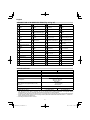
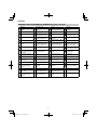
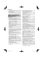
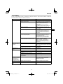
DESCRIPTION OF NUMBERED ITEMS (Fig. 2–Fig. 26)
Battery Handle right Button Groove
Latch Lever Wear limit mark
(2 marks) Fold back the middle
part
Battery cover Handle left Cutter holder Hook on the reel
Terminals Handle fi xture
(bike handlebars type) Hex. bar wrench 4 mm Direction to wind nylon
cord
Ventilation holes M5 × 25 hex. Socket
bolts 25 mm diameter boss Eyelet line guide
Push Guard Threaded fastener of
the gear case While holding the reel
Insert M6 × 25 hex. Socket
button bolts Nylon head tightening
direction (left rotation) String the line through
the eyelet line guide
Pull out Cover bracket Nylon line Locking holes of cover
(2 holes)
Battery level indicator
switch Gear case Tap Tabs of case (2 tabs)
Battery level indicator
lamp Knife Extends in 30 mm
increments Power switch
Main pipe Shoulder belt Tap/release Power lamp
Housing side Quick-release belt Appropriate length
90–110 mm Mode switch
Loop handle Hanger Cover Mode Indicator lamp
Handle fi xture
(loop handle type) Bracket Case Lock lever
M6 × 43 bolts Hook Hook Grip
M6 nuts Quick-release bracket Press tabs (2 areas)
Handle location label Nylon head Reel
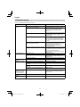
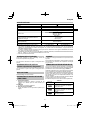
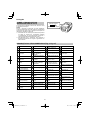
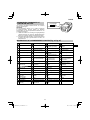
SPECIFICATIONS
Model CG36DB CG36DB(L)
Voltage 36 V
Pole type Straight type
Cutting capacity diameter 310 mm
Rotation direction Counterclockwise as seen from above
No-load speed 6500 min-1 (Power)
5500 min-1 (Normal)
4000 min-1 (Eco)
Operating time under no load*
(When supplied rechargeable battery is fully
charged)
BSL36B18
39 min (Power)
70 min (Normal)
122 min (Eco)
Battery available for this tool** (sold separately) Multi volt battery
Weight (with nylon head, rechargeable battery,
shoulder belt and guard)*** 4.8 kg (BSL36A18)
5.1 kg (BSL36B18) 4.6 kg (BSL36A18)
4.9 kg (BSL36B18)
* The data in the above table is provided only as an example. Since ambient temperature, rechargeable battery
characteristics, etc. can vary widely the above should only be used as a rough guideline.
Conditions: Outer diameter of nylon head 310 mm, mode switch set to Power, Normal or Eco. (lever left ON all the time)
** AC/DC Adapter (ET36A) cannot be used. Existing batteries (BSL3660/3626X/3626/3625/3620, BSL18.... and BSL14....
series) cannot be used with this tool.
*** According to EPTA-Procedure 01/2014

13
English
STANDARD ACCESSORIES
In addition to the main unit (1 unit), the package contains the
accessories listed on page 289.
Standard accessories are subject to change without notice.
OPTIONAL ACCESSORIES
(sold separately) (Page 290)
Optional accessories are subject to change without notice.
APPLICATIONS
Trimming, scaling and mowing of weed.
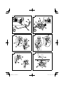
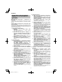
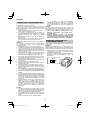
BATTERY REMOVAL/INSTALLATION
1. Battery removal
Hold the housing tightly and push the battery latches to
remove the battery (see Fig. 3).
CAUTION
Never short-circuit the battery.
2. Battery installation
Insert the battery while observing its polarities (see
Fig. 3).
CHARGING
Battery and battery charger are not included with this
product.
For rechargeable batteries, please charge in according to
the handling instructions of the charger which you are using.
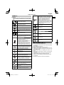
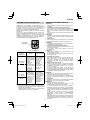
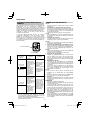
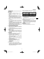
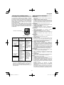
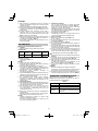
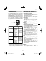
REMAINING BATTERY INDICATOR
You can check the battery’s remaining capacity by pressing
the remaining battery indicator switch to light the indicator
lamp. (Fig. 4, Table 1)
The indicator will shut off approximately 3 seconds after the
remaining battery indicator switch is pressed.
It is best to use the remaining battery indicator as a
guide since there are slight diff erences such as ambient
temperature and the condition of the battery.
Also, the remaining battery indicator may vary from those
equipped to a tool or charger.
(Battery is not included, sold separately)
Table 1
State of lamp Battery Remaining Power
Lights ;
The battery remaining power is over
75%
Lights ;
The battery remaining power is
50%–75%.
Lights ;
The battery remaining power is
25%–50%.
Lights ;
The battery remaining power is less
than 25%
Blinks ;
The battery remaining power is nearly
empty. Recharge the battery soonest
possible.
Blinks ;
Output suspended due to high
temperature. Remove the battery from
the tool and allow it to fully cool down.
Blinks ;
Output suspended due to failure or
malfunction. The problem may be the
battery so please contact your dealer.
As the remaining battery indicator shows somewhat
diff erently depending on ambient temperature and battery
characteristics, read it as a reference.
NOTE
Do not give a strong shock to the switch panel or break it.
It may lead to a trouble.
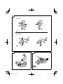
PRIOR TO OPERATION
CAUTION
Pull out battery before doing any assembly.
1. Installing the bike handlebars (Fig. 6) (CG36DB
only)
(1) Using the 4 mm hex wrench that is included, remove
the four bolts that have been temporarily secured to the
handle fi xture.
(2) Attach the handle right that has the lever and the handle
left, and then carefully secure the handle fi xture using
the four bolts.
To ensure the parts are attached securely, tighten the
bolts at least twice (repeating the following sequence).
Gradually increase the tightening torque each time to
ensure the bolts are tightened uniformly.
With four bolts: → → → → → → → ····
NOTE
Secure the handle left and handle right in a location that
provides a good grip.
CAUTION
Install the handle left and handle right properly and
securely as instructed in the handling instructions.
If not attached properly or securely, it may come off and
cause injury.
2. Installing the loop handle (Fig. 5) (CG36DB(L) only)
(1) Remove the M6 × 43 bolts (2 pcs.).
(2) Install the loop handle on the main pipe so that it leans
against the housing.
(3) Place the handle fi xture at the lower end of the main pipe
and secure it fi rmly using M6 × 43 bolts (2 pcs.) and M6
nuts (2 pcs.).
To ensure the parts are attached securely, tighten the
bolts at least twice (repeating the following sequence).
Gradually increase the tightening torque each time to
ensure the bolts are tightened uniformly.
With two bolts: → → → ····
NOTE
If your unit has handle location label on main pipe, follow
the illustration. (Fig. 5)
CAUTION
Install the loop handle properly and securely as
instructed in the handling instructions.
If not attached properly or securely, it may come off and
cause injury.
3. Installing guard (Fig. 7)
WARNING
Be sure to install the guard in its designated location.
Failure to heed this warning may result in injury from
fl ying stones.
NOTE
Use the supplied hex. bar wrench 4 mm for installation.
(1) Align the two holes in the cover bracket and the guard
and insert two M6 × 25 hex. socket button bolts. (The
cover bracket is installed in the gear case.)

14
English
(2) Use the supplied hex. bar wrench 4 mm to alternately
tighten the two M6 × 25 hex. socket button bolts until
they are properly tightened.
To ensure the parts are attached securely, tighten the
bolts at least twice (repeating the following sequence).
Gradually increase the tightening torque each time to
ensure the bolts are tightened uniformly.
With two bolts: → → → ····
CAUTION
○ Take care to avoid cutting yourself on the knife inside the
guard.
○ Install the guard properly and securely as instructed in
the handling instructions.
If not attached properly or securely, they may come off
and cause injury.
○ Check before use to confi rm that the guard is neither
damaged nor deformed.
4. Installing the shoulder belt
WARNING
○ Be sure to attach the shoulder belt so that the grass
trimmer can be carried correctly.
○ If you get the feeling the tool is not operating normally,
turn off the motor immediately, remove the quick-release
bracket of the shoulder belt and remove the tool.
CAUTION
○ If you do not support the tool when you pull the quick-
release belt, it may fall causing injury or damage.
Hold the main pipe with one hand while you pull with the
other hand.
○ Make sure the quick-release function operates normally
before you start working.
○ Before attaching, check to confi rm that the belt is not cut,
frayed, or damaged.
○ Check to confi rm that the hook and hanger are neither
deformed nor damaged.
○ Once attached, press down on the main unit to confi rm
that the hook does not detach easily and that the
shoulder belt is not loose.
○ Check to confi rm that the quick release function operates
as it should.
(1) Place the shoulder belt on the shoulder as shown in
Fig. 8 and engage it with the hanger on the tool. Adjust
the shoulder belt to suitable length.
(2) To remove the tool from the shoulder belt, support the
tool by holding the main pipe with one hand and use
the other hand to pull the quick-release belt as shown in
Fig. 9 to free it from the bracket.
(3) To strap on the tool, insert the bracket in the hook and
insert the quick-release bracket over the hook and into
the wide opening of the bracket. (Fig. 10)
Gently pull the shoulder belt to make sure that it is
properly attached.
NYLON HEAD
Installation of semi-auto nylon head
1. Function
Automatically feeds more nylon cutting line when it is
tapped.
Specifi cations
Code No. Type of
attaching
screw Direction of rotation Size of
attaching
screw
335234 Female
screw Counterclockwise M10×
P1.25-LH
Applicable nylon cord
Cord diameter: Fig. 11-a
Length: 4 m
CAUTION
○ The case must be securely attached to the cover.
○ Check the cover, case and other components for cracks
or other damage.
○ Check the case and button for wear.
If the wear limit mark on the case is no longer visible or
there is a hole in the bottom of the button, change the
new parts immediately. (Fig. 11-b)
○ The nylon head must be securely mounted to the
threaded fastener of the gear case.
○ For outstanding performance and reliability, always
use HiKOKI nylon cutting line. Never use wire or other
materials that could become a dangerous projectile.
○ If the nylon head does not feed cutting line properly,
check that the nylon line and all components are
properly installed. Contact your HiKOKI dealer if you
need assistance.
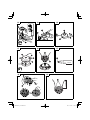
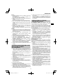
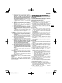
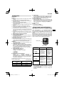
2. Installation (Fig. 12)
(1) Insert into the gear case so that the 25 mm diameter boss
on the cutter holder engages with the nylon head. Make
sure the protrusions and indentations on the spindle and
hole engage.
(2) Lock the spindle in place to keep it from rotating when
mounting the nylon head. To do so, insert the 4 mm hex
bar wrench into the gear case hole and one of the four
cutter holder holes.
(3) Screw the nylon head directly to the threaded fastener of
the gear case.
The mounting nut of nylon head is left-hand-threaded.
Turn clockwise to loosen/ counterclockwise to tighten.
CAUTION
Install the nylon head properly and securely as instructed
in the handling instructions.
If not attached properly or securely, it may come off and
cause injury.
3. Adjustment of line length
Rotate and tap the nylon head on the ground. Nylon line
is drawn out abt, 30 mm by one tapping. (Fig. 13)
Also, you can extend nylon line with hands. This time the
motor must be completely stopped.
Confi rm the line extends in 30 mm increments by
“tapping” and “releasing” the bottom button while pulling
the line ends of the nylon head. (Fig. 14)
○ Appropriate Length of Nylon Line
The appropriate length of the line when the tool is in use
is 90–110 mm. Extend the line to the appropriate length.

15
English
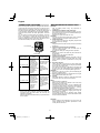
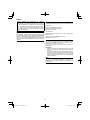
4. Nylon line replacement
(1) Prepare 4 m of genuine nylon line in Fig. 11-a. (Code
No. 335235)
(2) Press the opposing tabs, and then remove the cover
from the case. (Fig. 15)
(3) Remove the reel from the case. (Fig. 16)
○ If there is nylon line remaining, hook the line in the
grooves, and then remove the reel.
○ If the nylon line does not extend when there is enough
nylon line remaining, or when replacing the nylon line,
wind the nylon line using the following procedure.
(4) Release about 150 mm of the nylon cord from both ends,
fold the middle part and attach to the hook on the reel.
Next, wind the cord on the reel in the direction shown by
the arrow, being careful not to crisscross it (Fig. 17, 18).
NOTE
Do not cross the nylon line when securing the line in the
groove. (Fig. 18)
(5) Leave about 100 mm–150 mm nylon cord unwound,
hook and secure the line in the groove. (Fig. 19)
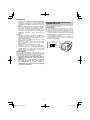
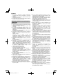
(6) Align the position of the stopper and eyelet line guide,
and then insert the button through the case.
Release the line from the stopper while holding the reel
lightly, and then string the line through the eyelet line
guide. (Fig. 20)
(7) Press and snap the tabs of the case in the locking holes
of the cover. (Fig. 21)
WARNING
Check to make sure the tabs are fi rmly snapped into the
locking holes.
Operating the tool while the parts are not fi rmly snapped
together may results in accidents or injury from fl ying
part.
(8) Pull the line taught so there is no slack, and then cut
the line to an extended length of 90 mm–110 mm with
scissors. (Fig. 22)
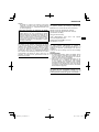
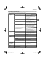
ABOUT POWER LAMP
The power lamp indicates various statuses for the tool.
(Fig. 23)
Table 2 shows the various statuses indicated by the power
lamp. (see page 16, “OPERATIONAL CAUTIONS”)
Table 2
State of lamp Status of Tool
Off Power OFF
Red Power ON
Blinking red The lever is being pressed while
the overload protection circuit of
the tool is operating.
OPERATION
Trimming grass
WARNING
○ Do not operate the tool at night or under bad weather
conditions when visibility is poor.
○ Do not operate the tool when it is raining or right after it
has been raining.
○ Wear proper footwear to prevent slipping that could
cause you to lose your balance and fall.
○ Do not use the tool on steep slopes.
When trimming grass on slopes that are not so steep,
trim by moving towards the ridge.
○ Take care not to move the nylon head too close to your
feet.
○ Do not raise the nylon head above your knee during
cutting.
○ Do not use the tool where the nylon head may come into
contact with stones, tree and other obstacles.
○ A nylon head can injure while it continues to spin after
the motor is stopped. When the unit is turned off , make
sure the nylon head has stopped before the unit is set
down.
○ Do not use the tool within 15 m of another person. When
you work with someone else, maintain a distance of
more than 15 m.
1. Insert the battery while observing its polarities.
2. Turn on the tool. (Fig. 23-a)
○ Press the power switch on the housing, the power goes
on and the power lamp on the housing lights red.
○ Pressing the power switch a second time turns the
power off and the red lamp on the housing goes off .
[Auto power off ]
When the power is turned on but the lever is not used for
one minute, the tool is automatically turned off . To turn
the tool on again, press the power switch a second time.
WARNING
Never leave the tool with the power on. This could result
in an accident.
3. Lever operation and brake (Fig. 24)
To start rotation of the nylon head, with the power turned
on, pull the lever while pressing the lock lever.
When you release the lever, the brake engages in
1–3 seconds, stopping rotation of the nylon head.
Make sure that the brake operates normally before using
the tool.
4. Mode switch (Fig. 23-b)
The tool is equipped with three modes:
“Power Mode” “Normal Mode” “Eco Mode”.
(1) Power Mode
(2) Normal Mode
(3) Eco Mode
● Work Capacity on a Full Charge
The following is a rough estimate of the amount of work
provided by the grass trimmer when on a full charge.
(The amount of work varies somewhat due to ambient
temperature and characteristics of the battery)
Time in continuous operation when switch fully depressed
in each mode (Under no load)
Battery
Mode BSL36B18
Power 39 min
Normal 70 min
Eco 122 min
5. Trimming grass
○ Grip the handle, press the lock lever and pull the lever to
start cutting head rotation. (Fig. 24 a-1, a-2)
○ Release the lever when you fi nish trimming and stop the
motor.
○ Take a posture that makes it easy to move.
[Grass trimming techniques]
Do not swing the pipe, but use the hips to move the
nylon head horizontally from left to right in an arc while
going forward and use the right side of the nylon head for
cutting grass. (Fig. 25)
6. Carrying the tool
CAUTION
○ Remove the storage battery. (Fig. 3)
○ Carry the tool holding with hands.

16
English
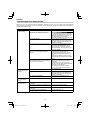
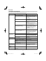
OPERATIONAL CAUTIONS
This tool incorporates a function to safeguard the electronic
components that control the main unit. If an overload occurs
during mowing—for example, if the nylon head locks up or
becomes clogged with vegetation—the function will activate
to stop the motor. If this happens, the power lamp will fl ash.
Check the lamp status and take appropriate corrective
action.
You can resume use after taking the following corrective
action. Take steps to reduce the load imposed on the
motor—for example, by reducing the cutting depth. Before
clearing vegetation from the nylon head, turn off the power
and remove the battery from the tool main unit.
Power switch
Power lamp
Power lamp
fl ashing status Cause Corrective action
0.5 s on/0.5 s off
(slow fl ashing)
The internal
temperature
exceeded the
preset limit. The
tool has stopped.
(The motor turns
off . The power
will shut down
automatically after
one minute.)
[Temperature
protection
function]
Turn off the power
and wait for the
device to cool.
You can
resume use
once the device
temperature has
fallen.
0.1 s on/0.1 s off
(rapid fl ashing)
The tool
attachment load
exceeded the
preset limit. The
tool has stopped.
(The motor
turns off and the
lamp fl ashes for
10 seconds.)
[Overload
protection
function]
Turn off the power
and remove the
battery. Resolve
the cause of the
overload.
You can resume
use after resolving
the overload
cause.
NOTE
If the power lamp continues to fl ash even after the
corrective action has been taken, the tool may be
damaged or defective.
Please contact the retail outlet where you purchased the
tool for repairs.
MAINTENANCE AND INSPECTION
CAUTION
Pull out battery before doing any inspection or
maintenance.
1. Checking the condition of the nylon head
The nylon head should be checked regularly. If worn or
broken nylon head can slip or decrease the effi ciency of
the motor and burn it out.
Replace worn nylon head with new ones.
CAUTION
If you use a nylon head of which point is worn or broken,
it will be dangerous. So replace it with a new one.
2. Check the Screws
Loose screws are dangerous. Regularly inspect them
and make sure they are tight.
CAUTION
Using this power tool with loosened screws is extremely
dangerous.
3. Inspection of terminals (tool and battery)
Check to make sure that swarf and dust have not
collected on the terminals.
On occasion check prior, during and after operation.
CAUTION
Remove any swarf or dust which may have collected on
the terminals.
Failure to do so may result in malfunction.
4. Cleaning of the outside
When the grass trimmer is stained, wipe with a soft dry
cloth or a cloth moistened with soapy water. Do not use
chloric solvents, gasoline or paint thinner, as they melt
plastics.
5. Gear case (Fig. 26)
Check gear case or angle gear for grease level about
every 50 hours of operation by removing the grease fi ller
plug on the side of gear case.
If no grease can be seen on the fl anks of the gears, fi ll
the gear case with quality lithium based multipurpose
grease up to 3/4. Do not completely fi ll the gear case.
CAUTION
○ Make sure to remove any dirt or grit when attaching the
plug to its original position.
○ Before attempting inspection or maintenance of the gear
case, make sure the case has cooled.
6. Storage
Store grass trimmer in a place in which the temperature
is less than 40°C and out of reach of children.
NOTE
Storing Lithium-ion Batteries
Make sure the lithium-ion batteries have been fully
charged before storing them.
Prolonged storage (3 months or more) of batteries with
a low charge may result in performance deterioration,
signifi cantly reducing battery usage time or rendering
the batteries incapable of holding a charge.
However, signifi cantly reduced battery usage time may
be recovered by repeatedly charging and using the
batteries two to fi ve times.
If the battery usage time is extremely short despite
repeated charging and use, consider the batteries dead
and purchase new batteries.
CAUTION
In the operation and maintenance of power tools, the
safety regulations and standards prescribed in each
country must be observed.

17
English
Important notice on the batteries for the HiKOKI
cordless power tools
Please always use one of our designated genuine
batteries. We cannot guarantee the safety and
performance of our cordless power tool when used with
batteries other than these designated by us, or when
the battery is disassembled and modifi ed (such as
disassembly and replacement of cells or other internal
parts).
GUARANTEE
We guarantee HiKOKI Power Tools in accordance with
statutory/country specifi c regulation. This guarantee does
not cover defects or damage due to misuse, abuse, or
normal wear and tear. In case of complaint, please send
the Power Tool, undismantled, with the GUARANTEE
CERTIFICATE found at the end of this Handling instruction,
to a HiKOKI Authorized Service Center.
Information concerning airborne noise and vibration
The measured values were determined according to
EN50636-2-91 and declared in accordance with ISO 4871.
Measured A-weighted sound power level: 95 dB (A).
Measured A-weighted sound pressure level: 82 dB (A).
Uncertainty K: 2.5 dB (A).
Wear hearing protection.
Vibration total values (triax vector sum) determined
according to EN50636-2-91.
Vibration emission value ah, w = 5.6 m/s2
Uncertainty K = 1.5 m/s2
The declared vibration total value has been measured in
accordance with a standard test method and may be used
for comparing one tool with another.
It may also be used in a preliminary assessment of exposure.
WARNING
○ The vibration emission during actual use of the power
tool can diff er from the declared total value depending
on the ways in which the tool is used.
○
Identify safety measures to protect the operator that are
based on an estimation of exposure in the actual conditions
of use (taking account of all parts of the operating cycle
such as the times when the tool is switched off and when it
is running idle in addition to the trigger time).
NOTE
Due to HiKOKI’s continuing program of research and
development, the specifi cations herein are subject to
change without prior notice.

18
English
TROUBLESHOOTING
Use the inspections in the table below if the tool does not operate normally. If this does not remedy the problem, consult your
dealer or the HiKOKI Authorized Service Center.
Symptom Possible cause Remedy
The tool does not
function. The battery is dead. Recharge the battery.
The battery is not fully inserted. Pull out the battery and remove any debris
from the battery compartment.
Use cotton swabs or similar materials
to remove dirt or water from the battery
terminals.
Insert the battery fi rmly until it clicks into place.
The battery is overheated. Stop using the tool. Remove the battery and
allow the battery to cool in a shaded, well-
ventilated area.
The power is not on. Press the power switch on the housing.
The tool features an auto power off function
that turns the power off automatically after
one minute if the operator does not operate
the lever.
The operator attempted to pull the lever
without pressing the lock lever. The tool will not allow operation of the lever
unless the operator presses the lock lever to
release the safety lock mechanism.
Grasp the handle and press the lock lever
while pulling the lever.
Excessive vegetation entangled in the guard
and nylon head overloaded the motor. If overloaded, the motor may cut out to protect
the tool and battery.
Turn off the power, remove the battery, and
clear the cause of the overload.
The tool can be used again after turning the
power back on.
The tool starts, then
stops soon. The battery is low. Recharge the battery.
The battery is overheated. Stop using the tool. Remove the battery and
allow the battery to cool in a shaded, well-
ventilated area.
The tool is overloaded. Reduce the cutting depth to reduce the load.
The speed cannot be
changed. The battery is low. Recharge the battery.
Vibration is excessive. The nylon head is not correctly attached. Reattach the nylon head.
The nylon head is cracked, broken, or
deformed. Replace the nylon head.
The handle is not securely attached to the
main pipe. Attach securely.
The guard is not securely attached to the
main pipe. Attach securely.
The brake takes more
than three seconds to
take eff ect, even after
you release the lever.
There may be a problem with the product. Contact the store where you purchased
the tool or your nearest HiKOKI Authorized
Service Center.
The battery cannot be
attached. The battery is not the type specifi ed. Use only MULTI VOLT batteries.
The nylon head will not
turn.
The nylon head mount is not fi tted correctly. Reattach the nylon head mount.

19
Deutsch
(Übersetzung der Original-Gebrauchsanweisung)
SYMBOLE
WARNUNG
Die folgenden Symbole werden für diese Maschine
verwendet. Achten Sie darauf, diese vor der
Verwendung zu verstehen.
CG36DB / CG36DB(L):
Akku-Rasentrimmer
Der Anwender muss die
Bedienungsanleitung lesen, um das
Risiko einer Verletzung zu verringern.
Tragen Sie immer einen Augenschutz.
Stets Gehörschutz tragen.
Benutzen Sie das Elektrowerkzeug nicht
im Regen und bei Feuchtigkeit oder
lassen Sie es nicht im Freien liegen,
wenn es regnet.
Achten Sie darauf, dass keine
unbeteiligten Personen in der Nähe sind.
Entfernen Sie die Batterie vor dem
Einstellen und der Reinigung sowie
dann, wenn das Gerät unbeaufsichtigt
ist.
Nur für EU-Länder
Werfen Sie Elektrowerkzeuge nicht in
den Hausmüll!
Gemäss Europäischer Richtlinie
2012/19/EU über Elektro- und
Elektronik- Altgeräte und Umsetzung in
nationales Recht müssen verbrauchte
Elektrowerkzeuge getrennt gesammelt
und einer umweltgerechaten
Wiederververtung zugeführt werden.
Es ist wichtig, dass Sie sich mit den
nachfolgenden Vorsichtsmaßnahmen
und Warnungen vertraut machen und
diese befolgen. Unvorsichtige oder
unsachgemäße Handhabung des
Geräts kann schwere oder tödliche
Verletzungen zur Folge haben.
Lesen, verstehen und befolgen Sie alle
Warnungen und Anweisungen in dieser
Anleitung und am Gerät selbst.
Unzulässige Handlung
Bei Gebrauch des Geräts immer
Gesichts-, Kopf- und Gehörschutz
tragen.
Kinder und Zuschauer in einem Abstand
von 15 m vom Gerät halten. Stoppen Sie
das Gerät und die Schneideinheit sofort,
wenn sich Ihnen jemand nähert.
Auf hochgeschleuderte Gegenstände
achten.
Max
8,000 min-1
Zeigt die maximale Drehzahl der Welle
an. Verwenden Sie kein Schneidzubehör,
dessen Maximaldrehzahl unter diesem
Wert liegt.
Handschuhe sind dann zu tragen, wenn
dies notwendig ist, z.B. bei der Montage
der Schneidausrüstung.
Rutschfestes Schuhwerk tragen, das
guten Halt bietet.
Ein Messerstoß ist möglich, wenn das
rotierende Messer im kritischen Bereich
mit einem massiven Gegenstand in
Berührung kommt. In diesem Fall kann
es zu einer gefährlichen Reaktion
kommen, bei der das gesamte Gerät
und der Bediener einem heftigen Stoß
ausgesetzt werden. Diese Reaktion
wird als Messerstoß bezeichnet. Das
Resultat ist u.U., dass der Bediener
die Kontrolle über das Gerät verliert
und schwere oder lebensgefährliche
Verletzungen davonträgt. Messerstöße
sind in Arbeitsbereichen, wo das zu
schneidende Vegetationsmaterial nur
schwer einsehbar ist, wahrscheinlicher.
Netzschalter
Einschalten
Ausschalten
Modusschalter
Eco-Modus
Normal-Modus
Power-Modus
WAS IST WAS? (Abb. 1)
A: Hebel: Auslöser zum Aktivieren des Gerätes.
B: Verriegelungshebel: Hebel, der ein unbeabsichtigtes
Betätigen des Auslösers verhindert.
C: Motor: Akkubetriebener Motor.
D: Messerschutz: Schützt den Bediener vor
herumfl iegenden Trümmern.
E: Batterie (separat erhältlich): Energiequelle für den
Antrieb des Gerätes.
F: Netzschalter: Schalter zum Ein- und Ausschalten der
Stromversorgung des Geräts.
G: Modusschalter: Schalter zur Einstellung der
Motordrehzahl.
H: Griff rechts: Griff mit Hebel an der rechten Seite des
Gerätes.
I: Griff links: Griff an der rechten Seite des Gerätes.
J: Griff einbau: Sichert die Griff e am Gerät.
K: Hänger: Wird zur Befestigung eines Schulterriemens am
Gerät verwendet.
L: Bügelgriff
M: Schulterriemen: Gurt mit Lösemechanismus.

20
Deutsch
ALLGEMEINE
SICHERHEITSHINWEISE FÜR
ELEKTROGERÄTE
WARNUNG
Lesen Sie sämtliche Sicherheitshinweise und
Anweisungen durch.
Wenn die Warnungen und Anweisungen nicht befolgt
werden, kann es zu Stromschlag, Brand und/oder
ernsthaften Verletzungen kommen.
Bitte bewahren Sie alle Warnhinweise und
Anweisungen zum späteren Nachschlagen auf.
er Begriff „Elektrowerkzeug“ bezieht sich in den
Warnhinweisen auf Elektrowerkzeuge mit Netz-
(schnurgebunden) oder Akkubetrieb (schnurlos).
1) Sicherheit im Arbeitsbereich
a) Sorgen Sie für einen sauberen und gut
ausgeleuchteten Arbeitsbereich.
Zugestellte oder dunkle Bereiche ziehen Unfälle
förmlich an.
b) Verwenden Sie Elektrowerkzeuge niemals an
Orten, an denen Explosionsgefahr besteht – zum
Beispiel in der Nähe von leicht entfl ammbaren
Flüssigkeiten, Gasen oder Stäuben.
Bei der Arbeit mit Elektrowerkzeugen kann es zu
Funkenbildung kommen, wodurch sich Stäube oder
Dämpfe entzünden können.
c) Sorgen Sie bei der Arbeit mit Elektrowerkzeugen
dafür, dass sich keine Zuschauer (insbesondere
Kinder) in der Nähe befi nden.
Wenn Sie abgelenkt werden, können Sie die
Kontrolle über das Werkzeug verlieren.
2) Elektrische Sicherheit
a) Elektrowerkzeuge müssen mit passender
Stromversorgung betrieben werden.
Nehmen Sie niemals irgendwelche Änderungen
am Anschlussstecker vor.
Verwenden Sie bei Elektrowerkzeugen
mit Schutzkontakt (geerdet) niemals
Adapterstecker.
Stecker im Originalzustand und passende
Steckdosen reduzieren das Stromschlagrisiko.
b) Vermeiden Sie Körperkontakt mit geerdeten
Gegenständen wie Rohrleitungen, Heizungen,
Herden oder Kühlschränken.
Bei Körperkontakt mit geerdeten Gegenständen
besteht ein erhöhtes Stromschlagrisiko.
c) Setzen Sie Elektrowerkzeuge niemals Regen
oder sonstiger Feuchtigkeit aus.
Wenn Flüssigkeiten in ein Elektrowerkzeug
eindringen, erhöht sich das Stromschlagrisiko.
d) Verwenden Sie das Anschlusskabel
nicht missbräuchlich. Tragen Sie
das Elektrowerkzeug niemals an der
Anschlussschnur, ziehen Sie es nicht damit
heran und ziehen Sie den Stecker nicht an der
Anschlussschnur aus der Steckdose.
Halten Sie die Anschlussschnur von
Hitzequellen, Öl, scharfen Kanten und
beweglichen Teilen fern.
Beschädigte oder verdrehte Anschlussschnüre
erhöhen das Stromschlagrisiko.
e) Wenn Sie ein Elektrowerkzeug im Freien
benutzen, verwenden Sie ein für den
Außeneinsatz geeignetes Verlängerungskabel.
Ein für den Außeneinsatz geeignetes Kabel
vermindert das Stromschlagrisiko.
f) Falls sich der Betrieb des Elektrowerkzeuges
in feuchter Umgebung nicht vermeiden lässt,
verwenden Sie eine Stromversorgung mit
Fehlerstromschutzeinrichtung (Residual
Current Device, RCD).
Durch den Einsatz einer
Fehlerstromschutzeinrichtung wird das Risiko eines
elektrischen Schlages reduziert.
3) Persönliche Sicherheit
a) Bleiben Sie wachsam, achten Sie auf das, was
Sie tun, und setzen Sie Ihren Verstand ein, wenn
Sie mit Elektrowerkzeugen arbeiten.
Benutzen Sie keine Elektrowerkzeuge, wenn
Sie müde sind oder unter Einfl uss von Drogen,
Alkohol oder Medikamenten stehen.
Bei der Arbeit mit Elektrowerkzeugen können bereits
kurze Phasen der Unaufmerksamkeit zu schweren
Verletzungen führen.
b) Benutzen Sie eine persönliche
Schutzausrüstung. Tragen Sie immer einen
Augenschutz.
Schutzausrüstung wie Staubmaske, rutschsichere
Sicherheitsschuhe, Schutzhelm und Gehörschutz
senken das Verletzungsrisiko bei angemessenem
Einsatz.
c) Vermeiden Sie unbeabsichtigtes Einschalten.
Achten Sie darauf, dass sich der Schalter
in der Aus- (Off -) Position befi ndet, ehe Sie
das Gerät mit der Stromversorgung und/
oder Batteriestromversorgung verbinden, es
aufheben oder herumtragen.
Das Herumtragen von Elektrowerkzeugen mit
dem Finger am Schalter oder das Herstellen der
Stromversorgung bei betätigtem Schalter zieht
Unfälle regelrecht an.
d) Entfernen Sie sämtliche Einstellwerkzeuge
(Einstellschlüssel), ehe Sie das Elektrowerkzeug
einschalten.
Ein an einem beweglichen Teil des Elektrowerkzeugs
angebrachter Schlüssel kann zu Verletzungen
führen.
e) Sorgen Sie für einen festen Stand. Achten Sie
jederzeit darauf, sicher zu stehen und das
Gleichgewicht zu bewahren.
Dadurch haben Sie das Elektrowerkzeug in
unerwarteten Situationen besser im Griff .
f) Kleiden Sie sich richtig. Tragen Sie keine lose
Kleidung oder Schmuck. Halten Sie Haar,
Kleidung und Handschuhe von beweglichen
Teilen fern.
Lose Kleidung, Schmuck oder langes Haar kann von
beweglichen Teilen erfasst werden.
g) Wenn Anschlüsse für Staubabsaug- und -
sammelvorrichtungen vorhanden sind, sorgen
Sie dafür, dass diese richtig angeschlossen und
eingesetzt werden.
Durch Entfernen des Staubes können
staubbezogene Gefahren vermindert werden.
4) Einsatz und Pfl ege von Elektrowerkzeugen
a) Überanspruchen Sie Elektrowerkzeuge nicht.
Benutzen Sie das richtige Elektrowerkzeug für
Ihren Einsatzzweck.
Das richtige Elektrowerkzeug erledigt seine Arbeit bei
bestimmungsgemäßem Einsatz besser und sicherer.
b) Benutzen Sie das Elektrowerkzeug nicht, wenn
es sich nicht am Schalter ein- und ausschalten
lässt.
Jedes Elektrowerkzeug, das nicht mit dem Schalter
betätigt werden kann, stellt eine Gefahr dar und
muss repariert werden.
Pagina se încarcă...
Pagina se încarcă...
Pagina se încarcă...
Pagina se încarcă...
Pagina se încarcă...
Pagina se încarcă...
Pagina se încarcă...
Pagina se încarcă...
Pagina se încarcă...
Pagina se încarcă...
Pagina se încarcă...
Pagina se încarcă...
Pagina se încarcă...
Pagina se încarcă...
Pagina se încarcă...
Pagina se încarcă...
Pagina se încarcă...
Pagina se încarcă...
Pagina se încarcă...
Pagina se încarcă...
Pagina se încarcă...
Pagina se încarcă...
Pagina se încarcă...
Pagina se încarcă...
Pagina se încarcă...
Pagina se încarcă...
Pagina se încarcă...
Pagina se încarcă...
Pagina se încarcă...
Pagina se încarcă...
Pagina se încarcă...
Pagina se încarcă...
Pagina se încarcă...
Pagina se încarcă...
Pagina se încarcă...
Pagina se încarcă...
Pagina se încarcă...
Pagina se încarcă...
Pagina se încarcă...
Pagina se încarcă...
Pagina se încarcă...
Pagina se încarcă...
Pagina se încarcă...
Pagina se încarcă...
Pagina se încarcă...
Pagina se încarcă...
Pagina se încarcă...
Pagina se încarcă...
Pagina se încarcă...
Pagina se încarcă...
Pagina se încarcă...
Pagina se încarcă...
Pagina se încarcă...
Pagina se încarcă...
Pagina se încarcă...
Pagina se încarcă...
Pagina se încarcă...
Pagina se încarcă...
Pagina se încarcă...
Pagina se încarcă...
Pagina se încarcă...
Pagina se încarcă...
Pagina se încarcă...
Pagina se încarcă...
Pagina se încarcă...
Pagina se încarcă...
Pagina se încarcă...
Pagina se încarcă...
Pagina se încarcă...
Pagina se încarcă...
Pagina se încarcă...
Pagina se încarcă...
Pagina se încarcă...
Pagina se încarcă...
Pagina se încarcă...
Pagina se încarcă...
Pagina se încarcă...
Pagina se încarcă...
Pagina se încarcă...
Pagina se încarcă...
Pagina se încarcă...
Pagina se încarcă...
Pagina se încarcă...
Pagina se încarcă...
Pagina se încarcă...
Pagina se încarcă...
Pagina se încarcă...
Pagina se încarcă...
Pagina se încarcă...
Pagina se încarcă...
Pagina se încarcă...
Pagina se încarcă...
Pagina se încarcă...
Pagina se încarcă...
Pagina se încarcă...
Pagina se încarcă...
Pagina se încarcă...
Pagina se încarcă...
Pagina se încarcă...
Pagina se încarcă...
Pagina se încarcă...
Pagina se încarcă...
Pagina se încarcă...
Pagina se încarcă...
Pagina se încarcă...
Pagina se încarcă...
Pagina se încarcă...
Pagina se încarcă...
Pagina se încarcă...
Pagina se încarcă...
Pagina se încarcă...
Pagina se încarcă...
Pagina se încarcă...
Pagina se încarcă...
Pagina se încarcă...
Pagina se încarcă...
Pagina se încarcă...
Pagina se încarcă...
Pagina se încarcă...
Pagina se încarcă...
Pagina se încarcă...
Pagina se încarcă...
Pagina se încarcă...
Pagina se încarcă...
Pagina se încarcă...
Pagina se încarcă...
Pagina se încarcă...
Pagina se încarcă...
Pagina se încarcă...
Pagina se încarcă...
Pagina se încarcă...
Pagina se încarcă...
Pagina se încarcă...
Pagina se încarcă...
Pagina se încarcă...
Pagina se încarcă...
Pagina se încarcă...
Pagina se încarcă...
Pagina se încarcă...
Pagina se încarcă...
Pagina se încarcă...
Pagina se încarcă...
Pagina se încarcă...
Pagina se încarcă...
Pagina se încarcă...
Pagina se încarcă...
Pagina se încarcă...
Pagina se încarcă...
Pagina se încarcă...
Pagina se încarcă...
Pagina se încarcă...
Pagina se încarcă...
Pagina se încarcă...
Pagina se încarcă...
Pagina se încarcă...
Pagina se încarcă...
Pagina se încarcă...
Pagina se încarcă...
Pagina se încarcă...
Pagina se încarcă...
Pagina se încarcă...
Pagina se încarcă...
Pagina se încarcă...
Pagina se încarcă...
Pagina se încarcă...
Pagina se încarcă...
Pagina se încarcă...
Pagina se încarcă...
Pagina se încarcă...
Pagina se încarcă...
Pagina se încarcă...
Pagina se încarcă...
Pagina se încarcă...
Pagina se încarcă...
Pagina se încarcă...
Pagina se încarcă...
Pagina se încarcă...
Pagina se încarcă...
Pagina se încarcă...
Pagina se încarcă...
Pagina se încarcă...
Pagina se încarcă...
Pagina se încarcă...
Pagina se încarcă...
Pagina se încarcă...
Pagina se încarcă...
Pagina se încarcă...
Pagina se încarcă...
Pagina se încarcă...
Pagina se încarcă...
Pagina se încarcă...
Pagina se încarcă...
Pagina se încarcă...
Pagina se încarcă...
Pagina se încarcă...
Pagina se încarcă...
Pagina se încarcă...
Pagina se încarcă...
Pagina se încarcă...
Pagina se încarcă...
Pagina se încarcă...
Pagina se încarcă...
Pagina se încarcă...
Pagina se încarcă...
Pagina se încarcă...
Pagina se încarcă...
Pagina se încarcă...
Pagina se încarcă...
Pagina se încarcă...
Pagina se încarcă...
Pagina se încarcă...
Pagina se încarcă...
Pagina se încarcă...
Pagina se încarcă...
Pagina se încarcă...
Pagina se încarcă...
Pagina se încarcă...
Pagina se încarcă...
Pagina se încarcă...
Pagina se încarcă...
Pagina se încarcă...
Pagina se încarcă...
Pagina se încarcă...
Pagina se încarcă...
Pagina se încarcă...
Pagina se încarcă...
Pagina se încarcă...
Pagina se încarcă...
Pagina se încarcă...
Pagina se încarcă...
Pagina se încarcă...
Pagina se încarcă...
Pagina se încarcă...
Pagina se încarcă...
Pagina se încarcă...
Pagina se încarcă...
Pagina se încarcă...
Pagina se încarcă...
Pagina se încarcă...
Pagina se încarcă...
Pagina se încarcă...
Pagina se încarcă...
Pagina se încarcă...
Pagina se încarcă...
Pagina se încarcă...
Pagina se încarcă...
Pagina se încarcă...
Pagina se încarcă...
Pagina se încarcă...
Pagina se încarcă...
Pagina se încarcă...
Pagina se încarcă...
Pagina se încarcă...
Pagina se încarcă...
Pagina se încarcă...
Pagina se încarcă...
Pagina se încarcă...
Pagina se încarcă...
Pagina se încarcă...
Pagina se încarcă...
Pagina se încarcă...
Pagina se încarcă...
Pagina se încarcă...
Pagina se încarcă...
Pagina se încarcă...
Pagina se încarcă...
Pagina se încarcă...
Pagina se încarcă...
Pagina se încarcă...
Pagina se încarcă...
Pagina se încarcă...
Pagina se încarcă...
Pagina se încarcă...
Pagina se încarcă...
Pagina se încarcă...
Pagina se încarcă...
Pagina se încarcă...
Pagina se încarcă...
Pagina se încarcă...
Pagina se încarcă...
-
 1
1
-
 2
2
-
 3
3
-
 4
4
-
 5
5
-
 6
6
-
 7
7
-
 8
8
-
 9
9
-
 10
10
-
 11
11
-
 12
12
-
 13
13
-
 14
14
-
 15
15
-
 16
16
-
 17
17
-
 18
18
-
 19
19
-
 20
20
-
 21
21
-
 22
22
-
 23
23
-
 24
24
-
 25
25
-
 26
26
-
 27
27
-
 28
28
-
 29
29
-
 30
30
-
 31
31
-
 32
32
-
 33
33
-
 34
34
-
 35
35
-
 36
36
-
 37
37
-
 38
38
-
 39
39
-
 40
40
-
 41
41
-
 42
42
-
 43
43
-
 44
44
-
 45
45
-
 46
46
-
 47
47
-
 48
48
-
 49
49
-
 50
50
-
 51
51
-
 52
52
-
 53
53
-
 54
54
-
 55
55
-
 56
56
-
 57
57
-
 58
58
-
 59
59
-
 60
60
-
 61
61
-
 62
62
-
 63
63
-
 64
64
-
 65
65
-
 66
66
-
 67
67
-
 68
68
-
 69
69
-
 70
70
-
 71
71
-
 72
72
-
 73
73
-
 74
74
-
 75
75
-
 76
76
-
 77
77
-
 78
78
-
 79
79
-
 80
80
-
 81
81
-
 82
82
-
 83
83
-
 84
84
-
 85
85
-
 86
86
-
 87
87
-
 88
88
-
 89
89
-
 90
90
-
 91
91
-
 92
92
-
 93
93
-
 94
94
-
 95
95
-
 96
96
-
 97
97
-
 98
98
-
 99
99
-
 100
100
-
 101
101
-
 102
102
-
 103
103
-
 104
104
-
 105
105
-
 106
106
-
 107
107
-
 108
108
-
 109
109
-
 110
110
-
 111
111
-
 112
112
-
 113
113
-
 114
114
-
 115
115
-
 116
116
-
 117
117
-
 118
118
-
 119
119
-
 120
120
-
 121
121
-
 122
122
-
 123
123
-
 124
124
-
 125
125
-
 126
126
-
 127
127
-
 128
128
-
 129
129
-
 130
130
-
 131
131
-
 132
132
-
 133
133
-
 134
134
-
 135
135
-
 136
136
-
 137
137
-
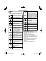 138
138
-
 139
139
-
 140
140
-
 141
141
-
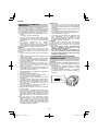 142
142
-
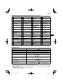 143
143
-
 144
144
-
 145
145
-
 146
146
-
 147
147
-
 148
148
-
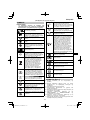 149
149
-
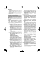 150
150
-
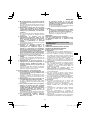 151
151
-
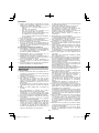 152
152
-
 153
153
-
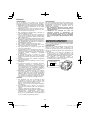 154
154
-
 155
155
-
 156
156
-
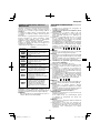 157
157
-
 158
158
-
 159
159
-
 160
160
-
 161
161
-
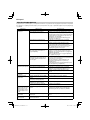 162
162
-
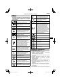 163
163
-
 164
164
-
 165
165
-
 166
166
-
 167
167
-
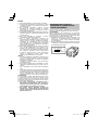 168
168
-
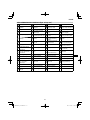 169
169
-
 170
170
-
 171
171
-
 172
172
-
 173
173
-
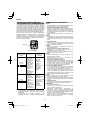 174
174
-
 175
175
-
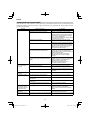 176
176
-
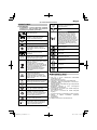 177
177
-
 178
178
-
 179
179
-
 180
180
-
 181
181
-
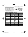 182
182
-
 183
183
-
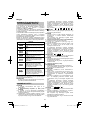 184
184
-
 185
185
-
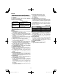 186
186
-
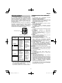 187
187
-
 188
188
-
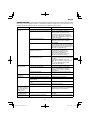 189
189
-
 190
190
-
 191
191
-
 192
192
-
 193
193
-
 194
194
-
 195
195
-
 196
196
-
 197
197
-
 198
198
-
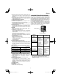 199
199
-
 200
200
-
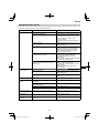 201
201
-
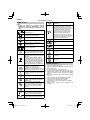 202
202
-
 203
203
-
 204
204
-
 205
205
-
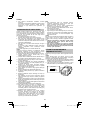 206
206
-
 207
207
-
 208
208
-
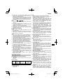 209
209
-
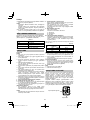 210
210
-
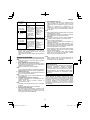 211
211
-
 212
212
-
 213
213
-
 214
214
-
 215
215
-
 216
216
-
 217
217
-
 218
218
-
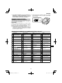 219
219
-
 220
220
-
 221
221
-
 222
222
-
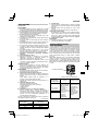 223
223
-
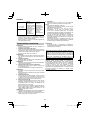 224
224
-
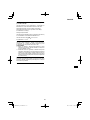 225
225
-
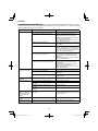 226
226
-
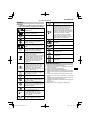 227
227
-
 228
228
-
 229
229
-
 230
230
-
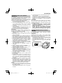 231
231
-
 232
232
-
 233
233
-
 234
234
-
 235
235
-
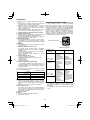 236
236
-
 237
237
-
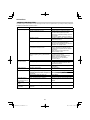 238
238
-
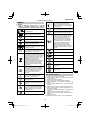 239
239
-
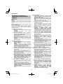 240
240
-
 241
241
-
 242
242
-
 243
243
-
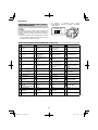 244
244
-
 245
245
-
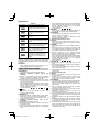 246
246
-
 247
247
-
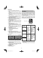 248
248
-
 249
249
-
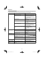 250
250
-
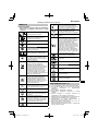 251
251
-
 252
252
-
 253
253
-
 254
254
-
 255
255
-
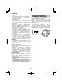 256
256
-
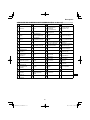 257
257
-
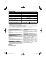 258
258
-
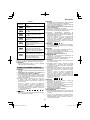 259
259
-
 260
260
-
 261
261
-
 262
262
-
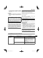 263
263
-
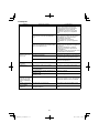 264
264
-
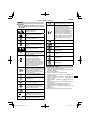 265
265
-
 266
266
-
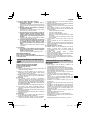 267
267
-
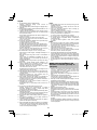 268
268
-
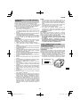 269
269
-
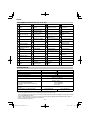 270
270
-
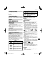 271
271
-
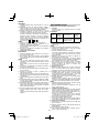 272
272
-
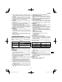 273
273
-
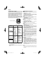 274
274
-
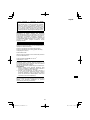 275
275
-
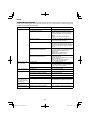 276
276
-
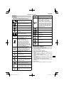 277
277
-
 278
278
-
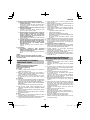 279
279
-
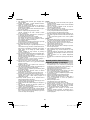 280
280
-
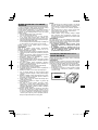 281
281
-
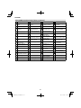 282
282
-
 283
283
-
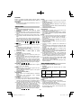 284
284
-
 285
285
-
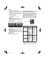 286
286
-
 287
287
-
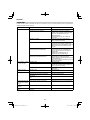 288
288
-
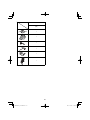 289
289
-
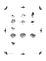 290
290
-
 291
291
-
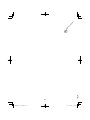 292
292
-
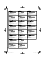 293
293
-
 294
294
-
 295
295
-
 296
296
-
 297
297
-
 298
298
-
 299
299
-
 300
300


Hikoki CG36DB(L) Manual de utilizare
- Categorie
- Unelte electrice
- Tip
- Manual de utilizare
- Acest manual este potrivit și pentru
în alte limbi
- slovenčina: Hikoki CG36DB(L) Používateľská príručka
- dansk: Hikoki CG36DB(L) Brugermanual
Lucrări înrudite
Alte documente
-
Hitachi CG 14DSDL Handling Instructions Manual
-
Dolmar AT1831U Manualul proprietarului
-
-
-
-
-
Makita BBC300L Manual de utilizare
-