Ubiquiti airFiber AF-24 Ghid de inițiere rapidă
- Tip
- Ghid de inițiere rapidă

24 GHz Point to Point
1.4+ Gbps Radio
Model: AF24


1
Introduction
Introduction
Thank you for purchasing the Ubiquiti Networks
™
airFiber
™
24GHz
Point-to-Point Radio, model AF24. This Quick Start Guide is
designed to guide you through the installation of the airFiber
AF24, show you how to access the airFiber Configuration Interface,
and explain how to set up an airFiber link.
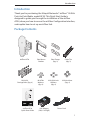
Package Contents
airFiber AF24 Pole Mount
Bracket
Pole Clamps
(Qty. 2)
Cable Ties
(Qty. 3)
M10x150
Carriage Bolts (Qty. 4)
M10 Flat
Washers
(Qty. 4)
M10 Split Lock
Washers
(Qty. 4)
M10 Hex Nuts
(Qty. 4)
24 GHz Point to Point
1.4+ Gbps Radio
Model: AF24
airFiber AF24
Quick Start Guide
PoE Adapter
(50V, 1.2A GigE)
Power Cord

2
airFiber
™
AF24 Quick Start Guide
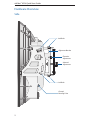
Hardware Overview
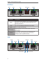
Side
Alignment Bracket
Elevation
Adjustment
Azimuth
Adjustment
Ground
Bonding Point
Lock Bolts
Lock Bolts

3
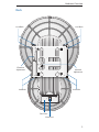
Hardware Overview
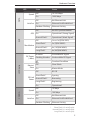
Back
Lock Bolts
Lock Bolts
Azimuth
Adjustment
Lock Bolts
Lock Bolts
Cover Lock
Elevation
Adjustment
Port Cover

4
airFiber
™
AF24 Quick Start Guide
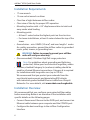
Interfaces
RESET DATA AUX CONFIGLED Display
Interface Description
RESET
To reset to factory defaults, press and hold the RESET
button for more than five seconds while the unit is
already powered on.
DATA 10/100/1000 Mbps port handles all user traffic.
AUX Port for audio tone aiming.
LED Display
Digital display used for power, status, and mode
information.
CONFIG
10/100 Mbps, secured port for configuration. By
default, this is the only port that can monitor,
configure, and/or update firmware.
LEDs
Link/Act
Speed
GPS
Modulation Link/Act
SpeedRX Power
Master/Slave RF Link Status

5
Hardware Overview
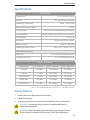
LED State Status
DATA
Speed
Off 10/100 Mbps
On 1000 Mbps
Link/Act
Off No Ethernet Link
On Ethernet Link Established
Random Flashing Ethernet Activity
AUX
GPS
Off No GPS Synchronization
On Operational (Strong Signal)
Normal Flash* Operational (Weak Signal)
Modulation
Off ¼x or 1x (QPSK SISO)
Short Flash* 2x (QPSK MIMO)
Normal Flash* 4x (16QAM MIMO)
Long Flash* 6x (64QAM MIMO)
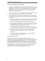
LED Display
RX Power
(-dBm)
Number Decodable RX Signal
Flashing Number Undecodable RX Signal
Overload Condition
Master/
Slave
Off Slave Mode
On Master Mode
RF Link
Status
Off RF Off
Short Flash* Syncing
Normal Flash* Beaconing
Long Flash* Registering
On Operational
CONFIG
Speed
Off 10 Mbps
On 100 Mbps
Link/Act
Off No Ethernet Link
On Ethernet Link Established
Random Flashing Ethernet Activity
* Short Flash (1:3 on/off cycle)
Normal Flash (1:1 on/off cycle)
Long Flash (3:1 on/off cycle)

6
airFiber
™
AF24 Quick Start Guide
Installation Requirements
• 17 mm wrench
• 13 mm socket wrench or driver
• Clear line of sight between airFiber radios
• Clear view of the sky for proper GPS operation
• Mounting location with < 0.5° displacement due to twist and
sway under wind loading
• Mounting point:
• At least 1 meter below the highest point on the structure
• For tower installations, at least 3 meters below the top of the
tower
• Ground wires – min. 8 AWG (10 mm
2
) and max. length: 1 meter.
As a safety precaution, ground the airFiber radios to grounded
masts, poles, towers, or grounding bars.
WARNING: Failure to properly ground your airFiber
units will void your warranty.
• (Recommended) 2 Outdoor GigE PoE surge protectors
Note: For guidelines about grounding and lightning
protection, follow your local electrical regulatory codes.
• Outdoor, shielded Category 5e (or above) cabling should be
used for all wired Ethernet connections. Category 6 is required
for installations with long cable runs (up to 100 m).
We recommend that you protect your networks from the
most brutal environments and devastating ESD attacks
with industrial-grade shielded Ethernet cable from Ubiquiti
Networks. For more details, visit www.ubnt.com/toughcable
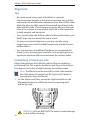
Installation Overview
We recommend that you configure your paired airFiber radios
before mounting. Below is an overview of the installation with
specific details on the following pages:
• Connect Power over Ethernet to the DATA port, and connect an
Ethernet cable between your computer and the CONFIG port.
• Configure the device settings in the airFiber Configuration
Interface.

7
Connecting Power over Ethernet
• Once configuration is complete, disconnect the cables to move
the airFiber radios.
• Reconnect at the site.
• After you have mounted the airFiber radios, establish and
optimize the RF link.
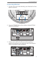
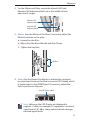
Connecting Power over Ethernet
1. Turn the Cover Lock to the Unlocked icon. Slide the Port Cover
down to remove it.
2. Connect an Ethernet cable to the DATA port.

8
airFiber
™
AF24 Quick Start Guide
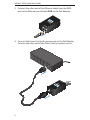
3. Connect the other end of the Ethernet cable from the DATA
port to the Ethernet port labeled POE on the PoE Adapter.
4. Connect the Power Cord to the power port on the PoE Adapter.
Connect the other end of the Power Cord to a power source.

9
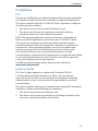
airFiber Configuration
airFiber
Configuration
The instructions in this section explain how to access the airFiber
Configuration Interface and configure the following settings:
• Wireless Mode Configure one airFiber AF24 as the Master and
the other as the Slave.
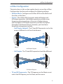
• Duplex The airFiber AF24 supports both half-duplex and
full-duplex operation. Half-duplex operation provides more
frequency planning options at the cost of higher latency
and throughput. Full-duplex operation provides the highest
throughput and lowest latency; however, you have fewer
frequency management options.
- Half Duplex (default) The TX and RX Frequencies can be the
same or different to suit local interference.
TX
RX
TX
RX
SlaveMaster
Frequency A
Frequency A
Half-Duplex Diagram
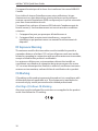
- Full Duplex The TX and RX Frequencies should be different.
TX
RX
TX
RX
SlaveMaster
Frequency A
Frequency B
Full-Duplex Diagram
• TX and RX Frequencies The TX Frequency on the Master must
match the RX Frequency on the Slave, and vice versa.

10
airFiber
™
AF24 Quick Start Guide
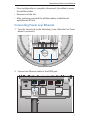
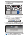
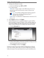
1. Connect an Ethernet cable from your computer to the CONFIG
port on the airFiber AF24.
2. Configure the Ethernet adapter on your computer with a
static IP address on the 192.168.1.x subnet (for example,
192.168.1.100).
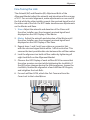
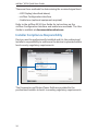
3. Launch your web browser. Type http://192.168.1.20 in the
address field and press enter (PC) or return (Mac).
4. The login screen will appear. Enter ubnt in the Username and
Password fields. Select your Country and Language. You must
agree to the Terms of Use to use the product. Click Login.
Note: U.S. product versions are locked to the U.S. Country
Code to ensure compliance with FCC regulations.

11
airFiber Configuration
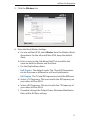
5. Click the Wireless tab.
6. Enter the Basic Wireless Settings:
a. For one airFiber AF24, select Master from the Wireless Mode
drop-down. For the other airFiber AF24, keep the default,
Slave.
b. Enter a name in the Link Name field. This should be the
same on both the Master and the Slave.
c. For the Duplex drop-down:
- Half Duplex The default mode. The TX and RX Frequencies
can be the same or different to suit local interference.
- Full Duplex The TX and RX Frequencies should be different.
d. Select a TX Frequency. This must match the RX Frequency on
your other airFiber AF24.
e. Select a RX Frequency. This must match the TX Frequency of
your other airFiber AF24.
f. If needed, change the Output Power, Maximum Modulation
Rate, and/or RX Gain settings.

12
airFiber
™
AF24 Quick Start Guide
7. Configure the Wireless Security:
a. Select the AES Key Type, HEX or ASCII.
b. For the Key field:
- HEX Enter 16 bytes (eight, 16-bit HEX values: 0-9, A-F, or
a-f). You can omit zeroes and use colons, similar to the
IPv6 format.
Note: The airFiber Configuration Interface supports
IPv6 formats excluding dotted quad and "::"
(double-colon) notation.
- ASCII Enter a combination of alphanumeric characters (0-9,
A-Z, or a-z).
8. Click Change and then click Apply.
9. In-Band Management is enabled by default, so each airFiber
radio must have a unique IP Address. (If the airFiber radios use
the same IP Address, then you may lose access to the airFiber
radios via the DATA ports.) To change the networksettings:
a. Click the Network tab.
b. Change the IP Address, Netmask, and other settings to make
them compatible with your network.
c. Click Change and then click Apply.
Repeat the instructions in the airFiber Configuration section on
your other airFiber radio. After you have configured the airFiber
radios, disconnect them and move them to your installation site.

13
Hardware Installation
Hardware Installation
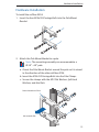
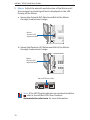
To install the airFiber AF24:
1. Insert the four M10x150 Carriage Bolts into the Pole Mount
Bracket.
2. Attach the Pole Mount Bracket to a pole.
Note: The mounting assembly can accommodate a
Ø 2.0" - 4.0" pole.
a. Orient the Pole Mount Bracket around the pole so it is aimed
in the direction of the other airFiber AF24.
b. Insert the M10x150 Carriage Bolts into the Pole Clamps.
c. Secure the clamps with the M10 Flat Washers, Split Lock
Washers, and Hex Nuts.
Note orientation of slots
Aim towards link.

14
airFiber
™
AF24 Quick Start Guide
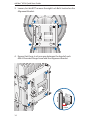
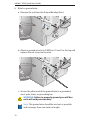
3. Loosen, but do NOT remove the eight Lock Bolts located on the
Alignment Bracket.
4. Ensure that there is a 6 mm gap between the head of each
M8x14 Serrated Flange Screw and the Alignment Bracket.
6 mm

15
Hardware Installation
5. Lift the airFiber AF24 and align the four M8x14 Serrated Flange
Screws with the slots on the Pole Mount Bracket. Seat the screws
in the slots. Securely tighten the screws.
WARNING: To prevent injury, ensure that all four screws
are seated and fully tightened.

16
airFiber
™
AF24 Quick Start Guide
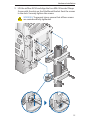
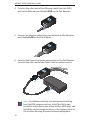
6. Attach a ground wire:
a. Remove the nut from the Ground Bonding Point.
b. Attach a ground wire (min. 8 AWG or 10 mm
2
) to the lug and
replace the nut to secure the wire.
c. Secure the other end of the ground wire to a grounded
mast, pole, tower, or grounding bar.
WARNING: Failure to properly ground your airFiber
units will void your warranty.
Note: The ground wire should be as short as possible
and no longer than one meter in length.

17
Connecting Ethernet
Connecting Ethernet
1. Turn the Cover Lock to the Unlocked icon. Slide the Port Cover
down to remove it.
2. Connect a TOUGHCable or other outdoor, shielded CAT5e/6
cable to the DATA port.
3. Create a strain relief for the Ethernet cable by feeding a
CableTie through the tie slot under the cable. Then wrap the
Cable Tie around the cable and tighten.

18
airFiber
™
AF24 Quick Start Guide
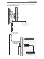
4. Connect the other end of the Ethernet cable from the DATA
port to the Ethernet port labeled POE on the PoE Adapter.
5. Connect an Ethernet cable from your network to the Ethernet
port labeled LAN on the PoE Adapter.
6. Connect the Power Cord to the power port on the PoE Adapter.
Connect the other end of the Power Cord to a power source.
Note: For added protection, we recommend installing
two GigE PoE surge protectors. Install the first surge
protector within one meter of the airFiber DATA port, and
install the second surge protector at the ingress point of
the location housing the wired network equipment.
Pagina se încarcă...
Pagina se încarcă...
Pagina se încarcă...
Pagina se încarcă...
Pagina se încarcă...
Pagina se încarcă...
Pagina se încarcă...
Pagina se încarcă...
Pagina se încarcă...
Pagina se încarcă...
Pagina se încarcă...
Pagina se încarcă...
Pagina se încarcă...
Pagina se încarcă...
Pagina se încarcă...
Pagina se încarcă...
-
 1
1
-
 2
2
-
 3
3
-
 4
4
-
 5
5
-
 6
6
-
 7
7
-
 8
8
-
 9
9
-
 10
10
-
 11
11
-
 12
12
-
 13
13
-
 14
14
-
 15
15
-
 16
16
-
 17
17
-
 18
18
-
 19
19
-
 20
20
-
 21
21
-
 22
22
-
 23
23
-
 24
24
-
 25
25
-
 26
26
-
 27
27
-
 28
28
-
 29
29
-
 30
30
-
 31
31
-
 32
32
-
 33
33
-
 34
34
-
 35
35
-
 36
36


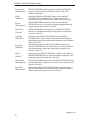
Ubiquiti airFiber AF-24 Ghid de inițiere rapidă
- Tip
- Ghid de inițiere rapidă
în alte limbi
Lucrări înrudite
-
Ubiquiti airFiber AF-24 Ghid de inițiere rapidă
-
Ubiquiti AF-5G23-S45 Ghid de inițiere rapidă
-
-
Ubiquiti airRouter HP Ghid de inițiere rapidă
-
Ubiquiti Networks AF-24 Manualul utilizatorului
-
-
-
-
-