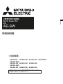
Mitsubishi Electric Low-Voltage Air Circuit Breakers series Type AE-SW Manual de utilizare
- Tip
- Manual de utilizare

18A
ENGLISH
CHINESE
中文
AE630-SW AE1000-SW AE1250-SW AE1600-SW
AE2000-SWA
AE2000-SW AE2500-SW AE3200-SW
AE4000-SWA
AE4000-SW AE5000-SW AE6300-SW
本手册适用于以下型号产品
使用说明书
対象機種
三菱低压空气断路器 World Super AE
MITSUBISHI Low-Voltage Air Circuit Breakers series
World Super AE
AE-SW
ご使用の前に必ずこの取扱説明書をお読みください。
この説明書は、最終ユーザまでお届けください。
IMPORTANT NOTE:
Before using these Series AE breakers, please read these
instructions carefully, and make sure that all actual users also read them.
JAPANESE
三菱低圧気中遮断器 World Super AE
取扱説明書
Types covered in this manual
重要注释: 在使用 AE 断路器系列以前,请务必仔细阅读本说明书,
并确保所有用户也阅读本说明。
MODEL
INSTRUCTION MANUAL

2
Failure to follow these in-
structions may result in dan-
gerous conditions, which in
turn could lead to severe
personal injury or even
death.
Failure to follow these instruc-
tions may result in dangerous
conditions, which could result
in moderate to slight personal
injury or damage to equip-
ments and facilities.
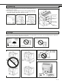
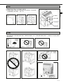
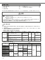
Safety precautions
Warning for possible electrification under
certain conditions.
¡Do not use this device on the conditions over ratings. Otherwise, ground-fault or short circuit fault could occur due to
dielectric breakdown. Or explosion could occur due to a short circuit protection failure.
¡Do not touch the terminals. There is a risk of electrical shock.
DANGER
CAUTION
¡Before using this device, make sure to read this Instruction manual thoroughly. The cautionary items noted herein are of
the utmost importance for the safe use of this device, and should always be strictly followed.
¡Please make sure that the final user receives this Instruction manual.
¡This Instruction manual is prepared for an electrical expert.
The following symbols have been used:
This means prohibition. Never ignore this
instruction.
Warning for possible outbreak of a fire
under certain conditions.
Be sure to follow these instructions with-
out fail.
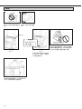
DANGER
CAUTION
¡A qualified electrician should install this equipment.
¡Inspection and maintenance should be performed by a qualified electrician and only after shutting off the electric power
and verifying that there is no voltage present. Failure to do so could result in an electrical shock.
¡Make sure to tighten the terminal screws to the torque specified in the instruction manual. Failure to do so could result
in fire.
¡Do not install in areas subject to high temperatures, high humidity, dust, corrosive gas, vibrations, or shocks, etc. To do
so could result in malfunction or fire.
¡Install so that trash, concrete dust, iron filings or rainwater cannot get into the circuit breaker unit interior. Failure to do
so could result in malfunction or fire.
¡When the circuit breaker trips automatically, always clear the source of the malfunction before closing the circuit
breaker. Failure to do so could result in fire.
¡Terminal screws should be tightened periodically. Failure to do so could result in fire.
¡Use the breaker in 50/60 Hz. Failure to do so could result in malfunction or fire.
¡Dispose of this product as industrial waste.

3
ENGLISH
Table of contents
¡Safety precautions ................................................. 2
¡External view .......................................................... 3
¡Internal construction ............................................... 4
¡Outline dimensions and Weight ............................. 4
¡Unpacking .............................................................. 5
¡Storage ................................................................... 5
¡Handling ................................................................. 6
¡Installation .............................................................. 7
¡Mount of drawout handle........................................ 8
¡Attach the Inter-phase Barrier ................................ 8
¡Connection ............................................................. 9
¡Insert operation .................................................... 11
¡Drawout operation ................................................ 13
¡Charging operation ............................................... 15
¡Opening/Closing operation .................................. 16
¡Door interlock (DI) ................................................ 18
¡Cylinder lock (CYL) and Castell lock (CAL) ......... 18
¡Shutter lock (SST-LOCK) ..................................... 19
¡Safety shutter name plate .................................... 19
¡Functions of electronic trip relay (ETR) parts ...... 20
¡Characteristics setting of type WS relay .............. 22
¡Characteristics setting of type WM relay ............. 23
¡Characteristics setting of type WB relay .............. 24
¡
Characteristic setting of optional setting module ...
25
¡Setting the operation characteristics .................... 27
¡Wiring diagram ..................................................... 29
¡
Technical note (Arc space, Reverse connection) ..
30
¡
Technical note (Performance of withstand voltage) ...
30
¡Technical note (Service conditions) ..................... 31
¡Guarantee ............................................................ 31
¡Inspection and Maintenance ................................ 32
¡Service Network ................................................... 38
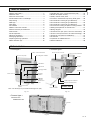
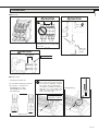
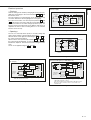
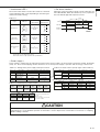
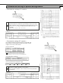
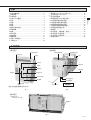
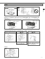
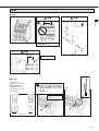
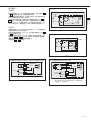
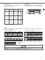
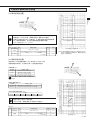
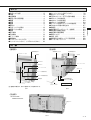
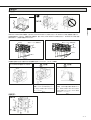
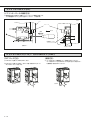
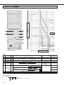
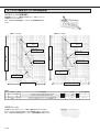
External view
< Fixed type >
Note: The fixed type is provided with lifting hooks (HP).
< Drawout type >
Fig. 3-1 Fig. 3-2
Cradle
Charging
handle
Drawout position indicator
Drawout handle aperture
Drawout handle
Extension rail
Control circuit connector
Control circuit terminal box
Drawout state
Arc-extinguish chamber
OFF button
ON buttons
Charging handle
Charging
indicator
ON/OFF
indicator
Rated name
plate
Manual reset button
(option)
Electronic trip relay
Pad lock hook
Control circuit terminal box
< Drawout type >
Fig. 3-3

4
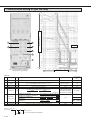
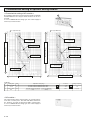
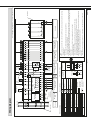
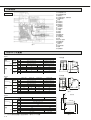
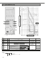
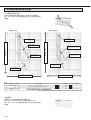
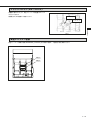
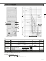
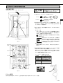
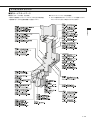
Internal construction
1Control circuit terminal block
2Control circuit connector
3Auxiliary switch
4Shunt trip device, closing coil
5Electronic trip relay
6Front cover
7Tripping mechanism
8Closing mechanism
9Charging mechanism
AClosing spring
BDrawout mechanism
CIntermediate base
DArc-extinguishing chamber
EMovable contact
FFixed contact
GConductor on the breaker
HConductor on the cradle
IMain circuit junction
JBase
KContact spring
LConductor on the breaker
MConductor on the cradle
NPower supply CT
OCurrent sensor coil
PCradle
QCradle name plate
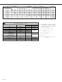
Table 4-1
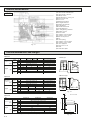
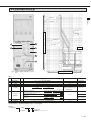
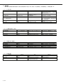
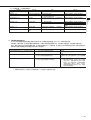
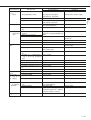
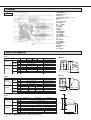
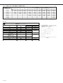
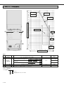
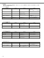
Outline dimensions and Weight
Type
AE630-SW
AE1000-SW AE1250-SW AE1600-SW
AE2000-SWA
340 ✕ 410 ✕ 290 ✕ 108
425 ✕ 410 ✕ 290 ✕ 108
300 ✕ 430 ✕ 375 ✕ 104
385 ✕ 430 ✕ 375 ✕ 104
47
57
70
84
31
35
340 ✕ 410 ✕ 290 ✕ 40
425 ✕ 410 ✕ 290 ✕ 40
300 ✕ 430 ✕ 375 ✕ 61
385 ✕ 430 ✕ 375 ✕ 61
40
50
63
77
42
52
65
79
41
51
64
78
26
30
Dimension
a ✕ b ✕ c ✕ d
(mm)
3P
4P
3P
4P
3P
4P
3P
4P
3P
4P
Weight
(kg)
Fixed
type
Drawout
type
Fixed
type
Drawout
type
Cradle
only
Table 4-2
Type AE2000-SW AE2500-SW AE3200-SW
60
72
92
113
35
43
61
73
93
114
63
75
95
116
36
44
AE4000-SWA
475 ✕ 410 ✕ 290 ✕ 117
605 ✕ 410 ✕ 290 ✕ 117
439 ✕ 430 ✕ 375 ✕ 109
569 ✕ 430 ✕ 375 ✕ 109
81
99
108
136
49
61
475 ✕ 410 ✕ 290 ✕ 40
605 ✕ 410 ✕ 290 ✕ 40
435 ✕ 430 ✕ 375 ✕ 61
565 ✕ 430 ✕ 375 ✕ 61
Dimension
a ✕ b ✕ c ✕ d
(mm)
3P
4P
3P
4P
3P
4P
3P
4P
3P
4P
Weight
(kg)
Fixed
type
Drawout
type
Fixed
type
Drawout
type
Cradle
only
AE-SW
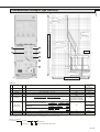
Fig. 4-1
¡Drawout type
Fig. 4-3
Fig. 4-4
¡Fixed type
Fig. 4-2
b
acd11
43
15 c d
40
a (MAX)
b
Drawout handle aperture
Drawout handle
Max.173
200
Cover position
169
200
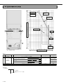
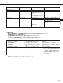
Type
Dimension
a ✕ b ✕ c ✕ d
(mm)
Weight
(kg)
Fixed
type
Drawout
type
Fixed
type
Drawout
type
Cradle
only
AE4000-SW AE5000-SW AE6300-SW
233
256
(
279
)
118
133
(
148
)
240
263
(
286
)
125
140
(
155
)
874 ✕ 414 ✕ 290 ✕ 136
1004
(
1134
)
✕ 414 ✕ 290 ✕ 136
875 ✕ 480 ✕ 375 ✕ 123
1005
(
1135
)
✕ 480 ✕ 375 ✕ 123
160
180
(
200
)
3P
4P
3P
4P
3P
4P
3P
4P
3P
4P
Table 4-3
( ) shows the value for 4P FN type, Neutral pole current capacity is 100% of the rated current.

5
ENGLISH
Accessories
nameplate
ETR accessories
Nameplate
CT rated
name plate
Rated
name plate
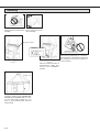
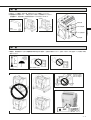
Storage
Unpacking
Fig. 5-1
1 Make sure that the packing case is free from any abnormality such as
breaking and/or wetting.
2 Referring to the rating nameplate, make sure that the delivered breaker
is in conformity with your order. Serial No. is indicated on the rated
name plate and the cradle name plate (Fig. 4-1Q).
Fig. 5-2 Fig. 5-3
Fig. 5-4
✽ When you start using the breaker after storage and if its storage period is over 6 years, use the ACB after grease lubrication.
Please contact to our service network how to grease.
Fig. 5-5 Fig. 5-6 Fig. 5-7
Fig. 5-8 Fig. 5-9
Fig. 5-10
Fig. 5-11
Fixed type Drawout type
OFF
+60°C
–20°C
H
2S ≤ 0.01ppm
SO2 ≤ 0.05ppm
NH3 ≤ 0.25ppm
Not attached
Average temperature for 24 hours,
however, shall not be higher than 35°C.
Avoid humid air.
Relative humidity : 85% max.

6
Handling
Fig. 6-1
Lifting hooks (HP)
Fig. 6-2
Never drop the breaker when
handling.
Never roll the breaker
when handling.
Fig. 6-3
Fixed type
Fig. 6-4
When the drawout breaker is
lifted with the cradle, lift it
when it is the “CONNECT”
position.
Drawout type
Fig. 6-5
When lifting and placing, be careful nei-
ther to drop nor to impact the breaker and
the terminals for the center of gravity is
by the terminal.
CONNECT position
Wire length: 1 m or more Wire length: 1 m or more
Fig. 6-6
To lift the breaker types AE4000-SW,
AE5000-SW and AE6300-SW, be sure to
use four ropes with a length of 1 m or
more, or use the lifting truck, apply for
further detail.
length ≥ 1 m

7
ENGLISH
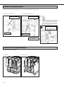
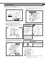
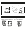
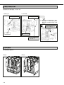
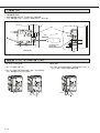
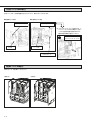
Installation
Tolerance on support flatness ≤ 1 mm
1 mm or less
Fig. 7-1
< Drawout type >
Fig. 7-2
M8
Earthing terminal
M12
M8
Earthing
terminal
M12
Fig. 7-8
< Fixed type >
Operate the drawout operation (CONNECT position to DRAWOUT position) according to instructions of drawout
operation. (Refer to P.13 and 14.)
Lifting by lifting truck or lifting hooks
Fig. 7-5
Fig. 7-6
CAUTION
Fig. 7-7
Lifting
Falling
On AE4000-SWA,AE4000-SW ~
AE6300-SW, the center of gravity of the
cradle is located at the terminal posi-
tion. When the main body is removed
from the cradle, the cradle may turn over
backward. Take measures against
overturning.
When the main body is drawn out,
the center of gravity shifts to the
front. If the cradle is not secured,
take measures against overturning
and dropping.
CAUTION
Fig. 7-3 Fig. 7-4
In the case of AE4000 ~ 6300-SW, insert four M12 bolts from the bottom and two M12 bolts from the back to mount the
cradle as shown in Fig. 7-3. In the case of 4P FN type, insert six M12 bolts from the bottom and two M12 bolts from the
back to mount the cradle as shown in Fig. 7-4.
AE4000 ~ 6300-SW 3P & 4P (HN) AE4000 ~ 6300-SW 4P (FN)
Mounting angle (Non-magnetic)
2-M12
6-M12
2-M12
4-M12
Mounting angle (Non-magnetic)
Cradle
Support

8
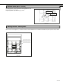
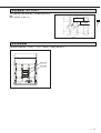
Fig. 8-1 Fig. 8-2
Fig. 8-4
Note: The drawout handle cannot be mounted
on the left side of the cradle when the
cradle is provided with a mechanical
inter lock (MI) or a door inter lock (DI).
Mount the handle at an appropriate
position in the panel.
Cradle
Handle holder
Drawout handle
Mtg. Screw M5 ✕ 12
2.8 ~ 3.6 N·m
Nut M5
Mechanical interlock (MI)
or
door interlock (DI)
¡Mounting on the left side ¡Mounting on the right side
Mount of drawout handle
The drawout handle can be mounted on any of the left and right sides of the cradle.
Attach the Inter-phase Barrier
Insert in the slot on the breaker.
Fig. 8-3
<Fixed type> <Drawout type>
Fig. 8-5

9
ENGLISH
M3.5 ✕ 10
Torque: 0.8 ~ 1.2Nm
Max. 200 mm
Fixing support
25mm
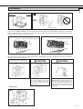
Connection
■Main circuit
Fig. 9-1
Use small washers to connect that
the washers do not overlap with
each other.
Fig. 9-3
Fig. 9-2
M12
40 ~ 50N·m
Conductor
If the screw is tightened with exces-
sive torque, the terminal and the
screw may be damaged. Tighten
the screw to the specified torque.
Screwdrivers should be used whose
diameters are of size suited to the
diameters of the cruciform grooves.
Size of toolhead : PH2
Fig. 9-4
■Control circuit
¡Crimp-type terminal size
Recommended crimp-type terminals
Ex.1.25 mm
2
~ 2.0 mm
2
wires
N2-M3(RAP2-3.5) (JST)
FN2-M3(RBP2-3.5) (JST)
N2-YS3A(JST)
Fig. 9-5 Fig. 9-6 Fig. 9-7
Passage wiring
Max. 7.2 mm
ACB termi-
nal (silver-
plated)
CAUTION CAUTION
CAUTION

10
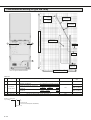
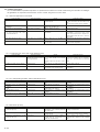
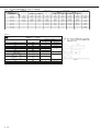
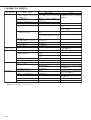
Table 10-1 Electromagnetic force in N per 1 m conductor (3-phase short circulation)
Type
Conductor distance (mm)
Prospective fault current
kA (pf)
(N)
Drawout type Fixed type
30 (0.2)
42 (0.2)
50 (0.2)
65 (0.2)
75 (0.2)
85 (0.2)
100 (0.2)
130 (0.2)
AE630-SW
~
AE1600-SW
85
7,700
15,100
21,400
36,100
—
—
—
—
3P
115
5,700
11,200
15,800
26,700
—
—
—
—
4P
105
6,300
12,200
17,300
29,300
—
—
—
—
3P
190
3,500
6,800
9,600
16,200
21,500
27,600
—
—
4P
170
3,900
7,600
10,700
18,100
24,100
30,900
—
—
3P
152
4,300
8,500
12,000
20,200
26,900
34,500
—
—
4P
145
4,500
8,900
12,600
21,200
28,200
36,200
—
—
AE2000-SWA
AE4000-SWAAE2000-SW
~
AE3200-SW
130
5,100
9,900
14,000
23,600
31,500
40,400
—
—
AE4000-SW
~
AE6300-SW
262
2,500
5,000
7,000
11,800
15,800
20,000
27,800
47,000
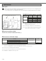
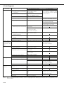
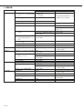
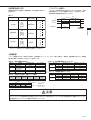
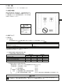
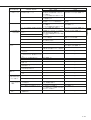
Table 10-2
Conductor size (IEC60947-1)
(40°C ambient temperature, open air)
Note: Table 10-2 shows conductor size based
on IEC 60947-1 in ambient temperature
40°C and open air. And the examination
circuit is as Fig. 10-1
Rated current max. (A)
630
1000
1250
1600
2000
2500
3200
4000 (AE4000-SW)
5000
6300
Arrangement
Vertical
Vertical
Vertical
Vertical
Vertical
Vertical
Vertical
Vertical
Vertical
Vertical
Vertical
Vertical
Connecting conductors (Copper bus bar)
Quantity
2
2
2
2
3
4
3
3
4
4
4
4
Conductor size (mm)
40 ✕ 5
60 ✕ 5
80 ✕ 5
100 ✕ 5
100 ✕ 10
150 ✕ 10
100 ✕ 10
150 ✕ 10
200 ✕ 10
AE4000-SWA
Fixed type
AE4000-SWA
Drawout type
4000
4000
Fig. 10-1
3m
2m

11
ENGLISH
Using a lifter or ropes
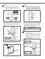
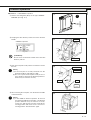
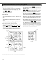
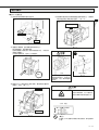
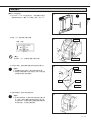
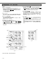
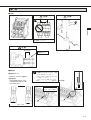
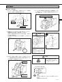
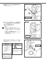
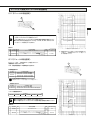
Insert operation
■DISCONNECT → CONNECT position
1 Release the lock levers, and pull the extension rails for-
ward.
2 Place the breaker on the extension rails, using a lifter or
ropes. Mount the concave of the breaker in the rail pro-
truding portion. (Fig. 11-5)
Fig. 11-1
1
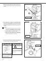
3 Slowly push the breaker in unit it does not move.
To insert the breaker, push each side equally.
Otherwise (in the case of inserting slantwise) the breaker
can not move smoothly.
When ACB is installed at a high position, please do the
Drawout / Insert operation by two people.
Fig. 11-3
3
4 Keeping the OFF button pushed, insert the drawout handle.
Make sure that the drawout position indicator shows “DIS-
CONNECT” (Fig. 11-7).
Fig. 11-2
2
Falling
Shut finger
Take care not to shut finger be-
tween extension rails and switch
board when the breaker is insert.
DISCONNECT position
(Prohibition)
Do not insert the drawout handle unless the OFF but-
ton is pushed.
There is a possibility of damaging.
Extension rails
Lock levers
Click!
Concave of the breaker
Projection of the rail
Fig. 11-5
Fig. 11-4
Fig. 11-7
If the breaker main body is put
on the rails with the cradle un-
secured, the center of gravity
shifts to the front. Take mea-
sures against overturning.
CAUTION
CAUTION
4
OFF button
Push
Insert
Drawout handle
Fig. 11-6

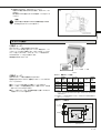
12
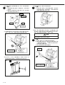
TEST position
Latch
Release
position
Cover
Push
Lock plate
Lock position
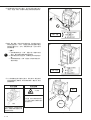
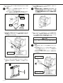
5 Push the lock plate in fully until it is latched to release
the lock.
(Note:)
(a) If the lock plate is not fully released, turn the
drawout handle to right and left a little.
(b) Be sure to push the lock plate in fully to release
position, otherwise the drawout position indicator
may not function collectoly.
Fig. 12-1
7 When the breaker is inserted to the test position, the
drawout position indicator shows TEST position, and the
lock plate automatically protrudes to lock the drawout
handle.
Fig. 12-3
7
Insert the breaker until the lock plate protrudes. If it does
not protruding, the breaker may not be connected com-
pletely.
6 After releasing the lock plate, turn the drawout handle
clockwise.
(Note:)
(a) Do not try to pull the unit out while inserting it as
doing so may not accurately display the posi-
tion. If the unit is pulled out in the middle of the
inserting process, pull it out to the circuit dis-
connecting position and then insert it again.
Fig. 12-2
6
8 Then, push the lock plate to turn the handle clockwise.
When the breaker is inserted to the connect position,
the lock plate automatically protrudes to indicate that
the breaker has been inserted completely. The drawout
position indicator shows CONNECT position.
(Note:)
(a) After insertion is completed, do not turn the
drawout handle further.
(b) The drawout position indicator shows the position
(CONNECT or TEST) of the breaker at the time
when the lock plate protrudes. When the lock
plate is in the released state, the indicator shows
the reference position.
(c) It is impossible to close the breaker when insert-
ing the drawout handle.
8
Check 1
The lock plate is jutted
out.
Automatic
Check 2
CONNECT (Connection)
position
Fig. 12-4
CAUTION
5
9
Fig. 12-5
9 For the AE4000 ~ 6300-SW series (See Fig. 12-5), shall
be sure to tighten the screws on both sides to secure
the breaker.

13
ENGLISH
OFF button
Push
Drawout handle
Drawout operation
2 Keeping the OFF button pushed, insert the drawout
handle.
Fig. 13-3
2
(Prohibition)
Do not insert the drawout handle unless the OFF
button is pushed.
3 Push the lock plate in fully until it is latched to release
the lock.
(Note:)
(a) If the lock plate is not fully released, turn the
drawout handle to right and left a little.
(b) Be sure to push the lock plate in fully to the re-
lease position, otherwise the drawout position in-
dicator may not function correctly.
4 After releasing the lock plate, turn the drawout handle
counterclockwise.
(Note:)
(a) In the middle of drawout operation, do not turn
the drawout handle insert operation. The drawout
position indicator may not function correctly.
In this case, pull the unit out to the circuit discon-
necting position and insert it to the circuit con-
necting position. Then drawout it again.
CONNECT position
Fig. 13-2
1
Fig. 13-1
1 Remove two fixing bolts (M12) for the types AE4000 ~
6300-SW. (See Fig. 13-1)
■CONNECT → DISCONNECT position
Lock plate
Latch
Cover
Push
Lock position
Release
position
Fig. 13-4
3
Fig. 13-5
4

14
Click!
Lock lever
TEST position
Automatic
5 When the breaker is drawn out to the test position, the
drawout position indicator shows TEST position, and the
lock plate automatically protrudes to lock the drawout
handle.
Fig. 14-1
5
6 Then, push in the lock plate, turn the drawout handle
counterclockwise to change the displayed extraction
position to the DISCONNECT position until the drawout
position indicator shows disconnect position. The handle
operation is completed. The breaker can be drawn out
by hand.
(Note:)
(a) The lock plate may project before the breaker
moves to the DISCONNECT position. Push the
lock plate in and continue to operate the handle.
(b) If the lock plate is not fully released, turn the
drawout handle to right and left a little.
(c) When the breaker is drawn out to the DISCON-
NECT position, the drawout handle is idly rotated
and the lock plate does not protrude.
7 To remove the breaker main body from the cradle, pull
the lock levers toward you to unlock the main body, pull
the rails toward you, and draw out the breaker.
Fig. 14-2
6
Fig. 14-4
7
Take care not to shut finger be-
tween extension rails and switch
board when the breaker is
drawn out.
Shut finger
Falling
DISCONNECT
position
Fig. 14-3
When the main body is drawn
out, the center of gravity shifts
to the front. If the cradle is not
secured, take measures against
overturning and falling.
CAUTION
CAUTION

15
ENGLISH
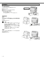
Charging operation
Fig. 15-3
¡Manual charging operation is also possible using the charg-
ing handle.
¡Although the charging motor has a short time rating it can
be continuously operated for up to ten times.
¡Since the charging complete switch is separate from the
motor charging circuit, the sequence can be arranged as
required.
Fig. 15-2
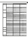
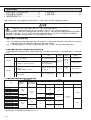
Table 15-1 Motor charging rating
< Motor charging >
The closing spring is electrically charged.
This is an “ON charge method”, in which the spring is auto-
matically charged when the breaker is closed.
Rated
voltage
(V)
Applicable
voltage
range (V)
Applied
voltage
(V)
Inrush
current
(peak) (A)
Steady
current
(A)
Charging
time
Criterion for
power
requirement
(VA)
24 DC
48 DC
100-125
AC/DC
200-250
AC/DC
18-26.4
36-52.8
85-137.5
170-275
24
48
100
125
200
250
22
14
10 (10)
12 (12)
5 (7)
6 (8)
6
3
3 (4)
3 (4)
1 (2)
1 (2)
5 sec or
less
500
700
1000
700
1000
Note 1: Contents in parentheses show the case of AE4000-SWA 4-pole,
AE4000-SW, AE5000-SW and AE6300-SW.
24 V DC and 48 V DC products of AE4000-SWA 4-pole, AE4000-SW,
AE5000-SW and AE6300-SW cannot be manufactured.
Note 2: Operating power supply capacity of the motor charging should be
prepared not to be lower than an applicable voltage range during
charging.
< Manual charging >
Press the charging handle down at full stroke 7 or 8 times
until a click sounds. (It is completion when a charging handle
becomes light.) Then, the closing spring will be fully charged.
The charging indicator will show CHARGED.
The operating load is 30 N·m or less.
Charge operation: 7 to 8 times
MD circuit diagram
Charging
completion
Switch output
M
Apply for further of 24 V DC and 48 V DC.
Breaker
Control
relay
Motor charging
circuit
Charging limit
switch
Charging completion switch
Motor
Control
supply
413
414
U1
U2
8 To drawout the breaker, pull each side equally.
Otherwise (in the case of drawing slantwise) the breaker
can not move smoothly.
When ACB is installed at a high position, please do the
Drawout / Insert operation by two people.
(Note:)
Since the center of gravity is by the terminal, the
Cradle support is required to prevent from falling.
(See Fig. 15-1)
Fig. 15-1
8
Cradle support

16
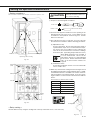
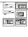
Fig. 16-1
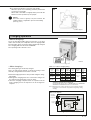
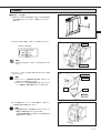
Opening/Closing operation
< Conditions of ON operation >
ON operation will be possible, when all the following condi-
tions have fulfilled.
Manual operation
< Closing >
Push the ON button, the breaker will close. The ON/OFF
indicator will show “ON”, and the charging indicator will show
“DISCHARGED”. Operating force is less than 50N.
(Note:)
When the OFF lock device (Padlock, cylinder lock,
castell lock etc.) is used, the closing operation should
be made after the lock is released.
Opening and closing of the drawout type breaker
must be carried out in either the CONNECT or the
TEST position.
If an under voltage trip device (UVT) is provided, its
rated voltage should be applied before attempting to
close and open the breaker.
< Opening >
Push the OFF button, the breaker will be opened and the
ON/OFF indicator will show “OFF”. Operating force is less
than 50N.
Fig. 16-2
Fig. 16-3
OFF
non-OFF instructions
ON
ON
OFF
OFF
¡The breaker is OFF condition.
¡The closing spring is charged.
The charging indicator shows “CHARGED”.
¡The state without OFF operations.
•
Without SHT operation
•Without mechanical lock (Padlock, Cylinder lock, Mechanical in-
terlock etc.)
•UVT controller power is supplied and no operation with trip ter-
minals.

17
ENGLISH
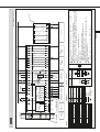
Control supply
Fig. 17-1
Power supply
A1
A2
Air circuit breaker
Min. 80ms
CC Unit
CC
One pulse
circuit
Note: 24 to 48 V DC does not have rectifier circuit.
SHT circuit diagram
Fig. 17-2
Note: 24 to 48 V DC does not have rectifier
circuit.
Power supply
Air circuit breaker Cut-off
switch
SHT unit
SHT
C1
C2
Min. 40ms
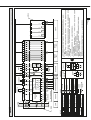
UVT circuit diagram (for 380-460 V AC)
Fig. 17-4
UVT circuit diagram (for 100-120 V AC, 200-240 V AC or
DC voltage)
Fig. 17-3
Note: Use a pushbutton for tripping having power ratings of
150 V DC and 0.5 A or more.
D1
D2
UVT
controller
UVT
coil
Push button
for tripping
Min 0.2s
Max. 2m
Air circuit breaker
DT1
DT2
D1
D2
IN1
IN2
OUT3
OUT4
UVT
controller
UVT
coil
External
unit
Air circuit breaker
Note: Use a pushbutton for tripping having power ratings of
150 V DC and 0.5 A or more.
The external transformer dedicated for AE-SW is used.
Only one UVT controller can be connected to one
external unit.
Max. 2m
DT1
DT2
Push button
for tripping
Min 0.2s
Electrical operation
< Closing >
Remote closing can be made by emerging the closing coil (CC).
Apply the rated voltage to the control terminals A1 , A2 , and
the breaker closes.
The unit comprises an unti-pumping circuit which allows only
one action without first de-energizing then re-energizing.
To re-close the breaker, once turn off power (between A1 and
A2 ) to the closing coil, and re-apply the rated voltage to them.
When the breaker has an under-voltage trip device (UVT), the
breaker cannot be closed if power is not applied. (After power is
applied to the UVT, it takes a waiting time of 1.5 sec until the
breaker can be closed.)
< Opening >
The use of a shunt trip device (SHT) or an under-voltage trip
device (UVT) enables to electrically trip the breaker.
When an SHT is used, apply the rated voltage to C1 and C2 on
the control circuit terminal block.
When a UVT is used, open the trip terminals DT1 and DT2 on
the control circuit terminal block. (A short-circuiting bar has been
fitted before shipment. Remove the bar before using the termi-
nals.)
Or turn off an applied voltage to D1 and D2 .

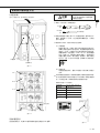
18
< Procedures for releasing door interlock >
1 Even when the breaker is on, the interlock can be manually released.
For this purpose, make a hole 7 or more in diameter in the panel door. (See the following figure.)
Release
Door
5
When the breaker is on
(5)
40
20
View A
Door hook
Direction A
Hole for releasing 7 or
more in diameter
Cylinder lock (CYL) and Castell Lock (CAL)
< Procedures for locking in off state >
1 Press the OFF button to turn off the ACB.
2 Hold down the OFF button and turn the key to the locking
side. Then, the key can be removed, and the breaker will
be locked in the off state.
Door interlock (DI)
Lock
OFF
OFF
OFF
OFF
< Releasing procedures >
1 Insert the key, and turn the key to the releasing side.
If the key cannot be turned smoothly, hold down the OFF
button and turn the key to the releasing side.
Release
OFF
OFF
Fig. 18-1
Fig. 18-2
Fig. 18-3
Fig. 18-4
(mm)

19
ENGLISH
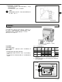
Shutter lock (SST-LOCK)
The safety shutter can be locked at the closing position so that
the live parts are not touched.
Prepare a pad lock (5 in diameter) by yourself.
Pad lock (f5)
Shutter lock
Fig. 19-1
Safety shutter name plate
Please refer to a lower figure, if you need to attach the sticker “BUSBARS” and “CABLES” included in the package of the safety shutter.
Fig. 19-2
Bundled name plate
Bundled name plate

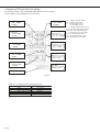
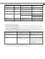
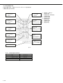
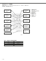
20
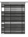
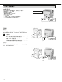
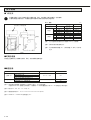
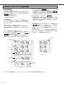
< Functions >
1 ERR. LED, Contact alarm output
When any abnormality or setting failure is found in ETR,
the LED alerts the operators to the abnormal status. When
the power type is P3 to P5, contact output is given be-
tween
513
and
574
on the control circuit terminal block.
•ETR function (Microprocessor, H/W)
•Mis-setting of INST. /MCR dial (P.27)
•Internal wiring of breaker related to ETR
2 RUN LED (ETR)
This LED indicates that ETR is functional. When control
power is applied or approx. 10% of current flows into the
main circuit, the internal circuit will start, and the LED will
light.
3 RUN LED (Optional setting module)
This LED indicates that the optional setting module is func-
tional.
When the control power is applied or approx. 10% of the
main circuit current flows, the LED will light.
4 Trip indicator (LED and contact alarm output)
The LED indicates the tripping or pre-alarm status. When
the power supply type is P3 to P5, contact output is given
between
513
(common) and
524
,
534
,
544
and
554
on
the control circuit terminal block.
When the current exceeds pre-alarm current setting (Ip),
the PAL LED will blink. When the LTD time (1/2 of TL) is
passed, the PAL LED will light and output the contact.
As for the display and interface unit, see the separate instruction manual.
3RUN LED
(GFR)
5TAL LED
4LED indicating
cause of tripping
4LED indicating
cause of tripping
1ERR. LED
2RUN LED
(ETR)
7RESET
button
6MCR
Do not
set
5 TAL LED and contact output
Option
The ETR temperature detector is made functional by fit-
ting a TAL sensor.
When the power type is P3 to P5, output is given between
513
and
564
on the control circuit terminal block. When
the temperature drops, the output will be reset. To retain
the output, take measures with an external sequence.
6 MCR (Making current release)
Option
Only when the breaker is turned on (from the off state), it
has the INST function. After it is turned on, the INST func-
tion will be disabled. If you specify the use of MCR when
placing an order, the MCR switch will be incorporated in
the main body. MCR will be functional by setting the INST
setting dial of ETR to the MCR side. (Refer to Fig. 20-2)
7 Reset button
The trip indicator (LED and contact alarm output) can be
reset by pressing the “RESET” button on the front panel
of ETR or short-circuiting
RS1
and
RS2
on the control cir-
cuit terminal block.
(P1 and P2 types are not provided with the function to
reset the indication from the control circuit terminal block.)
A function is provided to temporarily lock LTD and STD
when the INST function is tested with the field test device.
(See the breaker tester instruction manual.)
Fig. 20-1
Functions of electronic trip relay (ETR) parts
Fig. 20-2
Pagina se încarcă...
Pagina se încarcă...
Pagina se încarcă...
Pagina se încarcă...
Pagina se încarcă...
Pagina se încarcă...
Pagina se încarcă...
Pagina se încarcă...
Pagina se încarcă...
Pagina se încarcă...
Pagina se încarcă...
Pagina se încarcă...
Pagina se încarcă...
Pagina se încarcă...
Pagina se încarcă...
Pagina se încarcă...
Pagina se încarcă...
Pagina se încarcă...
Pagina se încarcă...
Pagina se încarcă...
Pagina se încarcă...
Pagina se încarcă...
Pagina se încarcă...
Pagina se încarcă...
Pagina se încarcă...
Pagina se încarcă...
Pagina se încarcă...
Pagina se încarcă...
Pagina se încarcă...
Pagina se încarcă...
Pagina se încarcă...
Pagina se încarcă...
Pagina se încarcă...
Pagina se încarcă...
Pagina se încarcă...
Pagina se încarcă...
Pagina se încarcă...
Pagina se încarcă...
Pagina se încarcă...
Pagina se încarcă...
Pagina se încarcă...
Pagina se încarcă...
Pagina se încarcă...
Pagina se încarcă...
Pagina se încarcă...
Pagina se încarcă...
Pagina se încarcă...
Pagina se încarcă...
Pagina se încarcă...
Pagina se încarcă...
Pagina se încarcă...
Pagina se încarcă...
Pagina se încarcă...
Pagina se încarcă...
Pagina se încarcă...
Pagina se încarcă...
Pagina se încarcă...
Pagina se încarcă...
Pagina se încarcă...
Pagina se încarcă...
Pagina se încarcă...
Pagina se încarcă...
Pagina se încarcă...
Pagina se încarcă...
Pagina se încarcă...
Pagina se încarcă...
Pagina se încarcă...
Pagina se încarcă...
Pagina se încarcă...
Pagina se încarcă...
Pagina se încarcă...
Pagina se încarcă...
Pagina se încarcă...
Pagina se încarcă...
Pagina se încarcă...
Pagina se încarcă...
Pagina se încarcă...
Pagina se încarcă...
Pagina se încarcă...
Pagina se încarcă...
Pagina se încarcă...
Pagina se încarcă...
Pagina se încarcă...
Pagina se încarcă...
Pagina se încarcă...
Pagina se încarcă...
Pagina se încarcă...
Pagina se încarcă...
Pagina se încarcă...
Pagina se încarcă...
Pagina se încarcă...
Pagina se încarcă...
Pagina se încarcă...
Pagina se încarcă...
Pagina se încarcă...
Pagina se încarcă...
Pagina se încarcă...
Pagina se încarcă...
Pagina se încarcă...
Pagina se încarcă...
-
 1
1
-
 2
2
-
 3
3
-
 4
4
-
 5
5
-
 6
6
-
 7
7
-
 8
8
-
 9
9
-
 10
10
-
 11
11
-
 12
12
-
 13
13
-
 14
14
-
 15
15
-
 16
16
-
 17
17
-
 18
18
-
 19
19
-
 20
20
-
 21
21
-
 22
22
-
 23
23
-
 24
24
-
 25
25
-
 26
26
-
 27
27
-
 28
28
-
 29
29
-
 30
30
-
 31
31
-
 32
32
-
 33
33
-
 34
34
-
 35
35
-
 36
36
-
 37
37
-
 38
38
-
 39
39
-
 40
40
-
 41
41
-
 42
42
-
 43
43
-
 44
44
-
 45
45
-
 46
46
-
 47
47
-
 48
48
-
 49
49
-
 50
50
-
 51
51
-
 52
52
-
 53
53
-
 54
54
-
 55
55
-
 56
56
-
 57
57
-
 58
58
-
 59
59
-
 60
60
-
 61
61
-
 62
62
-
 63
63
-
 64
64
-
 65
65
-
 66
66
-
 67
67
-
 68
68
-
 69
69
-
 70
70
-
 71
71
-
 72
72
-
 73
73
-
 74
74
-
 75
75
-
 76
76
-
 77
77
-
 78
78
-
 79
79
-
 80
80
-
 81
81
-
 82
82
-
 83
83
-
 84
84
-
 85
85
-
 86
86
-
 87
87
-
 88
88
-
 89
89
-
 90
90
-
 91
91
-
 92
92
-
 93
93
-
 94
94
-
 95
95
-
 96
96
-
 97
97
-
 98
98
-
 99
99
-
 100
100
-
 101
101
-
 102
102
-
 103
103
-
 104
104
-
 105
105
-
 106
106
-
 107
107
-
 108
108
-
 109
109
-
 110
110
-
 111
111
-
 112
112
-
 113
113
-
 114
114
-
 115
115
-
 116
116
-
 117
117
-
 118
118
-
 119
119
-
 120
120


Mitsubishi Electric Low-Voltage Air Circuit Breakers series Type AE-SW Manual de utilizare
- Tip
- Manual de utilizare
în alte limbi
Alte documente
-
Phcbi MPR-514R Instrucțiuni de utilizare
-
Rittal SK 3303.470 Assembly And Operating Instructions Manual
-
-
Eaton CEAG ZB-S Mounting And Operating Instructions
-
Yamaha P2150 Manualul proprietarului
-
-
Miele APWM 061 Manual de utilizare
-
Suzuki Jimny Manualul proprietarului
-
Samsung HT-D6750WK Manual de utilizare
-
Samsung HT-D7500W Manualul utilizatorului