
In-Wall Manageable
Switch/Dimmer
Model: mFi-LD
www.4Gon.co.uk [email protected] Tel: +44 (0)1245 808295 Fax: +44 (0)1245 808299

Introduction
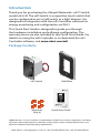
Thank you for purchasing the Ubiquiti Networks
™
mFi®Switch,
model mFi-LD. The mFi Switch is a capacitive touch switch that
can be configured as an on/off switch or a light dimmer. It is
designed for integration with the mFiController software for
energy monitoring and configuration via Wi-Fi.
This Quick Start Guide is designed to guide you through
the hardware installation and software configuration. The
warranty terms are also included in this Quick Start Guide. For
details on using the mFi Controller or to download the mFi
Controller software, visit www.ubnt.com/mfi
Package Contents
mFi Switch Wall Plate
In-Wall Manageable
Switch/Dimmer
Model: mFi-LD
Wire Nuts
(Qty. 4)
Quick Start Guide
TERMS OF USE: It is the customer’s responsibility to follow local country regulations, including
operation within legal frequency channels, output power, indoor cabling requirements, and
Dynamic Frequency Selection (DFS) requirements.
www.4Gon.co.uk [email protected] Tel: +44 (0)1245 808295 Fax: +44 (0)1245 808299

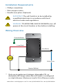
Installation Requirements
• Phillips screwdriver
• Wire stripper/cutter
• Needle-nose pliers (Optional)
IMPORTANT: The mFi Switch is to be installed by
a qualified electrician in accordance with local
electrical codes and regulations.
WARNING: TO AVOID FIRE, SHOCK OR DEATH; turn off
power at the circuit breaker or fuse before installing.
Wiring Overview
Hot (Black)
Ground (Green)
Load (Red)
Neutral (White)
120V, 60 Hz
* Only use incandescent, halogen, dimmable CFL, or
dimmable LED lamps when the mFi Switch is configured
as a light dimmer. Maximum Load is 5A in Dimmer mode.
*
www.4Gon.co.uk [email protected] Tel: +44 (0)1245 808295 Fax: +44 (0)1245 808299

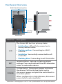
Hardware Overview
Initialize
Button
Air Gap
Switch
Status LED
Wall Plate Mounting Slots
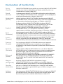
Interface Description
LED
The Status LED has four primary states:
• Solid yellow When first powered on in
factory default mode.
• Flashing yellow Connecting to a Wi-Fi
network.
• Solid blue Successfully connected to mFi
Controller.
• Flashing blue Connecting to mFi Controller.
INIT
Initialize Button Restores to factory default
settings. Press and hold until the LED alternates
colors to restore the device.
POWER
Air Gap Switch Disconnects power and resets
the device. Pull the Air Gap Switch out to
disconnect power and push the switch back in
to restore power.
When configured as a light dimmer, disconnect
power before replacing bulbs.
www.4Gon.co.uk [email protected] Tel: +44 (0)1245 808295 Fax: +44 (0)1245 808299

Hardware Installation
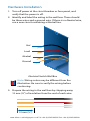
1. Turn off power at the circuit breaker or fuse panel, and
verify that the power is off.
2. Identify and label the wiring in the wall box. There should
be three wires and a ground wire. If there is no Neutral wire,
run a new circuit containing a Neutral line.
Hot
Load
Neutral
Ground
Electrical Switch Wall Box
Note: Wiring colors may be different from the
illustration. Be sure to verify the wiring before
continuing.
3. Prepare the wiring in the wall box by stripping away
12mm(½") of insulation from the end of each wire.
12 mm (½")
www.4Gon.co.uk [email protected] Tel: +44 (0)1245 808295 Fax: +44 (0)1245 808299

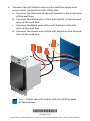
4. Connect the mFi Switch wires to the wall box wires and
secure each connection with a Wire Nut.
a. Connect the Red wire of the mFi Switch to the Load wire
of the wall box.
b. Connect the White wire of the mFi Switch to the Neutral
wire of the wall box.
c. Connect the Black wire of the mFi Switch to the Hot
wire of the wall box.
d. Connect the Green wire of the mFi Switch to the Ground
wire of the wall box.
Note: Orient the mFi Switch with the LED located
at the bottom.
*720-00077-01*
720-00077-01
www.4Gon.co.uk [email protected] Tel: +44 (0)1245 808295 Fax: +44 (0)1245 808299

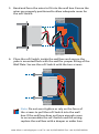
5. Bend and form the wires to fit into the wall box. Ensure the
wires are properly positioned to allow adequate room for
the mFi Switch.
6. Place the mFi Switch inside the wall box and ensure the
yoke is mounted flush with the wall for proper fitting of the
Wall Plate. Secure the mFi Switch with the two screws.
Note: Do not over-tighten or rely on the force of
the screws to pull the mFi Switch into the wall
box. If the wall box does not have enough room
to accommodate the mFi Switch and the wiring,
replace the wall box with a deeper or wider box.
www.4Gon.co.uk [email protected] Tel: +44 (0)1245 808295 Fax: +44 (0)1245 808299

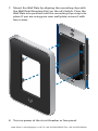
7. Mount the Wall Plate by aligning the mounting clips with
the Wall Plate Mounting Slots on the mFi Switch. Press the
Wall Plate into position until the mounting clips snap into
place. If you are using your own wall plate, secure it with
two screws.
8. Turn on power at the circuit breaker or fuse panel.
www.4Gon.co.uk [email protected] Tel: +44 (0)1245 808295 Fax: +44 (0)1245 808299

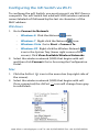
Configuring the mFi Switch via Wi-Fi
To configure the mFi Switch, you must access it via Wi-Fi from a
computer. The mFi Switch has a default SSID (wireless network
name) labeled mFi followed by the last six characters of the
MAC address.
Windows
1. Go to Connect to Network.
- Windows 8 Click the Network
icon.
- Windows 7 Right-click the Network icon.
- Windows Vista Go to Start > Connect To.
- Windows XP Right-click the Wireless Network
icon in the System Tray (lower right corner of the
screen). Click View Available Wireless Networks.
2. Select the wireless network (SSID) that begins with mFi
and then click Connect. Go to Accessing the Configuration
Portal.
Mac
1. Click the AirPort icon in the menu bar (top right side of
the screen).
2. Select the wireless network (SSID) that begins with mFi.
Once connected, the AirPort icon will change from gray
to solid black.
www.4Gon.co.uk [email protected] Tel: +44 (0)1245 808295 Fax: +44 (0)1245 808299

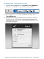
Accessing the Configuration Portal
1. Launch your web browser. Type https://192.168.2.20 in
the address field. Press enter (PC) or return (Mac).
2. You may receive a security certificate warning. Click
Proceed Anyway.
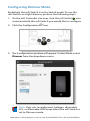
3. The Configuration Portal will appear. Select the wireless
network name (SSID) of your existing wireless network
from the drop-down list. To refresh the list, click the blue
arrows on the right.
www.4Gon.co.uk [email protected] Tel: +44 (0)1245 808295 Fax: +44 (0)1245 808299

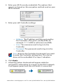
4. Enter your Wi-Fi security credentials. The options that
appear are based on the encryption method used on your
Wi-Fi network.
5. Enter your mFi Controller settings:
• Address The IP address and http port used by
the Controller. (The port is usually 6080, for
example: 1.1.1.1:6080 or mfi.acme.com:6080).
• User The username used to log in to the
Controller.
• Password The password used to log in to the
Controller.
Note: Remove the Controller checkmark if you need
to enter the Controller settings later. This can be
done via the embedded UI or layer 2 adoption.
6. Click Apply.
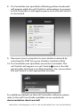
7. A flashing yellow checkmark will appear while the
mFiSwitch is attempting to connect to the Wi-Fi network.
It will appear green once the mFi Switch is connected.
www.4Gon.co.uk [email protected] Tel: +44 (0)1245 808295 Fax: +44 (0)1245 808299

8. If a Controller was specified, a flashing yellow checkmark
will appear while the mFi Switch is attempting to connect
to the Controller. It will appear green once the mFi Switch
is connected.
9. Reconnect your computer to your wireless network by
selecting the SSID from your wireless network utility.
10. If a Controller was specified, access the Controller. The
mFiSwitch will appear as a mFi Switch
icon in the left
panel under the Drag on to Map heading. You can position
the mFi Switch in the appropriate location.
For additional details on the mFi Controller software, please
refer to the mFi User Guide available on our website at:
documentation.ubnt.com/mfi
www.4Gon.co.uk [email protected] Tel: +44 (0)1245 808295 Fax: +44 (0)1245 808299

Configuring Dimmer Mode
By default, the mFi Switch is set to Switch mode. To use the
mFiSwitch as a light dimmer, perform the following steps:
1. On the mFi Controller site map, click the mFi Switch
icon
associated with the mFiSwitch you would like to configure.
2. Click the Configuration icon.
3. The Configuration window will appear. Under Mode, select
Dimmer from the dropdown menu.
Note: Only use incandescent, halogen, dimmable
CFL, or dimmable LED lamps when the mFi Switch is
set to Dimmer mode.
www.4Gon.co.uk [email protected] Tel: +44 (0)1245 808295 Fax: +44 (0)1245 808299

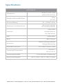
Specifications
mFi Switch
Dimensions
110.8 x 71 x 67.7 mm
(4.32 x 2.8 x 2.67 in)
Weight (without Wall Plate)
150 g
(5.3 oz)
Electrical Rating 110 - 125VAC, 60 Hz
Maximum Combined Load
15A in Switch Mode
5A in Dimmer Mode
Interface
Status LED
Initialize Button
Air Gap Switch
LED Yellow/Blue
Wi-Fi 802.11b/g/n
Functions
Switch or Dimmer Mode
Energy Monitoring
ESD/EMP Protection Air: ±8KV, Contact: ±4KV
Operating Temperature
0 to 40° C
(32 to 104° F)
Operating Humidity 10 to 95% Non-Condensing
Shock and Vibration -40° C, 2 Hrs / +85° C, 2 Hrs, 5 Cycles
www.4Gon.co.uk [email protected] Tel: +44 (0)1245 808295 Fax: +44 (0)1245 808299

Safety Notices
1. Read, follow, and keep these instructions.
2. Heed all warnings.
3. Only use attachments/accessories specified by the manufacturer.
WARNING: Do not use this product in location that can
be submerged by water.
WARNING: Avoid using this product during an electrical
storm. There may be a remote risk of electric shock from
lightning.
Electrical Safety Information
1. Compliance is required with respect to voltage, frequency, and current
requirements indicated on the manufacturer’s label. Connection to a
different power source than those specified may result in improper
operation, damage to the equipment or pose a fire hazard if the
limitations are not followed.
2. There are no operator serviceable parts inside this equipment. Service
should be provided only by a qualified service technician.
3. The equipment requires the use of the ground wire as a part of the
safety certification, modification or misuse can provide a shock hazard
that can result in serious injury or death.
4. Contact a qualified electrician or the manufacturer if there are
questions about the installation prior to connecting the equipment.
5. Protective bonding must be installed in accordance with local national
wiring rules and regulations.
www.4Gon.co.uk [email protected] Tel: +44 (0)1245 808295 Fax: +44 (0)1245 808299

Limited Warranty
UBIQUITI NETWORKS, Inc (“UBIQUITI NETWORKS”) warrants that the
product(s) furnished hereunder (the “Product(s)”) shall be free from defects
in material and workmanship for a period of one (1) year from the date
of shipment by UBIQUITI NETWORKS under normal use and operation.
UBIQUITI NETWORKS’ sole and exclusive obligation and liability under
the foregoing warranty shall be for UBIQUITI NETWORKS, at its discretion,
to repair or replace any Product that fails to conform to the above
warranty during the above warranty period. The expense of removal and
reinstallation of any Product is not included in this warranty. The warranty
period of any repaired or replaced Product shall not extend beyond its
original term.
Warranty Conditions
The above warranty does not apply if the Product:
(I) has been modified and/or altered, or an addition made thereto,
except by Ubiquiti Networks, or Ubiquiti Networks’ authorized
representatives, or as approved by Ubiquiti Networks in writing;
(II) has been painted, rebranded or physically modified in any way;
(III) has been damaged due to errors or defects in cabling;
(IV) has been subjected to misuse, abuse, negligence, abnormal physical,
electromagnetic or electrical stress, including lightning strikes, or
accident;
(V) has been damaged or impaired as a result of using third party
firmware;
(VI) has no original Ubiquiti MAC label, or is missing any other original
Ubiquiti label(s); or
(VII) has not been received by Ubiquiti within 30 days of issuance of
the RMA.
In addition, the above warranty shall apply only if: the product has been
properly installed and used at all times in accordance, and in all material
respects, with the applicable Product documentation; all Ethernet cabling
runs use CAT5 (or above), and for outdoor installations, shielded Ethernet
cabling is used, and for indoor installations, indoor cabling requirements
are followed.
Returns
No Products will be accepted for replacement or repair without obtaining
a Return Materials Authorization (RMA) number from UBIQUITI NETWORKS
during the warranty period, and the Products being received at UBIQUITI
NETWORKS’ facility freight prepaid in accordance with the RMA process of
UBIQUITI NETWORKS. Products returned without an RMA number will not
be processed and will be returned freight collect or subject to disposal.
Information on the RMA process and obtaining an RMA number can be
found at: www.ubnt.com/support/warranty.
www.4Gon.co.uk [email protected] Tel: +44 (0)1245 808295 Fax: +44 (0)1245 808299

Disclaimer
EXCEPT FOR ANY EXPRESS WARRANTIES PROVIDED HEREIN, UBIQUITI
NETWORKS, ITS AFFILIATES, AND ITS AND THEIR THIRD PARTY DATA,
SERVICE, SOFTWARE AND HARDWARE PROVIDERS HEREBY DISCLAIM
AND MAKE NO OTHER REPRESENTATION OR WARRANTY OF ANY KIND,
EXPRESS, IMPLIED OR STATUTORY, INCLUDING, BUT NOT LIMITED TO,
REPRESENTATIONS, GUARANTEES, OR WARRANTIES OF MERCHANTABILITY,
ACCURACY, QUALITY OF SERVICE OR RESULTS, AVAILABILITY,
SATISFACTORY QUALITY, LACK OF VIRUSES, QUIET ENJOYMENT, FITNESS
FOR A PARTICULAR PURPOSE AND NON-INFRINGEMENT AND ANY
WARRANTIES ARISING FROM ANY COURSE OF DEALING, USAGE OR
TRADE PRACTICE IN CONNECTION WITH SUCH PRODUCTS AND SERVICES.
BUYER ACKNOWLEDGES THAT NEITHER UBIQUITI NETWORKS NOR
ITS THIRD PARTY PROVIDERS CONTROL BUYER’S EQUIPMENT OR THE
TRANSFER OF DATA OVER COMMUNICATIONS FACILITIES, INCLUDING
THE INTERNET, AND THAT THE PRODUCTS AND SERVICES MAY BE
SUBJECT TO LIMITATIONS, INTERRUPTIONS, DELAYS, CANCELLATIONS
AND OTHER PROBLEMS INHERENT IN THE USE OF COMMUNICATIONS
FACILITIES. UBIQUITI NETWORKS, ITS AFFILIATES AND ITS AND THEIR THIRD
PARTY PROVIDERS ARE NOT RESPONSIBLE FOR ANY INTERRUPTIONS,
DELAYS, CANCELLATIONS, DELIVERY FAILURES, DATA LOSS, CONTENT
CORRUPTION, PACKET LOSS, OR OTHER DAMAGE RESULTING FROM ANY
OF THE FOREGOING. In addition, UBIQUITI NETWORKS does not warrant
that the operation of the Products will be error-free or that operation will
be uninterrupted. In no event shall UBIQUITI NETWORKS be responsible
for damages or claims of any nature or description relating to system
performance, including coverage, buyer’s selection of products (including
the Products) for buyer’s application and/or failure of products (including
the Products) to meet government or regulatory requirements.
Limitation of Liability
EXCEPT TO THE EXTENT PROHIBITED BY LOCAL LAW, IN NO EVENT WILL
UBIQUITI OR ITS SUBSIDIARIES, AFFILIATES OR SUPPLIERS BE LIABLE FOR
DIRECT, SPECIAL, INCIDENTAL, CONSEQUENTIAL OR OTHER DAMAGES
(INCLUDING LOST PROFIT, LOST DATA, OR DOWNTIME COSTS), ARISING
OUT OF THE USE, INABILITY TO USE, OR THE RESULTS OF USE OF THE
PRODUCT, WHETHER BASED IN WARRANTY, CONTRACT, TORT OR OTHER
LEGAL THEORY, AND WHETHER OR NOT ADVISED OF THE POSSIBILITY OF
SUCH DAMAGES.
www.4Gon.co.uk [email protected] Tel: +44 (0)1245 808295 Fax: +44 (0)1245 808299

Note
Some countries, states and provinces do not allow exclusions of implied
warranties or conditions, so the above exclusion may not apply to you.
You may have other rights that vary from country to country, state to
state, or province to province. Some countries, states and provinces do not
allow the exclusion or limitation of liability for incidental or consequential
damages, so the above limitation may not apply to you. EXCEPT TO
THE EXTENT ALLOWED BY LOCAL LAW, THESE WARRANTY TERMS DO
NOT EXCLUDE, RESTRICT OR MODIFY, AND ARE IN ADDITION TO, THE
MANDATORY STATUTORY RIGHTS APPLICABLE TO THE LICENSE OF ANY
SOFTWARE (EMBEDDED IN THE PRODUCT) TO YOU. The United Nations
Convention on Contracts for the International Sale of Goods shall not apply
to any transactions regarding the sale of the Products.
Compliance
FCC
NOTE: This equipment has been tested and found to comply with the limits
for a Class B digital device, pursuant to part 15 of the FCC Rules. These
limits are designed to provide reasonable protection against harmful
interference in a residential installation. This equipment generates, uses
and can radiate radio frequency energy and, if not installed and used in
accordance with the instructions, may cause harmful interference to radio
communications. However, there is no guarantee that interference will
not occur in a particular installation. If this equipment does cause harmful
interference to radio or television reception, which can be determined by
turning the equipment off and on, the user is encouraged to try to correct
the interference by one or more of the following measures:
• Reorient or relocate the receiving antenna.
• Increase the separation between the equipment and receiver.
• Connect the equipment into an outlet on a circuit different from that to
which the receiver is connected.
• Consult the dealer or an experienced radio/TV technician for help.
www.4Gon.co.uk [email protected] Tel: +44 (0)1245 808295 Fax: +44 (0)1245 808299

Industry Canada
This Class B digital apparatus complies with Canadian ICES-003.
To reduce potential radio interference to other users, the antenna
type and its gain should be so chosen that the equivalent isotropically
radiated power (EIRP) is not more than that permitted for successful
communication.
This device complies with Industry Canada licence-exempt RSS standard(s).
Operation is subject to the following two conditions:
1. This device may not cause interference, and
2. This device must accept any interference, including interference that
may cause undesired operation of the device.
Cet appareil numérique de la classe B est conforme à la norme NMB-003
du Canada.
Pour réduire le risque d’interférence aux autres utilisateurs, le type
d’antenne et son gain doivent être choisies de façon que la puissance
isotrope rayonnée équivalente (PIRE) ne dépasse pas ce qui est nécessaire
pour une communication réussie.
Cet appareil est conforme à la norme RSS Industrie Canada exempts de
licence norme(s). Son fonctionnement est soumis aux deux conditions
suivantes:
1. cet appareil ne peut pas provoquer d’interférences et
2. cet appareil doit accepter toute interférence, y compris les
interférences qui peuvent causer un mauvais fonctionnement du
dispositif.
CAN ICES-3(B)/NMB-3(B)
Changes or modifications not expressly approved by the party responsible
for compliance could void the user‘s authority to operate the equipment.
RF Exposure Warning
The transceiver described here emits radio frequency energy. Although the
power level is low, the concentrated energy from a directional antenna may
pose a health hazard. Do not allow people to come closer than 20 cm to the
antenna when the transmitter is operating.
Additional information on RF exposure is available on the Internet at
www.fcc.gov/oet/info/documents/bulletins
L’émetteur-récepteur décrit ici émet de l’énergie de fréquence radio.
Bien que le niveau de puissance est faible, l’énergie concentrée à partir
d’une antenne directionnelle peut présenter un danger pour la santé. Ne
pas permettre aux gens de se rapprocher de 20 cm à l’antenne lorsque
l’émetteur est en marche.
Des renseignements supplémentaires sur l’exposition aux RF est disponible
sur Internet à www.fcc.gov/oet/info documents/bulletins
www.4Gon.co.uk [email protected] Tel: +44 (0)1245 808295 Fax: +44 (0)1245 808299

RoHS/WEEE Compliance Statement
English
European Directive 2002/96/EC requires that the equipment bearing
this symbol on the product and/or its packaging must not be disposed
of with unsorted municipal waste. The symbol indicates that this
product should be disposed of separately from regular household waste
streams. It is your responsibility to dispose of this and other electric and
electronic equipment via designated collection facilities appointed by the
government or local authorities. Correct disposal and recycling will help
prevent potential negative consequences to the environment and human
health. For more detailed information about the disposal of your old
equipment, please contact your local authorities, waste disposal service, or
the shop where you purchased the product.
Deutsch
Die Europäische Richtlinie 2002/96/EC verlangt, dass technische
Ausrüstung, die direkt am Gerät und/oder an der Verpackung mit diesem
Symbol versehen ist, nicht zusammen mit unsortiertem Gemeindeabfall
entsorgt werden darf. Das Symbol weist darauf hin, dass das Produkt
von regulärem Haushaltmüll getrennt entsorgt werden sollte. Es
liegt in Ihrer Verantwortung, dieses Gerät und andere elektrische
und elektronische Geräte über die dafür zuständigen und von der
Regierung oder örtlichen Behörden dazu bestimmten Sammelstellen zu
entsorgen. Ordnungsgemäßes Entsorgen und Recyceln trägt dazu bei,
potentielle negative Folgen für Umwelt und die menschliche Gesundheit
zu vermeiden. Wenn Sie weitere Informationen zur Entsorgung Ihrer
Altgeräte benötigen, wenden Sie sich bitte an die örtlichen Behörden oder
städtischen Entsorgungsdienste oder an den Händler, bei dem Sie das
Produkt erworben haben.
www.4Gon.co.uk [email protected] Tel: +44 (0)1245 808295 Fax: +44 (0)1245 808299
Pagina se încarcă ...
Pagina se încarcă ...
Pagina se încarcă ...
Pagina se încarcă ...
-
 1
1
-
 2
2
-
 3
3
-
 4
4
-
 5
5
-
 6
6
-
 7
7
-
 8
8
-
 9
9
-
 10
10
-
 11
11
-
 12
12
-
 13
13
-
 14
14
-
 15
15
-
 16
16
-
 17
17
-
 18
18
-
 19
19
-
 20
20
-
 21
21
-
 22
22
-
 23
23
-
 24
24


în alte limbi
- English: Ubiquiti MFI-LD Quick start guide
- italiano: Ubiquiti MFI-LD Guida Rapida
Lucrări conexe
-
Ubiquiti Networks mPower mini Fișa cu date
-
Ubiquiti MPORT Ghid de inițiere rapidă
-
-
Ubiquiti MFI-MSC Ghid de inițiere rapidă
-
-
-
-
Ubiquiti UAP-PRO Ghid de inițiere rapidă
-
-