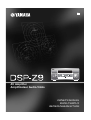
Yamaha DSP-Z9 Manualul proprietarului
- Categorie
- Receptoare AV
- Tip
- Manualul proprietarului

GB
PHONO
DVR
STANDBY
/ON
PURE DIRECT
2CH/MULTI CH
SPEAKERS
VIDEO AUX
REC OUT/ZONE 2
INPUT MODE
SOURCE/REMOTE
DVDDTV/LD
MD/TAPE
CD-R
TUNER
CD
VIDEO AUX
VCR 2
VCR 1
SAT
CABLE
A B
STRAIGHT
EFFECT
MULTI CH
INPUT
DSP
PROGRAM
BALANCE
TONE
CONTROL
VOLUME
INPUT SELECTOR
MULTI JOG
SILENT OPTIMIZER
MIC
PHONES
OPTICAL
R
AUDIO
L
VIDEO
S VIDEO
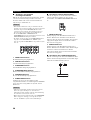
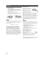
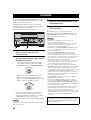
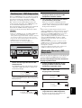
AV Amplifier
Amplificateur Audio-Vidéo
OWNER’S MANUAL
MODE D’EMPLOI
BEDIENUNGSANLEITUNG

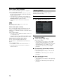
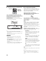
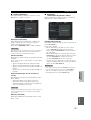
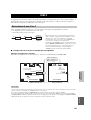
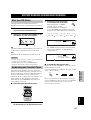
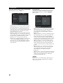
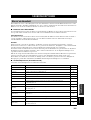
1 To assure the finest performance, please read this
manual carefully. Keep it in a safe place for future
reference.
2 Install this sound system in a well ventilated, cool,
dry, clean place — away from direct sunlight, heat
sources, vibration, dust, moisture, and/or cold.
Allow ventilation space of at least 30 cm on the top,
20 cm on the left and right, and 20 cm on the back
of this unit.
3 Locate this unit away from other electrical
appliances, motors, or transformers to avoid
humming sounds.
4 Do not expose this unit to sudden temperature
changes from cold to hot, and do not locate this
unit in a environment with high humidity (i.e. a
room with a humidifier) to prevent condensation
inside this unit, which may cause an electrical
shock, fire, damage to this unit, and/or personal
injury.
5 Avoid installing this unit where foreign object may
fall onto this unit and/or this unit may be exposed
to liquid dripping or splashing. On the top of this
unit, do not place:
– Other components, as they may cause damage
and/or discoloration on the surface of this unit.
– Burning objects (i.e. candles), as they may
cause fire, damage to this unit, and/or personal
injury.
– Containers with liquid in them, as they may fall
and liquid may cause electrical shock to the user
and/or damage to this unit.
6 Do not cover this unit with a newspaper, tablecloth,
curtain, etc. in order not to obstruct heat radiation.
If the temperature inside this unit rises, it may
cause fire, damage to this unit, and/or personal
injury.
7 Do not plug in this unit to a wall outlet until all
connections are complete.
8 Do not operate this unit upside-down. It may
overheat, possibly causing damage.
9 Do not use force on switches, knobs and/or cords.
10 When disconnecting the power cord from the wall
outlet, grasp the plug; do not pull the cord.
11 Do not clean this unit with chemical solvents; this
might damage the finish. Use a clean, dry cloth.
12 Only voltage specified on this unit must be used.
Using this unit with a higher voltage than specified
is dangerous and may cause fire, damage to this
unit, and/or personal injury. YAMAHA will not be
held responsible for any damage resulting from use
of this unit with a voltage other than specified.
13 To prevent damage by lightning, disconnect the
power cord from the wall outlet during an electrical
storm.
14 Do not attempt to modify or fix this unit. Contact
qualified YAMAHA service personnel when any
service is needed. The cabinet should never be
opened for any reasons.
15 When not planning to use this unit for long periods
of time (i.e. vacation), disconnect the AC power
plug from the wall outlet.
16 Be sure to read the “TROUBLESHOOTING” section
on common operating errors before concluding
that this unit is faulty.
17 Before moving this unit, press STANDBY/ON to set
this unit in the standby mode, and disconnect the
AC power plug from the wall outlet.
18 VOLTAGE SELECTOR (General model only)
The VOLTAGE SELECTOR on the rear panel of this
unit must be set for your local main voltage
BEFORE plugging into the AC main supply.
Voltages are 110/120/220/230-240 V AC, 50/60 Hz.
■ For U.K. customers
If the socket outlets in the home are not suitable for the
plug supplied with this appliance, it should be cut off and
an appropriate 3 pin plug fitted. For details, refer to the
instructions described below.
The plug severed from the mains lead must be destroyed, as a
plug with bared flexible cord is hazardous if engaged in a live
socket outlet.
■ Special Instructions for U.K. Model
CAUTION: READ THIS BEFORE OPERATING YOUR UNIT.
This unit is not disconnected from the AC power
source as long as it is connected to the wall outlet, even
if this unit itself is turned off. This state is called the
standby mode. In this state, this unit is designed to
consume a very small quantity of power.
WARNING
TO REDUCE THE RISK OF FIRE OR ELECTRIC
SHOCK, DO NOT EXPOSE THIS UNIT TO RAIN
OR MOISTURE.
Note
IMPORTANT
THE WIRES IN MAINS LEAD ARE COLOURED IN
ACCORDANCE WITH THE FOLLOWING CODE:
Blue: NEUTRAL
Brown: LIVE
As the colours of the wires in the mains lead of this
apparatus may not correspond with the coloured
markings identifying the terminals in your plug,
proceed as follows:
The wire which is coloured BLUE must be connected
to the terminal which is marked with the letter N or
coloured BLACK. The wire which is coloured
BROWN must be connected to the terminal which is
marked with the letter L or coloured RED.
Making sure that neither core is connected to the earth
terminal of the three pin plug.

1
English
PREPARATIONINTRODUCTION
BASIC
OPERATION
SOUND FIELD
PROGRAMS
ADVANCED
OPERATION
ADDITIONAL
INFORMATION
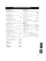
FEATURES .............................................................2
GETTING STARTED............................................3
Supplied accessories .................................................. 3
Installing batteries in the remote controls.................. 4
CONTROLS AND FUNCTIONS.......................... 5
Front panel ................................................................. 5
Remote control........................................................... 7
GUI remote control.................................................... 8
Using the remote controls .......................................... 9
Front panel display................................................... 10
Rear panel ................................................................ 11
SPEAKER SETUP................................................ 12
Speaker placement ................................................... 12
Speaker connections ................................................ 13
CONNECTIONS...................................................16
Connecting components........................................... 16
Connecting video components................................. 17
Connecting audio components................................. 24
Connecting the power supply cord .......................... 27
Speaker impedance setting....................................... 28
Turning on the power............................................... 28
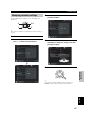
USING THE GUI REMOTE CONTROL..........29
GUI remote control operations ................................ 29
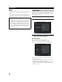
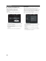
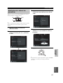
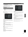
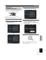
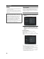
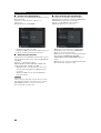
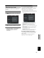
AUTO SETUP....................................................... 31
Introduction.............................................................. 31
Optimizer microphone setup.................................... 31
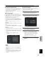
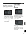
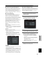
Starting the setup ..................................................... 32
Confirming the results ............................................. 34
PLAYBACK ..........................................................37
Basic operations....................................................... 37
Selecting sound field programs................................ 39
Listening to uncompromising pure audio ................ 43
Selecting input modes.............................................. 44
RECORDING ....................................................... 46
SOUND FIELD PROGRAM
DESCRIPTIONS.............................................. 48
For movie/video sources.......................................... 48
For music sources .................................................... 51
ADVANCED OPERATIONS.............................. 53
Selecting the OSD mode.......................................... 53
Using the sleep timer ............................................... 53
Using the test tone.................................................... 54
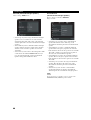
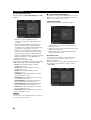
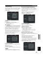
SYSTEM OPTIONS............................................. 55
Changing parameter settings.................................... 57
Input Select .............................................................. 58
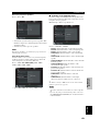
Manual setup: Sound ............................................... 61
Manual setup: Basic................................................. 64
Manual setup: Video................................................ 71
Manual setup: Option............................................... 75
Memory Guard......................................................... 78
REMOTE CONTROL FEATURES................... 80
Control area.............................................................. 80
Setting manufacturer codes...................................... 81
Programming codes from other remote controls ..... 82
Changing source names in the display window....... 83
Using the macro feature........................................... 84
Clearing function sets .............................................. 86
Clearing individual functions................................... 87
Controlling components........................................... 88
ZONE 2.................................................................. 93
Zone 2 connections .................................................. 93
Remote controlling Zone 2 ...................................... 94
USING i.LINK...................................................... 96
What is i.LINK?....................................................... 96
Connecting i.LINK components.............................. 96
Assigning i.LINK components ................................ 97
Listening to playback from an i.LINK
component ........................................................... 97
Changing i.LINK Select parameters........................ 98
i.LINK display messages ....................................... 100
SOUND FIELD OPTIONS................................ 101
What is a sound field ............................................. 101
Stereo/Surround menu ........................................... 103
TROUBLESHOOTING..................................... 108
PARAMETRIC EQUALIZER
INFORMATION ............................................ 112
GLOSSARY ........................................................ 113
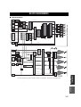
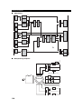
BLOCK DIAGRAMS ........................................ 117
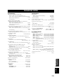
SPECIFICATIONS............................................ 119
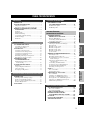
CONTENTS
INTRODUCTION
PREPARATION
BASIC OPERATION
SOUND FIELD PROGRAMS
ADVANCED OPERATION
ADDITIONAL INFORMATION

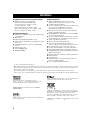
FEATURES
2
Built-in 9-channel power amplifier
◆ Minimum RMS output power
(0.015% THD, 20 Hz – 20 kHz, 8Ω)
Front: 170 W + 170 W
Center: 170 W
Surround: 170 W + 170 W
Surround back: 170 W + 170 W
Presence: 50 W + 50 W
Sound field features
◆ Proprietary YAMAHA technology for the creation of
sound fields
◆ THX Ultra 2
◆ Dolby Digital/Dolby Digital EX decoder
◆ Dolby Pro Logic/Dolby Pro Logic II/Dolby Pro Logic
IIx decoder
◆ DTS/DTS ES Matrix 6.1, Discrete 6.1/DTS 96/24
decoder
◆ DTS Neo:6 decoder
◆ Virtual CINEMA DSP
◆ SILENT CINEMA
™
Other features
◆ YPAO: YAMAHA Parametric Room Acoustic
Optimizer for automatic speaker setup
◆ 192-kHz/24-bit D/A converter
◆ On-screen display menus that allow you to optimize
this unit to suit your individual audio/video system
◆ 8-channel external decoder input for other future
formats (compatible with DSP)
◆ PURE DIRECT for pure fidelity sound with multi or
2-channel sources
◆ On-screen display function with dedicated GUI remote
control for performing all operations
◆ S Video signal input/output capability
◆ Component video input/output capability
◆ Video signal conversion (Composite video ↔
S Video ↔ Component video) capability for monitor
out
◆ Faroudja DCDi for progressive video output
◆ Faroudja True Life Enhancer for smooth video images
◆ TBC (Time Base Corrector) for jitterless video images
◆ i.LINK interface for direct digital transfer of digital
audio signals
◆ Optical and coaxial digital audio signal jacks
◆ Sleep timer
◆ Night listening mode
◆ Remote control with preset manufacturer codes and
“learning” macro capability
◆ Zone 2 custom installation facility
• y indicates a tip for your operation.
• Some operations can be performed by using either the buttons on the main unit or on the remote control. In cases where the button
names differ between the main unit and remote control, the button name on the remote control is given in parentheses.
• This manual is printed prior to production. Design and specifications are subject to change in part as a result of improvements, etc. In
case of differences between the manual and product, the product has priority.
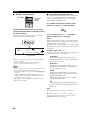
Manufactured under license from Dolby Laboratories.
“Dolby”, “Pro Logic”, “Surround EX”, and the double-D symbol
are trademarks of Dolby Laboratories.
SILENT CINEMA is a trademark of YAMAHA
CORPORATION.
“DCDi” is a trademark of Faroudja, a division of Genesis
Microchip, Inc.
“DTS”, “DTS-ES Digital Surround”, “Neo:6” and “DTS 96/24”
are trademarks of Digital Theater Systems, Inc.
“THX” and the “THX” logo are registered trademarks of THX
Ltd. “Surround EX” is a jointly developed technology of THX
and Dolby Laboratories, Inc. and is a trademark of Dolby
Laboratories, Inc. All rights reserved. Used under authorization.
“i.LINK” and the “i.LINK” logo are trademarks of Sony
Corporation.
FEATURES

GETTING STARTED
3
English
INTRODUCTION
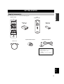
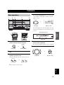
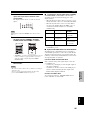
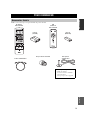
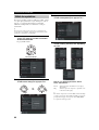
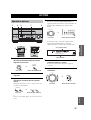
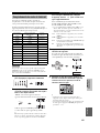
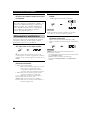
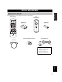
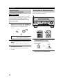
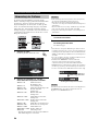
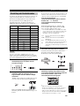
Please check that you received all of the following parts.
GETTING STARTED
Supplied accessories
TRANSMIT
RE-NAME
STANDBY
TUNER
MULTI CH IN
PURE DIRECT
TOP EXIT
INPUT MODE
SOUND
SYSTEM
CLEAR LEARN MACRO
OFF ON
MACRO
PHONO
CD
DVD
DVR
VCR 2
TITLE
MENU
CHAPTER
PAUSE
STOP
POWER
REC
STEREO
EX/ES
AMP
10KEY
JAZZ
MOVIE
THX
MUTE
VOLUME
STRAIGHT
TV INPUT
TV VOL
CH
PRESET
DISC
EFFECT
ON SCREEN
TESTSLEEP
PUSH
TV MUTE
MUSIC
ENTERTAIN
ROCK
HALL 1
HALL 2
CHURCH
NIGHT
/DTS
CHP/INDEX
A/B/C/D/E
SELECT
DISPLAY
SEARCH
SOURCE
PLAY
–+
ENTER
DTV/LD
VCR 1
CD-R
MD/TAPE
SAT
CABLE
POWER
V-AU X
1
5
9
6
0 +10
+100
78
23
4
SPEAKERS
A B
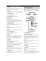
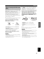
Remote control
Batteries (3)
(AA, LR6)
Power cord
Optimizer microphone
Speaker terminal wrench
Batteries (2)
(AAA, R03)
POWER
VOL
MUTE
TOP
EXIT
SYSTEM
STANDBY
+
–
ENTER
GUI
Remote control
*
The optimizer microphone is
sensitive to heat.
– Keep it away from direct
sunlight.
– Do not place it on top of this unit.

GETTING STARTED
4
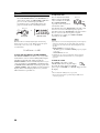
Notes on batteries
• Change all of the batteries if you notice the following conditions: the operation range of the remote control decreases, the indicator
does not flash or its light becomes dim.
• Do not use old batteries together with new ones.
• Do not use different types of batteries (such as alkaline and manganese batteries) together. Read the packaging carefully as these
different types of batteries may have the same shape and color.
• If the batteries have leaked, dispose of them immediately. Avoid touching the leaked material or letting it come into contact with
clothing, etc. Clean the battery compartment thoroughly before installing new batteries.
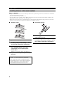
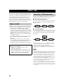
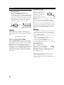
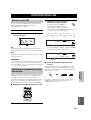
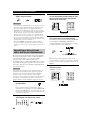
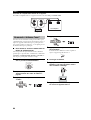
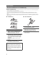
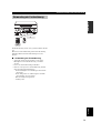
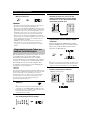
■ Remote control
1 Open the battery compartment cover.
2 Insert three supplied batteries (AA, LR6)
according to the polarity markings (+ and –)
on the inside of the battery compartment.
3 After new batteries are correctly inserted,
press the RESET button in the battery
compartment using a ball point pen or
similar object.
(This does not clear the contents of the memory.)
4 Replace the cover by pressing until it snaps
into place.
■ GUI remote control
1 Press the part and slide the battery
compartment cover off.
2 Insert two supplied batteries (AAA, R03)
according to the polarity markings (+ and –)
on the inside of the battery compartment.
3 Slide the cover back until it snaps into place.
Installing batteries in the remote controls
If the remote control is without batteries for more than
3 minutes, or if exhausted batteries remain in the
remote control, the contents of the memory may be
cleared. If the memory is cleared, insert new batteries,
set up the manufacturer code(s) and program any
acquired functions that may have been cleared.
RESET button
1
3
2

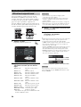
CONTROLS AND FUNCTIONS
5
English
INTRODUCTION
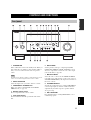
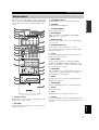
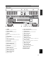
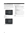
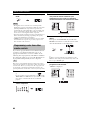
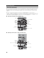
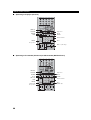
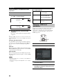
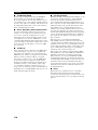
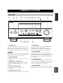
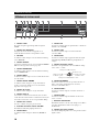
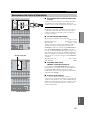
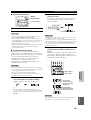
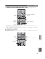
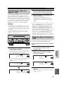
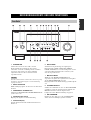
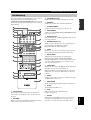
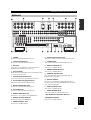
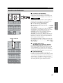
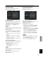
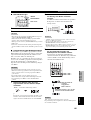
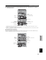
1 STANDBY/ON
Turns on this unit or sets it to the standby mode. When you
turn on this unit, you will hear a click and there will be a
delay of a few seconds before this unit can reproduce
sound.
In standby mode, this unit consumes a small amount of power in
order to receive infrared-signals from the remote controls.
2 INPUT SELECTOR
Selects the input source you want to listen to or watch.
3 PURE DIRECT 2CH/MULTI CH
Turns on or off the 2-channel/multi-channel PURE
DIRECT mode (see page 43).
4 Remote control sensor
Receives signals from the remote controls.
5 Front panel display
Shows information about the operational status of this
unit.
6 INPUT MODE
Sets the priority for the type of input signal (AUTO,
i.LINK, DTS, DIGITAL, D.D.RF, ANALOG) received
when one component is connected to two or more input
jacks on this unit (see page 44).
7 MULTI CH INPUT
Selects the source connected to the MULTI CH INPUT
jacks. This source takes priority over the source selected
with INPUT SELECTOR (or the input selector buttons on
the remote control).
8 STRAIGHT/EFFECT
Switches the sound fields off or on. When STRAIGHT is
selected, input signals (2-channel or multi-channel) are
output directly from their respective speakers without
effect processing.
9 DSP PROGRAM
Press this button before rotating MULTI JOG to select
sound field programs.
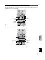
CONTROLS AND FUNCTIONS
Front panel
PHONO
DVR
PURE DIRECT
2CH/MULTI CH
SPEAKERS
VIDEO AUX
REC OUT/ZONE 2
INPUT MODE
SOURCE/REMOTE
DVDDTV/LD
MD/TAPE
CD-R
TUNER
CD
VIDEO AUX
VCR 2
VCR 1
SAT
CABLE
AB
STRAIGHT
EFFECT
MULTI CH
INPUT
DSP
PROGRAM
BALANCE
TONE
CONTROL
VOLUME
INPUT SELECTOR
MULTI JOG
SILENT OPTIMIZER
MIC
PHONES
OPTICAL
R
AUDIO
L
VIDEO
S VIDEO
STANDBY
/ON
12 54C3789AB06
EFG HD
Note

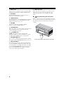
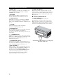
CONTROLS AND FUNCTIONS
6
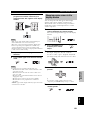
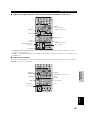
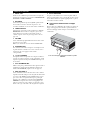
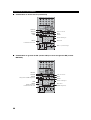
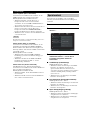
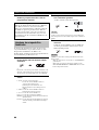
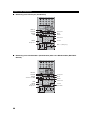
0 MULTI JOG
Rotate to select or adjust items when used with the DSP
PROGRAM, BALANCE or TONE CONTROL buttons.
A BALANCE
Adjusts the left/right balance of the front, presence,
surround and surround back speakers.
B TONE CONTROL
Press this button before rotating MULTI JOG to adjust the
bass/treble balance for the front left/right, center and
subwoofer channels (see page 38).
C VOLUME
Controls the output level of all audio channels.
This does not affect the REC OUT level.
D SPEAKERS A/B
Turns on or off the set of front speakers connected to the A
and/or B terminals on the rear panel each time the
corresponding button is pressed.
E PHONES jack
Outputs audio signals for private listening with
headphones. When you connect headphones, no signals
are output to the OUTPUT jacks or to the speakers.
F OPTIMIZER MIC jack
Use to connect and input audio signals from the supplied
microphone for the AUTO SETUP function (see page 31).
G REC OUT/ZONE 2
Selects the source you want to direct to the audio/video
recorder and ZONE 2 outputs independently of the source
you are listening to or watching in the main room. When
set to the SOURCE/REMOTE position, the input source is
directed to all outputs. The source in Zone 2 and the
source you record are always identical.
H VIDEO AUX jacks
Inputs audio and video signals from a portable external
source such as a game console. To reproduce source
signals from these jacks, select V-AUX as the input
source.
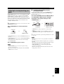
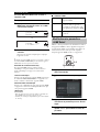
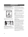
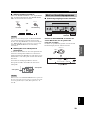
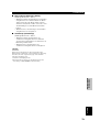
■ Opening and closing the front panel
door
When you want to use the controls behind the front panel
door, open the door by gently pressing on the lower part of
the panel. Keep the door closed when not using these
controls.
To open, press gently on the lower part of the panel.

CONTROLS AND FUNCTIONS
7
English
INTRODUCTION
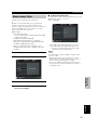
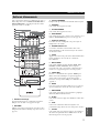
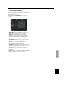
This section describes the functions of each control on the
remote control. See “REMOTE CONTROL FEATURES”
on page 80 to operate other components with this remote
control.
1 Infrared window
Outputs infrared control signals. Aim this window at the
component you want to operate.
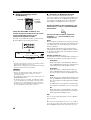
2 RE-NAME
Used for changing the input source name in the display
window (see page 83).
3 TRANSMIT indicator
Flashes while the remote control is sending signals.
4 STANDBY
Sets this unit in the standby mode.
5 SYSTEM POWER
Turns on this unit’s power.
6 PURE DIRECT
Turns on or off the 2-channel/multi-channel PURE
DIRECT mode (see page 43).
7 Display window
Shows the name of the selected source component that
you can control.
8 SOURCE SELECT k/n
Selects another component that you can control
independently of the input component selected with the
input selector buttons.
9 LIGHT
Press to momentarily light up the display window and
buttons on this remote control.
0 INPUT MODE
Sets the priority for the type of input signal (AUTO,
i.LINK, DTS, DIGITAL, D.D.RF, ANALOG) received
when one component is connected to two or more input
jacks on this unit (see page 44).
A 10KEY/AMP
Slide to 10KEY to select a numeric button or operate the
component selected using the input selector buttons.
Slide to AMP to operate this unit.
B EX/ES
Switches between 5.1- and 6.1/7.1-channel playback of
multi-channel software.
C ON SCREEN
Selects the GUI display mode for your video monitor.
D SLEEP
Sets the sleep timer.
E TEST
Outputs the test tone to adjust the speaker levels.
F CLEAR
Used for clearing functions acquired when using the learn
and rename features and setting manufacturer codes (see
page 86).
Remote control
TRANSMIT
RE-NAME
STANDBY
TUNER
MULTI CH IN
PURE DIRECT
TOP EXIT
INPUT MODE
SOUND
SYSTEM
CLEAR LEARN MACRO
OFF ON
MACRO
PHONO
CD
DVD
DVR
VCR 2
TITLE
MENU
CHAPTER
PAUSE
STOP
POWER
REC
STEREO
EX/ES
AMP
10KEY
JAZZ
MOVIE
THX
MUTE
VOLUME
STRAIGHT
TV INPUT
TV VOL
CH
PRESET
DISC
EFFECT
ON SCREEN
TESTSLEEP
PUSH
TV MUTE
MUSIC
ENTERTAIN
ROCK
HALL 1
HALL 2
CHURCH
NIGHT
/DTS
CHP/INDEX
A/B/C/D/E
SELECT
DISPLAY
SEARCH
SOURCE
PLAY
–+
ENTER
DTV/LD
VCR 1
CD-R
MD/TAPE
SAT
CABLE
POWER
V-AUX
1
5
9
6
0 +10
+100
78
23
4
SPEAKERS
A B
F
G
H
I
O
Q
P
K
S
R
t
J
1
2
3
4
5
7
8
9
C
D
E
A
B
6
L
M
N
0

CONTROLS AND FUNCTIONS
8
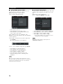
G LEARN
Used for setting up the manufacturer code or for
programming the functions of other remote controls (see
pages 81 and 82).
H MACRO
Used to program a series of operations for control by a
single button (see page 84).
I MACRO ON/OFF
Turns the macro function on and off.
J Input selector buttons
Selects the input source and changes the control area.
K MULTI CH IN
Selects the source connected to the MULTI CH INPUT
jacks. This source takes priority over the source selected
with INPUT SELECTOR (or the input selector buttons on
the remote control).
L Operation buttons
Operate various parameters and commands shown in the
on-screen display.
M EXIT
Press to exit the on-screen display menus.
N TOP
Press to display the top level of the on-screen display
menus.
O Sound field program
Use to select sound field programs.
P MUTE
Mutes the sound. The MUTE indicator turns on when the
MUTE function is on. Press again to restore the audio
output to the previous volume level.
Q VOLUME +/–
Increases or decreases the volume level.
R STRAIGHT/EFFECT
Switches the sound fields off or on. When STRAIGHT is
selected, input signals (2-channel or multi-channel) are
output directly from their respective speakers without
effect processing.
S SPEAKERS A/B
Turn on or off the set of front speakers connected to the A
and/or B terminals on the rear panel each time the
corresponding button is pressed.
T Cover
Slide down to use the concealed buttons for various setup
and parameter operations.
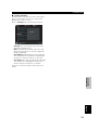
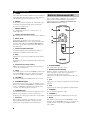
This section describes the controls and functions of the
GUI remote control. See “USING THE GUI REMOTE
CONTROL” on page 29 for details.
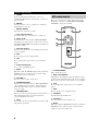
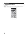
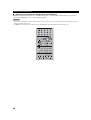
1 SYSTEM POWER
Turns on this unit’s power.
2 Multi-control/ENTER
Tilt up/down or left/right to navigate through the various
parameters and commands shown in the on-screen display.
Press to choose the selected item in the on-screen display.
3 TOP
Press to display the top level of the on-screen display
menus.
4 EXIT
Press to exit the on-screen display menus.
5 STANDBY
Sets this unit in the standby mode.
6 VOLUME +/–
Increases or decreases the volume level.
7 MUTE
Mutes the sound. The MUTE indicator turns on when the
MUTE function is on. Press again to restore the audio
output to the previous volume level.
GUI remote control
POWER
VOL
MUTE
TOP
EXIT
SYSTEM
STANDBY
+
–
ENTER
6
5
1
2
3
4
7

CONTROLS AND FUNCTIONS
9
English
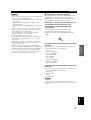
INTRODUCTION
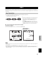
The remote controls transmit directional infrared beams.
Be sure to aim the remote controls directly at the remote
control sensor on the main unit during operation.
■ Handling the remote controls
• Do not spill water or other liquids on the remote
controls.
• Do not drop the remote controls.
• Do not leave or store the remote controls in the
following types of conditions:
– high humidity such as near a bath
– high temperature such as near a heater or stove
– extremely low temperatures
– dusty locations
Using the remote controls
PHONO
DVR
PURE DIRECT
2CH/MULTI CH
SPEAKERS
VIDEO AUX
REC OUT/ZONE 2
INPUT MODE
SOURCE/REMOTE
DVDDTV/LD
MD/TAPE
CD-R
CD
TUNER
VIDEO AUX
VCR 2
VCR 1
SAT
CABLE
AB
STRAIGHT
EFFECT
MULTI CH
INPUT
DSP
PROGRAM
BALANCE
TONE
CONTROL
VOLUME
INPUT SELECTOR
MULTI JOG
SILENT OPTIMIZER
MIC
PHONES
OPTICAL
R
AUDIO
L
VIDEO
S VIDEO
STANDBY
/ON
3030
POWER
VOL
MUTE
TOP EXIT
SYSTEM
STANDBY
+
–
ENTER
Approximately 6 m (20 ft)

CONTROLS AND FUNCTIONS
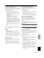
10
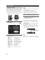
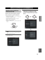
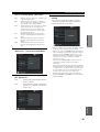
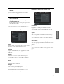
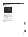
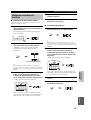
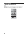
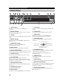
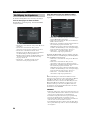
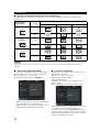
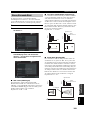
1 i.LINK indicator
Lights up when this unit is playing back i.LINK signals.
2 Decoder indicators
When any of this unit’s decoders function, the respective
indicator lights up.
3 HiFi DSP
Lights up when you select a HiFi DSP sound field
program.
4 VIRTUAL indicator
Lights up when Virtual CINEMA DSP is active (see
page 42).
5 CINEMA DSP indicator
Lights up when you select a CINEMA DSP sound field
program.
6 NIGHT indicator
Lights up when you select the night listening mode.
7 SILENT CINEMA indicator
Lights up when headphones are connected and a sound
field program selected (see page 38).
8 Headphones indicator
Lights up when headphones are connected.
9 SP A B indicators
Lights up according to the set of front speakers selected.
Both indicators light up when both sets of speakers are
selected, or when bi-wiring.
0 Input source indicators
A cursor lights to show the current input source.
A VOLUME level indicators
Indicates the volume level.
B MUTE indicator
Lights up when the MUTE function is on.
C LFE indicator
Lights up when the input signal contains the LFE signal.
D THX indicators
Lights up when a THX program is selected.
E PCM indicator
Lights up when this unit is reproducing PCM (pulse code
modulation) digital audio signals.
F Sound field indicators
Lights to indicate the active DSP sound fields.
G OPTIMIZER indicator
Lights up during the auto setup procedure and when the
auto setup speaker settings are used without any
modifications.
H ZONE 2 indicator
Lights up when Zone 2 power is on.
I SLEEP indicator
Lights up when the sleep timer is on.
J Multi-information display
Shows the current sound field program name and other
information when adjusting or changing settings.
K Input channel indicators
Indicates the channel component of the current digital
input signal.
Front panel display
MULTI CH
V–AUX DVR
VCR 1VCR 2 DTV/LDSAT CABLE DVD
MD/TAPE
CD–R
CD
TUNER
PHONO
96
24
MATRIX DISCRETE
HiFi DSP
NIGHT
SILENT
SLEEP
ZONE2
OPTIMIZER
DIGITAL
PL
PCMTHX
PL
EX
VIRTUAL
MUTE
RL
C
SL
SR
SB
VOLUME
LFE
A B
SP
C
I
315789 B40
D
6
K
A2
E
H
FJ
G
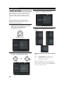
Presence DSP sound field
Listening position
Surround left
DSP sound field
Surround right
DSP sound field
Surround back DSP sound field

CONTROLS AND FUNCTIONS
11
English
INTRODUCTION
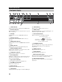
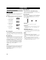
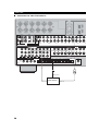
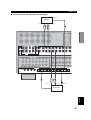
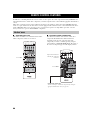
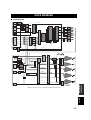
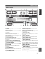
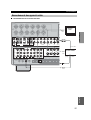
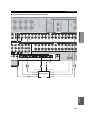
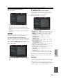
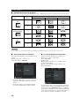
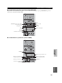
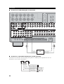
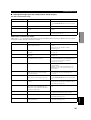
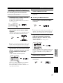
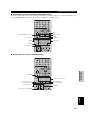
1 PHONO
See page 24 for connection information.
2 Speaker terminals
See page 14 for connection information.
3 AC INLET
Use this inlet to plug in the supplied power cable (see
page 27).
4 AC OUTLET(S)
Use to supply power to your other A/V components (see
page 27).
5 Audio component jacks
See pages 24 and 25 for connection information.
6 Pre out jacks
See page 26 for connection information.
7 MULTI CH INPUT jacks
See page 18 for connection information.
8 2CH IN jacks
See page 18 for connection information.
9 DIGITAL INPUT jacks
See pages 17, 19-21 and 23-25 for details.
0 DIGITAL OUTPUT jacks
See pages 23 and 25 for details.
A ZONE 2 COAXIAL OUT
See page 93 for details.
B Video component jacks
See pages 17 and 19-23 for connection information.
C i.LINK connectors
See pages 26 and 96 for connection information.
D ZONE 2 video jacks
See page 93 for details.
E REMOTE IN/OUT jacks
See page 93 for details.
F CONTROL OUT jacks
These are control expansion terminals for commercial use.
G RS-232C terminal
This is a control expansion terminal for commercial use.
Consult you dealer for details.
H ZONE 2 audio jacks
See page 93 for details.
I FRONT IN/CENTER IN
See page 26 for connection information.
< General models only >
VOLTAGE SELECTOR
See page 27 for details.
Rear panel
L L
R R
++
–
+
–
+
–
–
FRONT
A
FRONT
B
FRONT
B
FRONT
A
SURROUND
SUBWOOFER
FRONT
PURE DIRECT
CD DVD DTV/LD CBL SAT VCR 1
IN(PLAY)
MD/TAPE CD-R
OUT(REC) OUT(REC)
CENTERSURROUND
BACK
PRESENCE
/ZONE 2
SPEAKERS
AUDIO
SURROUND
BACK
(SINGLE)
SURROUND
SPEAKERSAC OUTLETS
AC IN
L
R
CENTER(SINGLE)
PHONO
SURROUND
BACK
SURROUND
GND
MULTI CH INPUT 2CH IN
PRESENCE
/ZONE 2
IN(PLAY) IN(PLAY) OUT(REC)
VCR 2
IN(PLAY) OUT(REC)
DVR
IN(PLAY) OUT(REC)
OUT
ZONE 2 FRONT CENTER
IN VCR 1 OUT
IN
VCR 2 OUT IN DVR OUT ZONE 2
SURROUND
BACK
PRESENCE SUBWOOFER
OUT (SINGLE)
L
R
COMPONENT VIDEO VIDEO
VIDEO
IN OUT IN +12V 15mA MAX
S.VIDEO
DVD1
–MONITOR OUT–2
DTV/LD
CBL SAT
Y
P
B
PR
DVD CBL SAT VCR1 DVRDTV/LD
1
–MONITOR OUT–2
DIGITAL INPUT
q RF—
DTV/LD DTV SATCD CD CD-R CD-R MD/TAPEDVD DVD DVR DVR
OPTICAL COAXIAL
ZONE 2CBLDVR
DIGITAL OUTPUT
1
REMOTE
CONTROL OUT
21 2
RS
–
232C
A B C D E F
1
2
4
3
5
6
7
8
9
0
BA
C
D
S400
(AUDIO)
SURROUND
S1/S2
(AC-3)
COAXIAL
LD
TUNER
2
1
3
5
2
6
4
0A CBFIGHD78 E9
(REAR)
(FRONT)
OUT
POWER AMP IN

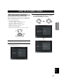
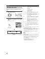
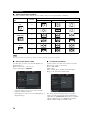
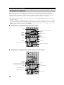
SPEAKER SETUP
12
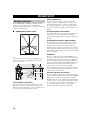
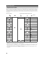
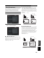
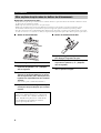
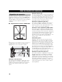
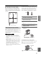
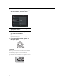
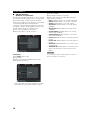
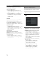
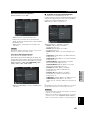
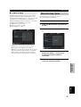
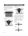
Since CINEMA DSP and THX are different surround
post-processing technologies, we recommend the
following speaker setup in order to enjoy the best surround
sound of each technology.
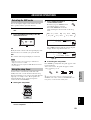
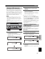
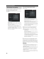
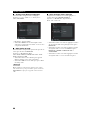
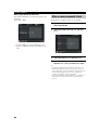
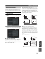
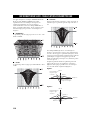
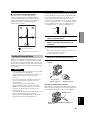
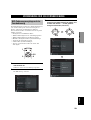
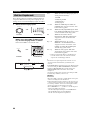
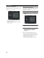
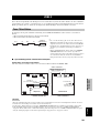
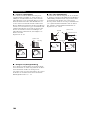
■ CINEMA DSP speaker layout
y
The speaker layout above shows the standard ITU-R speaker
setup. You can use it to enjoy CINEMA DSP, multi-channel
audio sources and THX.
Front speakers (FR and FL)
The front speakers are used for the main source sound.
Place these speakers an equal distance from the ideal
listening position. The distance of each speaker from each
side of the video monitor should be the same.
Center speaker (C)
The center speaker is for the center channel sounds
(dialog, vocals, etc.). Align the front face of the center
speaker with the front face of your video monitor. Place
the speaker centrally between the front speakers and as
close to the monitor as possible, such as directly over or
under it.
Surround speakers (SR and SL)
The surround speakers are used for effect and surround
sounds. Place these speakers behind your listening
position, facing slightly inwards, about 1.8 m (6 ft) above
the floor.
Surround back speakers (SBR and SBL)
The surround back speakers supplement the surround
speakers and provide for more realistic front-to-back
transitions. Place these speakers directly behind the
listening position and at the same height as the surround
speakers. They should be positioned at least 30 cm (12 in.)
apart. Ideally, they should be positioned at the same width
as the front speakers.
Subwoofer
The use of a subwoofer, such as the YAMAHA Active
Servo Processing Subwoofer System, is effective not only
for reinforcing bass frequencies from any or all channels,
but also for high fidelity reproduction of the LFE (low-
frequency effect) channel included in Dolby Digital and
DTS software. The position of the subwoofer is not so
critical, because low bass sounds are not highly
directional. But it is better to place the subwoofer near the
front speakers. Turn it slightly toward the center of the
room to reduce wall reflections.
Presence speakers (PR and PL)
Presence speakers supplement the sound from the front
speakers with extra ambient effects produced by CINEMA
DSP (see page 38). These effects include sounds that
filmmakers intend to locate a little farther back behind the
screen in order to create more theater-like ambience. Place
these speakers at the front of the room about 0.5 - 1 m
(1 - 3 ft) outside the front speakers, facing slightly
inwards, and about 1.8 m (6 ft) above the floor.
SPEAKER SETUP
Speaker placement
60˚
30˚
PL
PR
SBR
SBL
FL
FR
C
SL
SR
SR
80˚
SL
more than 30 cm (12 in.)
1.8 m (6 ft)
1.8 m (6 ft)

13
English
SPEAKER SETUP
PREPARATION
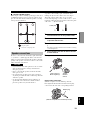
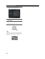
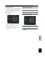
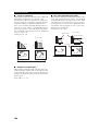
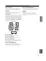
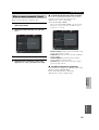
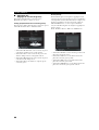
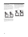
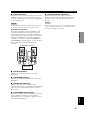
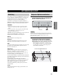
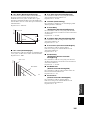
■ Di-pole speaker layout
Either di-pole or direct radiating speaker types can be used
for THX surround. If you choose di-pole speakers, please
place the surround and surround back speakers according
to the speaker layout below.
Be sure to connect the left channel (L), right channel (R),
“+” (red) and “–” (black) properly. If the connections are
faulty, no sound can be heard from the speakers, and if the
polarity of the speaker connections is incorrect, the sound
will be unnatural and lack bass.
• If you intend to use 6-ohm speakers, be sure to set this
unit’s speaker impedance setting to 6 ohms before
using (see page 28).
• Before connecting the speakers, make sure that this
unit’s power is off.
• Do not let the bare speaker wires touch each other or
any metal part of this unit. This could damage this unit
and/or the speakers.
• Use magnetically shielded speakers. If this type of
speaker still creates interference with the monitor,
place the speakers away from the monitor.
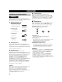
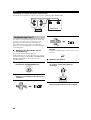
A speaker cord is actually a pair of insulated cables
running side by side. One cable is colored or shaped
differently, perhaps with a stripe, groove or ridges.
Connect the striped (grooved, etc.) cable to the “+” (red)
terminals on this unit and your speaker. Connect the plain
cable to the “–” (black) terminals.
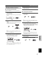
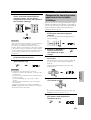
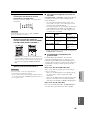
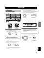
1 Remove approximately 10 mm (3/8") of
insulation from each of the speaker cables.
2 Twist the exposed wires of the cable together
to prevent short circuits.
3 Unscrew the knob.
y
The supplied speaker terminal wrench is useful for screwing
or unscrewing knobs.
4 Insert one bare wire into the hole in the side
of each terminal.
5 Tighten the knob to secure the wire.
Banana plug connections
(With the exception of U.K. and Europe models)
First, tighten the knob and then insert the banana plug
connector into the end of the corresponding terminal.
Speaker connections
FL
SR
SL
FR
C
SBR
SBL
: Di-pole speaker
: Direction of di-pole speaker
CAUTION
10 mm (3/8")
1
2
Red: positive (+)
Black: negative (–)
5
4
3
Speaker
terminal
wrench
Banana plug
(With the exception of U.K. and Europe models)

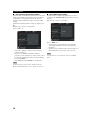
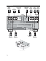
14
SPEAKER SETUP
L L
R R
++
–
+
–
+
–
–
FRONT
A
FRONT
B
FRONT
B
FRONT
A
SURROUND CENTERSURROUND
BACK
PRESENCE
/ZONE 2
SPEAKERS
SURROUND
BACK
(SINGLE)
SURROUND
SPEAKERS
PRESENCE
/ZONE 2
SUBWOOFER
R
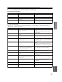
124 11
9 7
3
6 8
510
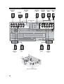
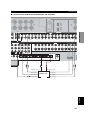
Right
subwoofer
system
Center
speaker
Front right
speaker (A)
Surround back
right speaker
Surround
right
speaker
1
2
3
4
5
6
10
11
9
8
7
Speaker layout
Presence
right
speaker
Presence
left
speaker
Surround back
left speaker
Front left
speaker (A)
Surround
left
speaker
Left
subwoofer
system
Front speakers (B)

15
English
SPEAKER SETUP
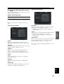
PREPARATION
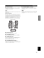
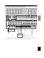
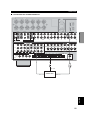
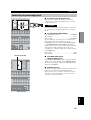
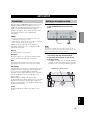
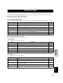
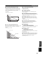
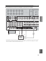
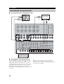
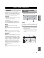
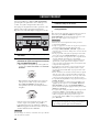
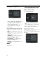
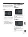
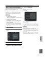
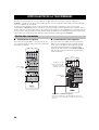
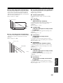
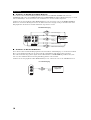
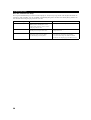
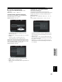
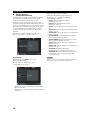
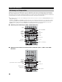
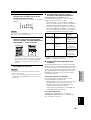
■ FRONT terminals
Connect one or two speaker systems to these terminals. If
you use only one speaker system, connect it to either of
the FRONT A or B terminals.
The Canada model cannot output to two separate speaker systems
simultaneously.
Bi-wired connection
The unit also allows you to make bi-wired connections to
one speaker system. Use two pairs of speaker cables for
each speaker (one pair for the woofer and one pair for the
tweeter/mid-range). To use the bi-wired connections, press
SPEAKERS A and SPEAKERS B on the front panel so
that both SP A and B light up on the front panel display.
■ CENTER terminals
Connect a center speaker to these terminals.
■ SURROUND terminals
Connect a surround speaker system to these terminals.
■ SUBWOOFER jacks
Connect one or two subwoofer(s) with built-in amplifier,
such as the YAMAHA Active Servo Processing
Subwoofer System, to the jack(s).
■ SURROUND BACK terminals
Connect a surround back speaker system to these
terminals. If you only connect one surround back speaker,
connect it to the left (L) terminals.
■ PRESENCE/ZONE 2 terminals
Connect presence speakers to these terminals. You can
also use these terminals for connecting Zone 2 speakers
(see page 94).
The presence speakers output ambient effects created by the DSP
sound fields. They do not output sound when other sound fields
are selected.
Note
Bi-wired connection
This unit
Note

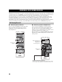
CONNECTIONS
16
Do not connect this unit or other components to the mains
power until all connections between components are
completed.
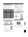
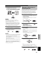
■ Signal directions and cable indications
■ Analog jacks
You can input analog signals from audio components by
connecting an audio pin cable to each of this unit’s analog
jacks. Connect red plugs to the right jacks and white plugs
to the left jacks.
■ Digital jacks
This unit has digital jacks for direct transmission of digital
signals through either coaxial or fiber optic cables. You
can use the digital jacks to input PCM, Dolby Digital and
DTS bitstreams. When you connect components to both
the COAXIAL and OPTICAL jacks, priority is given to
the input signals from the COAXIAL jack. COAXIAL
jacks are compatible with digital signals with sampling
frequencies up to 192 kHz, and OPTICAL jacks with
sampling frequencies up to 96 kHz.
This unit handles digital and analog signals independently. Thus,
audio signals input to the analog jacks are only output to the
analog OUT (REC) jacks. Likewise audio signals input to the
digital (OPTICAL or COAXIAL) jacks are only output to the
DIGITAL OUTPUT jacks.
■ i.LINK jacks
This unit can be connected with i.LINK equipped
components using 4-pin, S400 i.LINK cables. This
connection enables you to send and receive digital audio at
high speed and with high fidelity.
■ Video jacks
This unit has three types of video jacks. The signals input
through any type of VIDEO IN jack can be output through
any of the VIDEO (MONITOR OUT) jacks (automatic
video conversion).
VIDEO jack
For conventional composite video signals.
S VIDEO jack
For S video signals, separated into luminance (Y) and
color (C) video signals to achieve high-quality color
reproduction.
COMPONENT VIDEO jacks
For component signals, separated into luminance (Y)
and color difference (P
B, PR) to provide the best quality
in picture reproduction.
• When signals are input simultaneously through the
COMPONENT VIDEO, S VIDEO and VIDEO jacks, the input
priority is as follows: COMPONENT VIDEO, S VIDEO then
VIDEO.
• Video signal conversion is only possible for signals input
through the COMPONENT VIDEO jack when Resolution is set
to 480i/576i. Signals will not be converted when Resolution is
set to 480p/576p, 720p or 1080i (see page 72).
CONNECTIONS
Connecting components
Note
CAUTION
S
O
V
L
R
V
C
video signal direction
left analog cables
right analog cables
optical cables
coaxial cables
video cables
S video cables
For analog signals
For digital signals
For video signals
audio signal direction
Notes
VIDEO
S VIDEO
COMPONENT VIDEO
P
R
P
B
Y

17
English
CONNECTIONS
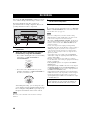
PREPARATION
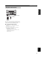
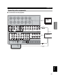
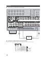
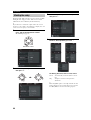
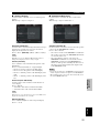
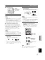
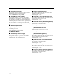
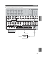
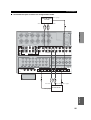
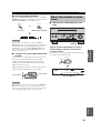
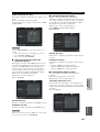
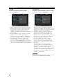
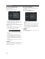
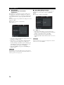
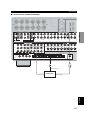
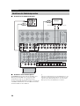
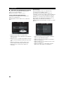
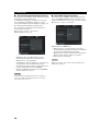
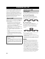
■ Connections for DVD playback
Connecting video components
R R
++
–
–
FRONT
A
FRONT
B
SURROUND
SUBWOOFER
FRONT
PURE DIRECT
CD DVD DTV/LD
IN(PLAY)
MD/TAPE CD-R
OUT(REC) OUT(REC)
CENTERSURROUND
BACK
PRESENCE
/ZONE 2
SPEAKERS
AC I
L
R
CENTER(SINGLE)
PHONO
TUNER
SURROUND
BACK
SURROUND
GND
MULTI CH INPUT 2CH IN
IN(PLAY)
COMPONENT VIDEO
DVD1
–MONITOR OUT–2
DTV/LD
Y
P
B
PR
DVD CBL SAT VCR1 DVRDTV/LD
1
–MONITOR OUT–2
DIGITAL INPUT
q RF—
DTV/LD DTV SATCD CD CD-R CD-R MD/TDVD DVD DVRCBLDVR
A B C D E F
1
2
4
3
5
6
7
8
90 BA
S1/S2
(AC-3)
COAXIAL
LD
L
C
R
O
DVD player
Video
monitor
Optical out
Video out
Audio out
Video in
Coaxial out

18
CONNECTIONS
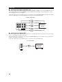
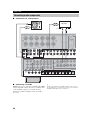
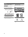
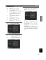
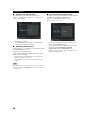
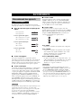
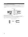
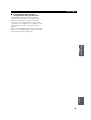
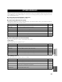
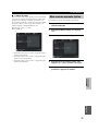
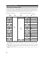
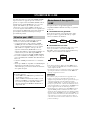
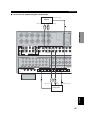
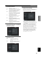
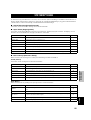
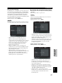
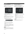
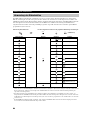
■ Connecting to the MULTI CH INPUT jacks
This unit is equipped with 8 additional input jacks (left and right FRONT, CENTER, left and right SURROUND, left and
right SURROUND BACK and SUBWOOFER) for discrete multi-channel input from a universal disc player, external
decoder, sound processor or pre-amplifier.
Connect the output jacks on your multi-disc player or external decoder to the MULTI CH INPUT jacks. Be sure to match
the left and right outputs to the left and right input jacks for the front and surround channels.
■ Connecting to the 2CH IN jacks
This unit is equipped with 2 additional input jacks for discrete 2-channel input from a universal disc player, passive input
selector or other high-speed audio component.
The signals input to these jacks can be chosen by pressing PURE DIRECT (see page 43). This feature provides the best
possible sound quality from this unit.
Connect the output jacks on your multi-disc player or external decoder to the 2CH IN jacks.
SUBWOOFER
FRONT
CENTER(SINGLE)
SURROUND
BACK
SURROUND
MULTI CH INPUT
L
R
L
R
L
R
Universal disc
player/External
decoder
For multi-channel input
Front out
Surround back out
Subwoofer out
Center out
Surround out
PURE DIRECT
2CH IN
L
R
Universal disc
player, etc.
For 2-channel input
2CH out
Pagina se încarcă ...
Pagina se încarcă ...
Pagina se încarcă ...
Pagina se încarcă ...
Pagina se încarcă ...
Pagina se încarcă ...
Pagina se încarcă ...
Pagina se încarcă ...
Pagina se încarcă ...
Pagina se încarcă ...
Pagina se încarcă ...
Pagina se încarcă ...
Pagina se încarcă ...
Pagina se încarcă ...
Pagina se încarcă ...
Pagina se încarcă ...
Pagina se încarcă ...
Pagina se încarcă ...
Pagina se încarcă ...
Pagina se încarcă ...
Pagina se încarcă ...
Pagina se încarcă ...
Pagina se încarcă ...
Pagina se încarcă ...
Pagina se încarcă ...
Pagina se încarcă ...
Pagina se încarcă ...
Pagina se încarcă ...
Pagina se încarcă ...
Pagina se încarcă ...
Pagina se încarcă ...
Pagina se încarcă ...
Pagina se încarcă ...
Pagina se încarcă ...
Pagina se încarcă ...
Pagina se încarcă ...
Pagina se încarcă ...
Pagina se încarcă ...
Pagina se încarcă ...
Pagina se încarcă ...
Pagina se încarcă ...
Pagina se încarcă ...
Pagina se încarcă ...
Pagina se încarcă ...
Pagina se încarcă ...
Pagina se încarcă ...
Pagina se încarcă ...
Pagina se încarcă ...
Pagina se încarcă ...
Pagina se încarcă ...
Pagina se încarcă ...
Pagina se încarcă ...
Pagina se încarcă ...
Pagina se încarcă ...
Pagina se încarcă ...
Pagina se încarcă ...
Pagina se încarcă ...
Pagina se încarcă ...
Pagina se încarcă ...
Pagina se încarcă ...
Pagina se încarcă ...
Pagina se încarcă ...
Pagina se încarcă ...
Pagina se încarcă ...
Pagina se încarcă ...
Pagina se încarcă ...
Pagina se încarcă ...
Pagina se încarcă ...
Pagina se încarcă ...
Pagina se încarcă ...
Pagina se încarcă ...
Pagina se încarcă ...
Pagina se încarcă ...
Pagina se încarcă ...
Pagina se încarcă ...
Pagina se încarcă ...
Pagina se încarcă ...
Pagina se încarcă ...
Pagina se încarcă ...
Pagina se încarcă ...
Pagina se încarcă ...
Pagina se încarcă ...
Pagina se încarcă ...
Pagina se încarcă ...
Pagina se încarcă ...
Pagina se încarcă ...
Pagina se încarcă ...
Pagina se încarcă ...
Pagina se încarcă ...
Pagina se încarcă ...
Pagina se încarcă ...
Pagina se încarcă ...
Pagina se încarcă ...
Pagina se încarcă ...
Pagina se încarcă ...
Pagina se încarcă ...
Pagina se încarcă ...
Pagina se încarcă ...
Pagina se încarcă ...
Pagina se încarcă ...
Pagina se încarcă ...
Pagina se încarcă ...
Pagina se încarcă ...
Pagina se încarcă ...
Pagina se încarcă ...
Pagina se încarcă ...
Pagina se încarcă ...
Pagina se încarcă ...
Pagina se încarcă ...
Pagina se încarcă ...
Pagina se încarcă ...
Pagina se încarcă ...
Pagina se încarcă ...
Pagina se încarcă ...
Pagina se încarcă ...
Pagina se încarcă ...
Pagina se încarcă ...
Pagina se încarcă ...
Pagina se încarcă ...
Pagina se încarcă ...
Pagina se încarcă ...
Pagina se încarcă ...
Pagina se încarcă ...
Pagina se încarcă ...
Pagina se încarcă ...
Pagina se încarcă ...
Pagina se încarcă ...
Pagina se încarcă ...
Pagina se încarcă ...
Pagina se încarcă ...
Pagina se încarcă ...
Pagina se încarcă ...
Pagina se încarcă ...
Pagina se încarcă ...
Pagina se încarcă ...
Pagina se încarcă ...
Pagina se încarcă ...
Pagina se încarcă ...
Pagina se încarcă ...
Pagina se încarcă ...
Pagina se încarcă ...
Pagina se încarcă ...
Pagina se încarcă ...
Pagina se încarcă ...
Pagina se încarcă ...
Pagina se încarcă ...
Pagina se încarcă ...
Pagina se încarcă ...
Pagina se încarcă ...
Pagina se încarcă ...
Pagina se încarcă ...
Pagina se încarcă ...
Pagina se încarcă ...
Pagina se încarcă ...
Pagina se încarcă ...
Pagina se încarcă ...
Pagina se încarcă ...
Pagina se încarcă ...
Pagina se încarcă ...
Pagina se încarcă ...
Pagina se încarcă ...
Pagina se încarcă ...
Pagina se încarcă ...
Pagina se încarcă ...
Pagina se încarcă ...
Pagina se încarcă ...
Pagina se încarcă ...
Pagina se încarcă ...
Pagina se încarcă ...
Pagina se încarcă ...
Pagina se încarcă ...
Pagina se încarcă ...
Pagina se încarcă ...
Pagina se încarcă ...
Pagina se încarcă ...
Pagina se încarcă ...
Pagina se încarcă ...
Pagina se încarcă ...
Pagina se încarcă ...
Pagina se încarcă ...
Pagina se încarcă ...
Pagina se încarcă ...
Pagina se încarcă ...
Pagina se încarcă ...
Pagina se încarcă ...
Pagina se încarcă ...
Pagina se încarcă ...
Pagina se încarcă ...
Pagina se încarcă ...
Pagina se încarcă ...
Pagina se încarcă ...
Pagina se încarcă ...
Pagina se încarcă ...
Pagina se încarcă ...
Pagina se încarcă ...
Pagina se încarcă ...
Pagina se încarcă ...
Pagina se încarcă ...
Pagina se încarcă ...
Pagina se încarcă ...
Pagina se încarcă ...
Pagina se încarcă ...
Pagina se încarcă ...
Pagina se încarcă ...
Pagina se încarcă ...
Pagina se încarcă ...
Pagina se încarcă ...
Pagina se încarcă ...
Pagina se încarcă ...
Pagina se încarcă ...
Pagina se încarcă ...
Pagina se încarcă ...
Pagina se încarcă ...
Pagina se încarcă ...
Pagina se încarcă ...
Pagina se încarcă ...
Pagina se încarcă ...
Pagina se încarcă ...
Pagina se încarcă ...
Pagina se încarcă ...
Pagina se încarcă ...
Pagina se încarcă ...
Pagina se încarcă ...
Pagina se încarcă ...
Pagina se încarcă ...
Pagina se încarcă ...
Pagina se încarcă ...
Pagina se încarcă ...
Pagina se încarcă ...
Pagina se încarcă ...
Pagina se încarcă ...
Pagina se încarcă ...
Pagina se încarcă ...
Pagina se încarcă ...
Pagina se încarcă ...
Pagina se încarcă ...
Pagina se încarcă ...
Pagina se încarcă ...
Pagina se încarcă ...
Pagina se încarcă ...
Pagina se încarcă ...
Pagina se încarcă ...
Pagina se încarcă ...
Pagina se încarcă ...
Pagina se încarcă ...
Pagina se încarcă ...
Pagina se încarcă ...
Pagina se încarcă ...
Pagina se încarcă ...
Pagina se încarcă ...
Pagina se încarcă ...
Pagina se încarcă ...
Pagina se încarcă ...
Pagina se încarcă ...
Pagina se încarcă ...
Pagina se încarcă ...
Pagina se încarcă ...
Pagina se încarcă ...
Pagina se încarcă ...
Pagina se încarcă ...
Pagina se încarcă ...
Pagina se încarcă ...
Pagina se încarcă ...
Pagina se încarcă ...
Pagina se încarcă ...
Pagina se încarcă ...
Pagina se încarcă ...
Pagina se încarcă ...
Pagina se încarcă ...
Pagina se încarcă ...
Pagina se încarcă ...
Pagina se încarcă ...
Pagina se încarcă ...
Pagina se încarcă ...
Pagina se încarcă ...
Pagina se încarcă ...
Pagina se încarcă ...
Pagina se încarcă ...
Pagina se încarcă ...
Pagina se încarcă ...
Pagina se încarcă ...
Pagina se încarcă ...
Pagina se încarcă ...
Pagina se încarcă ...
Pagina se încarcă ...
Pagina se încarcă ...
Pagina se încarcă ...
Pagina se încarcă ...
Pagina se încarcă ...
Pagina se încarcă ...
Pagina se încarcă ...
Pagina se încarcă ...
Pagina se încarcă ...
Pagina se încarcă ...
Pagina se încarcă ...
Pagina se încarcă ...
Pagina se încarcă ...
Pagina se încarcă ...
Pagina se încarcă ...
Pagina se încarcă ...
Pagina se încarcă ...
Pagina se încarcă ...
Pagina se încarcă ...
Pagina se încarcă ...
Pagina se încarcă ...
Pagina se încarcă ...
Pagina se încarcă ...
Pagina se încarcă ...
Pagina se încarcă ...
Pagina se încarcă ...
Pagina se încarcă ...
Pagina se încarcă ...
Pagina se încarcă ...
Pagina se încarcă ...
Pagina se încarcă ...
Pagina se încarcă ...
Pagina se încarcă ...
Pagina se încarcă ...
Pagina se încarcă ...
Pagina se încarcă ...
Pagina se încarcă ...
Pagina se încarcă ...
Pagina se încarcă ...
Pagina se încarcă ...
Pagina se încarcă ...
Pagina se încarcă ...
Pagina se încarcă ...
Pagina se încarcă ...
Pagina se încarcă ...
Pagina se încarcă ...
Pagina se încarcă ...
Pagina se încarcă ...
Pagina se încarcă ...
Pagina se încarcă ...
Pagina se încarcă ...
Pagina se încarcă ...
Pagina se încarcă ...
Pagina se încarcă ...
Pagina se încarcă ...
Pagina se încarcă ...
Pagina se încarcă ...
Pagina se încarcă ...
-
 1
1
-
 2
2
-
 3
3
-
 4
4
-
 5
5
-
 6
6
-
 7
7
-
 8
8
-
 9
9
-
 10
10
-
 11
11
-
 12
12
-
 13
13
-
 14
14
-
 15
15
-
 16
16
-
 17
17
-
 18
18
-
 19
19
-
 20
20
-
 21
21
-
 22
22
-
 23
23
-
 24
24
-
 25
25
-
 26
26
-
 27
27
-
 28
28
-
 29
29
-
 30
30
-
 31
31
-
 32
32
-
 33
33
-
 34
34
-
 35
35
-
 36
36
-
 37
37
-
 38
38
-
 39
39
-
 40
40
-
 41
41
-
 42
42
-
 43
43
-
 44
44
-
 45
45
-
 46
46
-
 47
47
-
 48
48
-
 49
49
-
 50
50
-
 51
51
-
 52
52
-
 53
53
-
 54
54
-
 55
55
-
 56
56
-
 57
57
-
 58
58
-
 59
59
-
 60
60
-
 61
61
-
 62
62
-
 63
63
-
 64
64
-
 65
65
-
 66
66
-
 67
67
-
 68
68
-
 69
69
-
 70
70
-
 71
71
-
 72
72
-
 73
73
-
 74
74
-
 75
75
-
 76
76
-
 77
77
-
 78
78
-
 79
79
-
 80
80
-
 81
81
-
 82
82
-
 83
83
-
 84
84
-
 85
85
-
 86
86
-
 87
87
-
 88
88
-
 89
89
-
 90
90
-
 91
91
-
 92
92
-
 93
93
-
 94
94
-
 95
95
-
 96
96
-
 97
97
-
 98
98
-
 99
99
-
 100
100
-
 101
101
-
 102
102
-
 103
103
-
 104
104
-
 105
105
-
 106
106
-
 107
107
-
 108
108
-
 109
109
-
 110
110
-
 111
111
-
 112
112
-
 113
113
-
 114
114
-
 115
115
-
 116
116
-
 117
117
-
 118
118
-
 119
119
-
 120
120
-
 121
121
-
 122
122
-
 123
123
-
 124
124
-
 125
125
-
 126
126
-
 127
127
-
 128
128
-
 129
129
-
 130
130
-
 131
131
-
 132
132
-
 133
133
-
 134
134
-
 135
135
-
 136
136
-
 137
137
-
 138
138
-
 139
139
-
 140
140
-
 141
141
-
 142
142
-
 143
143
-
 144
144
-
 145
145
-
 146
146
-
 147
147
-
 148
148
-
 149
149
-
 150
150
-
 151
151
-
 152
152
-
 153
153
-
 154
154
-
 155
155
-
 156
156
-
 157
157
-
 158
158
-
 159
159
-
 160
160
-
 161
161
-
 162
162
-
 163
163
-
 164
164
-
 165
165
-
 166
166
-
 167
167
-
 168
168
-
 169
169
-
 170
170
-
 171
171
-
 172
172
-
 173
173
-
 174
174
-
 175
175
-
 176
176
-
 177
177
-
 178
178
-
 179
179
-
 180
180
-
 181
181
-
 182
182
-
 183
183
-
 184
184
-
 185
185
-
 186
186
-
 187
187
-
 188
188
-
 189
189
-
 190
190
-
 191
191
-
 192
192
-
 193
193
-
 194
194
-
 195
195
-
 196
196
-
 197
197
-
 198
198
-
 199
199
-
 200
200
-
 201
201
-
 202
202
-
 203
203
-
 204
204
-
 205
205
-
 206
206
-
 207
207
-
 208
208
-
 209
209
-
 210
210
-
 211
211
-
 212
212
-
 213
213
-
 214
214
-
 215
215
-
 216
216
-
 217
217
-
 218
218
-
 219
219
-
 220
220
-
 221
221
-
 222
222
-
 223
223
-
 224
224
-
 225
225
-
 226
226
-
 227
227
-
 228
228
-
 229
229
-
 230
230
-
 231
231
-
 232
232
-
 233
233
-
 234
234
-
 235
235
-
 236
236
-
 237
237
-
 238
238
-
 239
239
-
 240
240
-
 241
241
-
 242
242
-
 243
243
-
 244
244
-
 245
245
-
 246
246
-
 247
247
-
 248
248
-
 249
249
-
 250
250
-
 251
251
-
 252
252
-
 253
253
-
 254
254
-
 255
255
-
 256
256
-
 257
257
-
 258
258
-
 259
259
-
 260
260
-
 261
261
-
 262
262
-
 263
263
-
 264
264
-
 265
265
-
 266
266
-
 267
267
-
 268
268
-
 269
269
-
 270
270
-
 271
271
-
 272
272
-
 273
273
-
 274
274
-
 275
275
-
 276
276
-
 277
277
-
 278
278
-
 279
279
-
 280
280
-
 281
281
-
 282
282
-
 283
283
-
 284
284
-
 285
285
-
 286
286
-
 287
287
-
 288
288
-
 289
289
-
 290
290
-
 291
291
-
 292
292
-
 293
293
-
 294
294
-
 295
295
-
 296
296
-
 297
297
-
 298
298
-
 299
299
-
 300
300
-
 301
301
-
 302
302
-
 303
303
-
 304
304
-
 305
305
-
 306
306
-
 307
307
-
 308
308
-
 309
309
-
 310
310
-
 311
311
-
 312
312
-
 313
313
-
 314
314
-
 315
315
-
 316
316
-
 317
317
-
 318
318
-
 319
319
-
 320
320
-
 321
321
-
 322
322
-
 323
323
-
 324
324
-
 325
325
-
 326
326
-
 327
327
-
 328
328
-
 329
329
-
 330
330
-
 331
331
-
 332
332
-
 333
333
-
 334
334
-
 335
335
-
 336
336
-
 337
337
-
 338
338
-
 339
339
-
 340
340
-
 341
341
-
 342
342
-
 343
343
-
 344
344
-
 345
345
-
 346
346
-
 347
347
-
 348
348
-
 349
349
-
 350
350
-
 351
351
-
 352
352
-
 353
353
-
 354
354
-
 355
355
-
 356
356
-
 357
357
-
 358
358
-
 359
359
-
 360
360
-
 361
361
-
 362
362


Yamaha DSP-Z9 Manualul proprietarului
- Categorie
- Receptoare AV
- Tip
- Manualul proprietarului
în alte limbi
- Türkçe: Yamaha DSP-Z9 El kitabı
- français: Yamaha DSP-Z9 Le manuel du propriétaire
- English: Yamaha DSP-Z9 Owner's manual
- Deutsch: Yamaha DSP-Z9 Bedienungsanleitung
- italiano: Yamaha DSP-Z9 Manuale del proprietario
- svenska: Yamaha DSP-Z9 Bruksanvisning
- dansk: Yamaha DSP-Z9 Brugervejledning
- Nederlands: Yamaha DSP-Z9 de handleiding
Lucrări conexe
-
Yamaha RX-V4600 Manualul proprietarului
-
-
-
-
Yamaha DSP-Z11 Manual de utilizare
-
Yamaha RX V3900 - AV Network Receiver Manual de utilizare
-
Yamaha RX-V3800 Manualul proprietarului
-
-
-
Yamaha DVR-S200 Manualul proprietarului
