Makita RP1800 Manual de utilizare
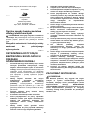
- Categorie
- Unelte electrice
- Tip
- Manual de utilizare

1
GB Router INSTRUCTION MANUAL
UA Фрезер ІНСТРУКЦІЯ З ЕКСПЛУАТАЦІЇ
PL Frezarka górnowrzecionowa INSTRUKCJA OBSŁUGI
RO Maşină de frezat verticală MANUAL DE INSTRUCŢIUNI
DE Oberfräse BEDIENUNGSANLEITUNG
HU Felsőmaró HASZNÁLATI KÉZIKÖNYV
SK Horná fréza NÁVOD NA OBSLUHU
CZ Horní frézka NÁVOD K OBSLUZE
RP1800
RP1800F
RP1801
RP1801F
RP2300FC
RP2301FC

2
1
2
3
4
5
6
7
8
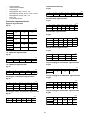
1 009857
1
2 009855
1
2
3
3 009858
1
2
4 009864
1
5 009865
1
6 009866
12
7 009854 8 009860
1
23
4
9 001985
1
2
3
4
5
10 009859 11 009860
12
55 mm
55 mm
3
12 004931
13 009861 14 009874
1
15 009873

3
1
2
16 009872
1
d
17 009871
2
18 009870
19 009862
1
2
20 009863
1
2
3
45
6
7
21 003695
22 009867
1
2
345
6
23 009868
3
1
2
24 003701
25 009877
1
2
26 009934
1
2
27 009935
1
28 009929
1
2
29 009930
1
30 009932

4
1
31 009933
1
32 009931
1
33 001145
1
2
34 009869 35 005116
R
36 005117
37 005118 38 005120 39 005121
40 005123 41 005125 42 005126
43 005129 44 005130 45 005131

5
46 005132 47 005133 48 005134
49 005135

6
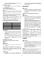
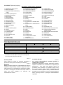
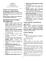
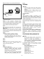
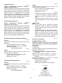
ENGLISH (Original instructions)
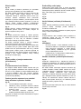
Explanation of general view
1-1. Adjusting knob
1-2. Lock lever
1-3. Stopper pole setting nut
1-4. Fast-feed button
1-5. Adjusting bolt
1-6. Stopper block
1-7. Depth pointer
1-8. Stopper pole
2-1. Nylon nut
3-1. Stopper pole
3-2. Adjusting bolt
3-3. Stopper block
4-1. Lock button
4-2. Switch trigger
5-1. Speed adjusting dial
6-1. Lamp
7-1. Shaft lock
7-2. Wrench
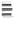
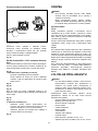
9-1. Feed direction
9-2. Bit revolving direction
9-3. Workpiece
9-4. Straight guide
10-1. Straight guide
10-2. Fine adjusting screw
10-3. Clamping screw (B)
10-4. Clamping screw (A)
10-5. Guide holder
12-1. More than 15 mm
12-2. Straight guide
12-3. Wood
15-1. Adjusting screw
16-1. Screws
16-2. Movable
17-1. When set to minimum opening
width
18-1. When set to maximum opening
width
20-1. Template guide
20-2. Lock plate
21-1. Bit
21-2. Base
21-3. Templet
21-4. Workpiece
21-5. Distance (X)
21-6. Outside diameter of the templet
guide
21-7. Templet guide
23-1. Guide holder
23-2. Adjusting screw
23-3. Clamping screw (B)
23-4. Clamping screw (C)
23-5. Trimmer guide
23-6. Clamping screw (A)
24-1. Bit
24-2. Guide roller
24-3. Workpiece
26-1. Flat washer 6
26-2. Screw M6x135
27-1. Flat washer 6
27-2. Screw M6x135
28-1. Hole
29-1. Screw M6x135
29-2. Threaded part in the motor bracket
30-1. Inside of the screw hole in the tool
base
31-1. Threaded part in the motor bracket
32-1. Screwdriver
33-1. Limit mark
34-1. Brush holder cap
34-2. Screwdriver
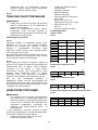
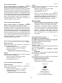
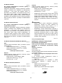
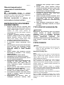
SPECIFICATIONS
Model
RP1800/RP1800F RP1801/RP1801F
RP2300FC RP2301FC
Collet chuck capacity 12 mm or 1/2"
Plunge capacity 0 - 70 mm
No load speed (min-1) 22,000 9,000 - 22,000
Overall length 312 mm
Net weight 6.0 kg 6.1 kg
Safety class /II
• Due to our continuing programme of research and development, the specifications herein are subject to change without notice.
• Note: Specifications may differ from country to country.
• Weight according to EPTA-Procedure 01/2003
ENE010-1
Intended use
The tool is intended for flush trimming and profiling of
wood, plastic and similar materials.
ENF002-1
Power supply
The tool should be connected only to a power supply of
the same voltage as indicated on the nameplate, and can
only be operated on single-phase AC supply. They are
double-insulated in accordance with European Standard
and can, therefore, also be used from sockets without
earth wire.
For Model RP1800
ENF100-1
For public low-voltage distribution systems of
between 220 V and 250 V.
Switching operations of electric apparatus cause voltage
fluctuations. The operation of this device under
unfavorable mains conditions can have adverse effects
to the operation of other equipment. With a mains
impedance equal or less than 0.40 Ohms it can be
presumed that there will be no negative effects. The
mains socket used for this device must be protected with
a fuse or protective circuit breaker having slow tripping
characteristics.

7
For Model RP1800F
ENF100-1
For public low-voltage distribution systems of
between 220 V and 250 V.
Switching operations of electric apparatus cause voltage
fluctuations. The operation of this device under
unfavorable mains conditions can have adverse effects
to the operation of other equipment. With a mains
impedance equal or less than 0.39 Ohms it can be
presumed that there will be no negative effects. The
mains socket used for this device must be protected with
a fuse or protective circuit breaker having slow tripping
characteristics.
For Model RP1801,RP1801F
ENF100-1
For public low-voltage distribution systems of
between 220 V and 250 V.
Switching operations of electric apparatus cause voltage
fluctuations. The operation of this device under
unfavorable mains conditions can have adverse effects
to the operation of other equipment. With a mains
impedance equal or less than 0.38 Ohms it can be
presumed that there will be no negative effects. The
mains socket used for this device must be protected with
a fuse or protective circuit breaker having slow tripping
characteristics.
For Model RP1800,RP1800F,RP1801,RP1801F
ENG102-3
Noise
The typical A-weighted noise level determined according
to EN60745:
Sound pressure level (LpA) : 86 dB(A)
Sound power level (LWA) : 97 dB(A)
Uncertainty (K) : 3 dB(A)
Wear ear protection
ENG223-2
Vibration
The vibration total value (tri-axial vector sum) determined
according to EN60745:
Work mode : cutting grooves in MDF
Vibration emission (ah) : 4.0 m/s2
Uncertainty (K) : 1.5 m/s2
For Model RP2300FC,RP2301FC
ENG102-3
Noise
The typical A-weighted noise level determined according
to EN60745:
Sound pressure level (LpA) : 87 dB(A)
Sound power level (LWA) : 98 dB(A)
Uncertainty (K) : 3 dB(A)
Wear ear protection
ENG223-2
Vibration
The vibration total value (tri-axial vector sum) determined
according to EN60745:
Work mode : cutting grooves in MDF
Vibration emission (ah) : 4.5 m/s2
Uncertainty (K) : 1.5 m/s2
ENG901-1
• The declared vibration emission value has been
measured in accordance with the standard test
method and may be used for comparing one tool
with another.
• The declared vibration emission value may also be
used in a preliminary assessment of exposure.
WARNING:
• The vibration emission during actual use of the
power tool can differ from the declared emission
value depending on the ways in which the tool is
used.
• Be sure to identify safety measures to protect the
operator that are based on an estimation of
exposure in the actual conditions of use (taking
account of all parts of the operating cycle such as
the times when the tool is switched off and when it
is running idle in addition to the trigger time).
ENH101-15
For European countries only
EC Declaration of Conformity
We Makita Corporation as the responsible
manufacturer declare that the following Makita
machine(s):
Designation of Machine:
Router
Model No./ Type:
RP1800,RP1800F,RP1801,RP1801F,RP2300FC,RP2301FC
are of series production and
Conforms to the following European Directives:
2006/42/EC
And are manufactured in accordance with the following
standards or standardised documents:
EN60745
The technical documentation is kept by our authorised
representative in Europe who is:
Makita International Europe Ltd.
Michigan Drive, Tongwell,
Milton Keynes, Bucks MK15 8JD, England
26.10.2010
000230
Tomoyasu Kato
Director
Makita Corporation
3-11-8, Sumiyoshi-cho,
Anjo, Aichi, 446-8502, JAPAN

8
GEA010-1
General Power Tool Safety
Warnings
WARNING Read all safety warnings and all
instructions. Failure to follow the warnings and
instructions may result in electric shock, fire and/or
serious injury.
Save all warnings and instructions for
future reference.
GEB018-3
ROUTER SAFETY WARNINGS
1. Hold power tool by insulated gripping
surfaces, because the cutter may contact its
own cord. Cutting a "live" wire may make
exposed metal parts of the power tool "live" and
shock the operator.
2. Use clamps or another practical way to secure
and support the workpiece to a stable platform.
Holding the work by your hand or against the body
leaves it unstable and may lead to loss of control.
3. Wear hearing protection during extended
period of operation.
4. Handle the bits very carefully.
5. Check the bit carefully for cracks or damage
before operation. Replace cracked or
damaged bit immediately.
6. Avoid cutting nails. Inspect for and remove all
nails from the workpiece before operation.
7. Hold the tool firmly with both hands.
8. Keep hands away from rotating parts.
9. Make sure the bit is not contacting the
workpiece before the switch is turned on.
10. Before using the tool on an actual workpiece,
let it run for a while. Watch for vibration or
wobbling that could indicate improperly
installed bit.
11. Be careful of the bit rotating direction and the
feed direction.
12. Do not leave the tool running. Operate the tool
only when hand-held.
13. Always switch off and wait for the bit to come
to a complete stop before removing the tool
from workpiece.
14. Do not touch the bit immediately after
operation; it may be extremely hot and could
burn your skin.
15. Do not smear the tool base carelessly with
thinner, gasoline, oil or the like. They may
cause cracks in the tool base.
16. Draw attention to the need to use cutters of
the correct shank diameter and which are
suitable for the speed of the tool.
17. Some material contains chemicals which may
be toxic. Take caution to prevent dust
inhalation and skin contact. Follow material
supplier safety data.
18. Always use the correct dust mask/respirator
for the material and application you are
working with.
SAVE THESE INSTRUCTIONS.
WARNING:
DO NOT let comfort or familiarity with product
(gained from repeated use) replace strict adherence
to safety rules for the subject product. MISUSE or
failure to follow the safety rules stated in this
instruction manual may cause serious personal
injury.
FUNCTIONAL DESCRIPTION
CAUTION:
• Always be sure that the tool is switched off and
unplugged before adjusting or checking function on
the tool.
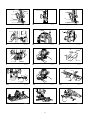
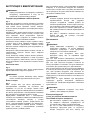
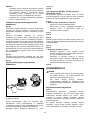
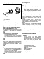
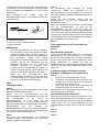
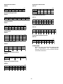
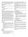
Adjusting the depth of cut
Fig.1
Place the tool on a flat surface. Loosen the lock lever and
lower the tool body until the bit just touches the flat
surface. Tighten the lock lever to lock the tool body.
Turn the stopper pole setting nut counterclockwise.
Lower the stopper pole until it makes contact with the
adjusting bolt. Align the depth pointer with the "0"
graduation. The depth of cut is indicated on the scale by
the depth pointer.
While pressing the fast-feed button, raise the stopper
pole until the desired depth of cut is obtained. Minute
depth adjustments can be obtained by turning the
adjusting knob (1 mm per turn).
By turning the stopper pole setting nut clockwise, you
can fasten the stopper pole firmly.
Now, your predetermined depth of cut can be obtained by
loosening the lock lever and then lowering the tool body
until the stopper pole makes contact with the adjusting
hex bolt of the stopper block.
Nylon nut
Fig.2
The upper limit of the tool body can be adjusted by
turning the nylon nut.
CAUTION:
• Do not lower the nylon nut too low. The bit will
protrude dangerously.

9
Stopper block
Fig.3
The stopper block has three adjusting hex bolts which
raise or lower 0.8 mm per turn. You can easily obtain
three different depths of cut using these adjusting hex
bolts without readjusting the stopper pole.
Adjust the lowest hex bolt to obtain the deepest depth of
cut, following the method of "Adjusting depth of cut".
Adjust the two remaining hex bolts to obtain shallower
depths of cut. The differences in height of these hex bolts
are equal to the differences in depths of cut.
To adjust the hex bolts, turn the hex bolts with a
screwdriver or wrench. The stopper block is also
convenient for making three passes with progressively
deeper bit settings when cutting deep grooves.
CAUTION:
• Since excessive cutting may cause overload of the
motor or difficulty in controlling the tool, the depth of
cut should not be more than 15 mm at a pass when
cutting grooves with an 8 mm diameter bit.
• When cutting grooves with a 20 mm diameter bit,
the depth of cut should not be more than 5 mm at a
pass.
• For extra-deep grooving operations, make two or
three passes with progressively deeper bit settings.
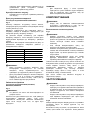
Switch action
Fig.4
CAUTION:
• Before plugging in the tool, always check to see
that the switch trigger actuates properly and returns
to the "OFF" position when released.
• Make sure that the shaft lock is released before the
switch is turned on.
To prevent the switch trigger from being accidentally
pulled, a lock button is provided.
To start the tool, depress the lock button and pull the
switch trigger. Release the switch trigger to stop.
For continuous operation, pull the switch trigger and then
depress the lock button further. To stop the tool, pull the
switch trigger so that the lock button returns
automatically. Then release the switch trigger.
After releasing the switch trigger, the lock-off function
works to prevent the switch trigger from being pulled.
CAUTION:
• Hold the tool firmly when turning off the tool, to
overcome the reaction.
Electronic function
For model RP2300FC,RP2301FC only
Constant speed control
• Possible to get fine finish, because the rotating
speed is kept constantly even under the loaded
condition.
• Additionally, when the load on the tool exceeds
admissible levels, power to the motor is reduced to
protect the motor from overheating. When the load
returns to admissible levels, the tool will operate as
normal.
Soft start feature
• Soft start because of suppressed starting shock.
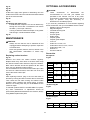
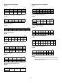
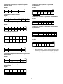
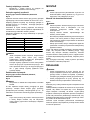
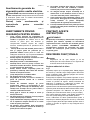
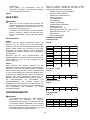
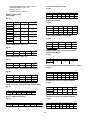
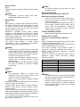
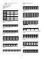
Speed adjusting dial
For model RP2300FC,RP2301FC only
Fig.5
The tool speed can be changed by turning the speed
adjusting dial to a given number setting from 1 to 6.
Higher speed is obtained when the dial is turned in the
direction of number 6. And lower speed is obtained when
it is turned in the direction of number 1.
This allows the ideal speed to be selected for optimum
material processing, i.e. the speed can be correctly
adjusted to suit the material and bit diameter.
Refer to the table for the relationship between the
number settings on the dial and the approximate tool
speed.
Number min
-1
1
2
3
4
5
9,000
11,000
14,000
17,000
20,000
622,000
009875
CAUTION:
• If the tool is operated continuously at low speeds
for a long time, the motor will get overloaded,
resulting in tool malfunction.
• The speed adjusting dial can be turned only as far
as 6 and back to 1. Do not force it past 6 or 1, or the
speed adjusting function may no longer work.
Lighting up the lamps
For model RP1800F, RP1801F, RP2300FC,RP2301FC
only
Fig.6
CAUTION:
• Do not look in the light or see the source of light
directly.
Pull the switch trigger to turn on the light. The lamp keeps
on lighting while the switch trigger is being pulled. The
lamp turns off 10 - 15 seconds after releasing the trigger.
NOTE:
• Use a dry cloth to wipe the dirt off the lens of lamp.
Be careful not to scratch the lens of lamp, or it may
lower the illumination.

10
ASSEMBLY
CAUTION:
• Always be sure that the tool is switched off and
unplugged before carrying out any work on the tool.
Installing or removing the bit
Fig.7
CAUTION:
• Install the bit securely. Always use only the wrench
provided with the tool. A loose or overtightened bit
can be dangerous.
• Use always a collet which is suitable for the shank
diameter of the bit.
• Do not tighten the collet nut without inserting a bit or
install small shank bits without using a collet sleeve.
Either can lead to breakage of the collet cone.
• Use only router bits of which the maximum speed,
as indicated on the bit, does exceed the maximum
speed of the router.
Insert the bit all the way into the collet cone. Press the
shaft lock to keep the shaft stationary and use the wrench
to tighten the collet nut securely. When using router bits
with smaller shank diameter, first insert the appropriate
collet sleeve into the collet cone, then install the bit as
described above.
To remove the bit, follow the installation procedure in
reverse.
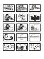
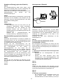
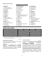
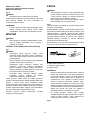
OPERATION
CAUTION:
• Before operation, always make sure that the tool
body automatically rises to the upper limit and the
bit does not protrude from the tool base when the
lock lever is loosened.
• Before operation, always make sure that the chip
deflector is installed properly.
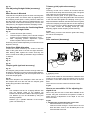
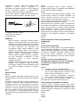
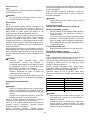
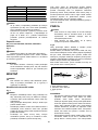
Fig.8
Always use both grips and firmly hold the tool by both
grips during operations.
Set the tool base on the workpiece to be cut without the
bit making any contact. Then turn the tool on and wait
until the bit attains full speed. Lower the tool body and
move the tool forward over the workpiece surface,
keeping the tool base flush and advancing smoothly until
the cutting is complete.
When doing edge cutting, the workpiece surface should
be on the left side of the bit in the feed direction.
12
3
44
2
001984
NOTE:
• Moving the tool forward too fast may cause a poor
quality of cut, or damage to the bit or motor. Moving
the tool forward too slowly may burn and mar the
cut. The proper feed rate will depend on the bit size,
the kind of workpiece and depth of cut. Before
beginning the cut on the actual workpiece, it is
advisable to make a sample cut on a piece of scrap
lumber. This will show exactly how the cut will look
as well as enable you to check dimensions.
• When using the straight guide or the trimmer guide,
be sure to install it on the right side in the feed
direction. This will help to keep it flush with the side
of the workpiece.
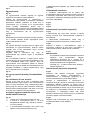
Fig.9
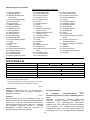
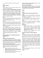
Straight guide
Fig.10
The straight guide is effectively used for straight cuts
when chamfering or grooving.
Install the straight guide on the guide holder with the
clamping screw (B). Insert the guide holder into the holes
in the tool base and tighten the clamping screw (A). To
adjust the distance between the bit and the straight guide,
loosen the clamping screw (B) and turn the fine adjusting
screw (1.5 mm per turn). At the desired distance, tighten
the clamping screw (B) to secure the straight guide in
place.
Fig.11
Wider straight guide of desired dimensions may be made
by using the convenient holes in the guide to bolt on extra
pieces of wood.
Fig.12
When using a large diameter bit, attach pieces of wood to
the straight guide which have a thickness of more than
15 mm to prevent the bit from striking the straight guide.
When cutting, move the tool with the straight guide flush
with the side of the workpiece.
If the distance between the side of the workpiece and the
cutting position is too wide for the straight guide, or if the
side of the workpiece is not straight, the straight guide
cannot be used. In this case, firmly clamp a straight
board to the workpiece and use it as a guide against the
trimmer base. Feed the tool in the direction of the arrow.
1. Workpiece
2. Bit revolving direction
3. View from the top of the tool
4. Feed direction

11
Fig.13
Fine Adjusting Straight Guide (accessory)
Fig.14
When Router is Mounted
Insert the two rods (Rod 10) into the outer mounting slots
of the guide holder, and secure them by tightening the
two clamping screws (M15 x 14mm). Check to make sure
that the thumb nut (M6 x 50mm) is tightened down, and
then slide the router's base mounting unit onto the two
rods (Rod 10), and tighten the base's clamping screws.
Fine Adjusting Function for Positioning Blade
in Relation to Straight Guide
Fig.15
1. Loosen thumb nut (M6 x 50mm).
2. Thumb nut (M10 x 52mm) can be turned to adjust
position (one turn adjusts the position by 1mm).
3. After completing position adjustment, tighten
thumb nut (M6 x 50mm) until secure.
Scale ring can be rotated separately, so scale unit can be
aligned to zero (0).
Guide Shoe Width Alteration
Loosen the screws marked by the circles to alter the
width of the guide shoe in the left and right directions.
After altering width, tighten the screws until they are
secure. Guide shoe width (d) alteration range is 280mm
to 350mm.
Fig.16
Fig.17
Fig.18
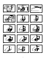
Templet guide (optional accessory)
Fig.19
The templet guide provides a sleeve through which the
bit passes, allowing use of the tool with templet patterns.
To install the templet guide, pull the lock plate lever and
insert the templet guide.
Fig.20
Secure the templet to the workpiece. Place the tool on
the templet and move the tool with the templet guide
sliding along the side of the templet.
Fig.21
NOTE:
• The workpiece will be cut a slightly different size
from the templet. Allow for the distance (X)
between the bit and the outside of the templet guide.
The distance (X) can be calculated by using the
following equation:
Distance (X) = (outside diameter of the templet
guide - bit diameter) / 2
Trimmer guide (optional accessory)
Fig.22
Trimming, curved cuts in veneers for furniture and the
like can be done easily with the trimmer guide. The guide
roller rides the curve and assures a fine cut.
Install the trimmer guide on the guide holder with the
clamping screw (B). Insert the guide holder into the holes
in the tool base and tighten the clamping screw (A). To
adjust the distance between the bit and the trimmer guide,
loosen the clamping screw (B) and turn the fine adjusting
screw (1.5 mm per turn). When adjusting the guide roller
up or down, loosen the clamping screw (C). After
adjusting, tighten all the clamping screws securely.
Fig.23
When cutting, move the tool with the guide roller riding
the side of the workpiece.
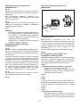
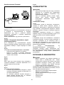
Fig.24
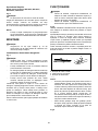
Dust nozzle set (Accessory)
1
2
009878
Use the dust nozzle for dust extraction. Install the dust
nozzle on the tool base using the thumb screw so that
protrusion on the dust nozzle fit to the notch in the tool
base.
Then connect a vacuum cleaner to the dust nozzle.
Fig.25
How to use screw M6 x 135 for adjusting the
depth of cut
When using the tool with a router table available in the
market, using this screw allows an operator to obtain a
small amount of adjustment of the depth of cut from
above the table.
Fig.26
1. Installing the screw and washer on the tool
• Attach flat washer onto this screw.
• Insert this screw through a screw hole in the tool
base and then screw in the threaded part in the
motor bracket of the tool.
1. Dust nozzle
2. Clamping screw

12
Fig.27
Fig.28
Fig.29
At this time, apply some grease or lubricating oil to the
inside of the screw hole in the tool base and the threaded
part in the motor bracket.
Fig.30
Fig.31
2. Adjusting the depth of cut
• A small amount of depth of cut can be obtained by
turning this screw with a screwdriver from above
the table. (1.0 mm per a full turn)
• Turning it clockwise makes the depth of cut greater
and turning it counterclockwise smaller.
Fig.32
MAINTENANCE
CAUTION:
• Always be sure that the tool is switched off and
unplugged before attempting to perform inspection
or maintenance.
• Never use gasoline, benzine, thinner, alcohol or the
like. Discoloration, deformation or cracks may
result.
Replacing carbon brushes
Fig.33
Remove and check the carbon brushes regularly.
Replace when they wear down to the limit mark. Keep
the carbon brushes clean and free to slip in the holders.
Both carbon brushes should be replaced at the same
time. Use only identical carbon brushes.
Use a screwdriver to remove the brush holder caps. Take
out the worn carbon brushes, insert the new ones and
secure the brush holder caps.
Fig.34
After replacing brushes, plug in the tool and break in
brushes by running tool with no load for about 10 minutes.
Then check the tool while running and electric brake
operation when releasing the switch trigger. If electric
brake is not working well, ask your local Makita service
center for repair.
To maintain product SAFETY and RELIABILITY, repairs,
any other maintenance or adjustment should be
performed by Makita Authorized Service Centers, always
using Makita replacement parts.
OPTIONAL ACCESSORIES
CAUTION:
• These accessories or attachments are
recommended for use with your Makita tool
specified in this manual. The use of any other
accessories or attachments might present a risk of
injury to persons. Only use accessory or
attachment for its stated purpose.
If you need any assistance for more details regarding
these accessories, ask your local Makita Service Center.
• Straight & groove forming bits
• Edge forming bits
• Laminate trimming bits
• Straight guide
• Trimmer guide
• Guide holder
• Templet guides
• Templet guide adapter
• Lock nut
• Collet cone 12 mm, 1/2"
• Collet sleeve 6 mm, 8 mm, 10 mm
• Collet sleeve 3/8", 1/4"
• Wrench 24
• Vacuum head set
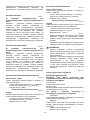
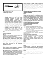
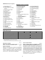
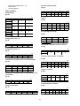
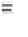
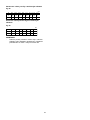
Router bits
Straight bit
Fig.35
mm
DA L 1 L 2
6
1/4"
8 8 60 25
6
1/4"
6
1/4" 65018
85018
20 50 15
1/2"
12
1/2"
12
12 60 30
10 60 25
006452
"U"Grooving bit
Fig.36
mm
DAL 1L 2R
6 6 50 18 3
006453
"V"Grooving bit
Fig.37
mm
DAL 1L 2
1/4" 20 50 15 90
006454

13
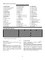
Drill point flush trimming bit
Fig.38
mm
D A L 1 L 2 L 3
12
8
6660
18 28
860 20 35
12 60 20 35
006456
Drill point double flush trimming bit
Fig.39
mm
D A L 1 L 2 L 3
6 6 70 40 12
L 4
14
006457
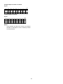
Board-jointing bit
Fig.40
mm
D A 1 A 2 L 1 L 2 L 3
12 2038 27 61 4
006459
Corner rounding bit
Fig.41
mm
D A 1 L 1 L 2 L 3
6
620 45 10 4
25
A 2
8
948 13 5
R
4
8
006460
Chamfering bit
Fig.42
mm
D A L 1 L 2 L 3
6
6
62049142
20 50 13 5
23 46 11 6 30
45
60
006462
Cove beading bit
Fig.43
mm
DAL 1L 2R
20 43 8 46
6254813 8
006464
Ball bearing flush trimming bit
Fig.44
mm
DA L 1 L 2
6
1/4" 10 50 20
006465
Ball bearing corner rounding bit
Fig.45
mm
D A 1 A 2 L 1 L 2 L 3 R
6
6
1/4"
3.5 3
3.5 6
21
40 10
15 8 37 7
21 8
8 40 10 3.5 6
006466
Ball bearing chamfering bit
Fig.46
mm
D A 1 L 1
26 42
6
1/4" 45
60620
A 2
8
841
L 2
12
11
006467
Ball bearing beading bit
Fig.47
mm
D A 1 A 2 A 3 L 1 L 2 L 3 R
6
6
5.5 4
4.5
10
12 726 12 8 42
20 12 8 40
006468
Ball bearing cove beading bit
Fig.48
mm
D A 1 A 2 A 4 L 1 L 2 L 3 R
6
6
5.5 3
5
10
12 526 22 8 42
20 18 8
A 3
12
12 40
006469
Ball bearing roman ogee bit
Fig.49
mm
D A 1 A 2 L 1 L 2 L 3 R1 R2
6
6
2.5 4.5
3
4.5
4.5 626 8 42 12
20 8 40 10
006470
NOTE:
• Some items in the list may be included in the tool
package as standard accessories. They may differ
from country to country.

14
УКРАЇНСЬКА (Оригінальні інструкції)
Пояснення до загального виду
1-1. Ручка регулювання
1-2. Стопорний важіль
1-3. Гайка налаштування штанги
стопора
1-4. Кнопка швидкої подачі
1-5. Болт регулювання
1-6. Блок стопора
1-7. Покажчик глибини
1-8. Штанга стопора
2-1. Нейлонова гайка
3-1. Штанга стопора
3-2. Болт регулювання
3-3. Блок стопора
4-1. Фіксатор
4-2. Кнопка вимикача
5-1. Диск регулювання швидкості
6-1. Ліхтар
7-1. Фіксатор
7-2. Ключ
9-1. Напрям подачі
9-2. Напрям обертання голівки
9-3. Деталь
9-4. Пряма лінійка
10-1. Пряма лінійка
10-2. Гвинт тонкого регулювання
10-3. Затискний гвинт (В)
10-4. Затискний гвинт (А)
10-5. Держак напрямної
12-1. Більш ніж 15 мм
12-2. Пряма лінійка
12-3. Деревина
15-1. Гвинт регулювання
16-1. Гвинти
16-2. Рухлива
17-1. Коли встановлено мінімальну
ширину розкриття
18-1. Коли встановлено максимальну
ширину розкриття
20-1. Напрямна шаблону
20-2. Планка блокування
21-1. Свердло
21-2. Основа
21-3. Шаблон
21-4. Деталь
21-5. Відстань (Х)
21-6. Зовнішній діаметр напрямної
шаблона
21-7. Напрямна шаблону
23-1. Держак напрямної
23-2. Гвинт регулювання
23-3. Затискний гвинт (В)
23-4. Затискний гвинт (С)
23-5. Напрямна тримера
23-6. Затискний гвинт (А)
24-1. Свердло
24-2. Напрямний ролик
24-3. Деталь
26-1. Плоска шайба 6
26-2. Гвинт M6x135
27-1. Плоска шайба 6
27-2. Гвинт M6x135
28-1. Отвір
29-1. Гвинт M6x135
29-2. Різьбовий отвір у рухливій
частині
30-1. Внутрішня частина отвору для
гвинта на основі інструменту
31-1. Різьбовий отвір у рухливій
частині
32-1. Викрутка
33-1. Обмежувальна відмітка
34-1. Ковпачок щіткотримача
34-2. Викрутка
ТЕХНІЧНІ ХАРАКТЕРИСТИКИ
Модель
RP1800/RP1800F RP1801/RP1801F
RP2300FC RP2301FC
Потужність цангового патрона 12 мм або 1/2"
Здатність занурення 0 - 70 мм
Швидкість холостого ходу (хв.-1) 22000 9000 - 22000
Загальна довжина 312 мм
Чиста вага 6,0 кг 6,1 кг
Клас безпеки /II
• Через те, що ми не припиняємо програми досліджень і розвитку, наведені тут технічні характеристики можуть бути змінені
без попередження.
• Примітка. У різних країнах технічні характеристики можуть бути різними.
• Вага відповідно до EPTA-Procedure 01/2003
ENE010-1
Призначення
Інструмент призначено для відрізання бокових
поздовжніх звисів та фасонної обробки деревини,
пластмаси та подібних матеріалів.
ENF002-1
Джерело живлення
Інструмент можна підключати лише до джерела
струму, що має напругу, зазначену в табличці з
заводськими характеристиками, і він може працювати
лише від однофазного джерела перемінного струму.
Інструмент має подвійну ізоляцію згідно з
європейським стандартом і, отже, може підключатися
до розеток без клеми заземлення.
Для моделі RP1800
ENF100-1
Для використання від низьковольтної мережі від
220В до 250 В.
Увімкнення та вимкнення електричного приладу
спричиняє до коливання напруги. Експлуатація цього
пристрою за несприятливих умов сіті може погано
вплинути на роботу іншого обладнання. Можна
припустити, що при опорі мережі 0,40 Ом або нижче,
ніякого негативного впливу не буде. Мережна розетка,
до якої буде підключатися пристрій, повинна буди
захищена запобіжником або захисним автоматичним

15
вимикачем плавного розчіплювання.
Для моделі RP1800F
ENF100-1
Для використання від низьковольтної мережі від
220В до 250 В.
Увімкнення та вимкнення електричного приладу
спричиняє до коливання напруги. Експлуатація цього
пристрою за несприятливих умов сіті може погано
вплинути на роботу іншого обладнання. Можна
припустити, що при опорі мережі 0,39 Ом або нижче,
ніякого негативного впливу не буде. Мережна розетка,
до якої буде підключатися пристрій, повинна буди
захищена запобіжником або захисним автоматичним
вимикачем плавного розчіплювання.
Для моделі RP1801,RP1801F
ENF100-1
Для використання від низьковольтної мережі від
220В до 250 В.
Увімкнення та вимкнення електричного приладу
спричиняє до коливання напруги. Експлуатація цього
пристрою за несприятливих умов сіті може погано
вплинути на роботу іншого обладнання. Можна
припустити, що при опорі мережі 0,38 Ом або нижче,
ніякого негативного впливу не буде. Мережна розетка,
до якої буде підключатися пристрій, повинна буди
захищена запобіжником або захисним автоматичним
вимикачем плавного розчіплювання.
Для моделі RP1800,RP1800F,RP1801,RP1801F
ENG102-3
Шум
Рівень шуму за шкалою А у типовому виконанні,
визначений відповідно до EN60745:
Рівень звукового тиску (LpA) : 86 дБ(A)
Рівень звукової потужності (LWA): 97 дБ(A)
Погрішність (К): 3 дБ(A)
Обов'язково використовуйте протишумові
засоби
ENG223-2
Вібрація
Загальна величина вібрації (сума трьох векторів),
визначена згідно з EN60745:
Режим роботи: різання пазів в МДФ
Вібрація (aгод) : 4,0 м/с2
Похибка (К): 1,5 м/с2
Для моделі RP2300FC,RP2301FC
ENG102-3
Шум
Рівень шуму за шкалою А у типовому виконанні,
визначений відповідно до EN60745:
Рівень звукового тиску (LpA) : 87 дБ(A)
Рівень звукової потужності (LWA): 98 дБ(A)
Погрішність (К): 3 дБ(A)
Обов'язково використовуйте протишумові
засоби
ENG223-2
Вібрація
Загальна величина вібрації (сума трьох векторів),
визначена згідно з EN60745:
Режим роботи: різання пазів в МДФ
Вібрація (aгод) : 4,5 м/с2
Похибка (К): 1,5 м/с2
ENG901-1
• Заявлене значення вібрації було виміряно у
відповідності до стандартних методів
тестування та може використовуватися для
порівняння одного інструмента з іншим.
•
Заявлене значення вібрації може також
використовуватися для попередньої оцінки впливу.
УВАГА:
• Залежно від умов використання вібрація під час
фактичної роботи інструмента може
відрізнятися від заявленого значення вібрації.
• Забезпечте належні запобіжні заходи для
захисту оператора, що відповідатимуть умовам
використання інструмента (слід брати до уваги
всі складові робочого циклу, такі як час, коли
інструмент вимкнено та коли він починає
працювати на холостому ході під час запуску).
ENH101-15
Тільки для країн Європи
Декларація про відповідність стандартам
ЄС
Наша компанія, Makita Corporation, як
відповідальний виробник, наголошує на тому, що
обладнання Makita:
Позначення обладнання:
Фрезер
№ моделі/ тип:
RP1800,RP1800F,RP1801,RP1801F,RP2300FC,RP2301FC
є серійним виробництвом та
Відповідає таким Європейським Директивам:
2006/42/EC
Та вироблені у відповідності до таких стандартів та
стандартизованих документів:
EN60745
Технічна документація знаходиться у нашого
уповноваженого представника в Європі, а саме:
Makita International Europe Ltd.
Michigan Drive, Tongwell,
Milton Keynes, Bucks MK15 8JD, Англія

16
26.10.2010
000230
Tomoyasu Kato
Директор
Makita Corporation
3-11-8, Sumiyoshi-cho,
Anjo, Aichi, 446-8502, ЯПОНІЯ
GEA010-1
Застереження стосовно техніки
безпеки при роботі з
електроприладами
УВАГА! Прочитайте усі застереження
стосовно техніки безпеки та всі інструкції.
Недотримання даних застережень та інструкцій може
призвести до ураження струмом та виникнення
пожежі та/або серйозних травм.
Збережіть усі інструкції з техніки
безпеки та експлуатації на майбутнє.
GEB018-3
ПОПЕРЕДЖЕННЯ ПРО
НЕБЕЗПЕКУ ПІД ЧАС РОБОТИ З
ФРЕЗЕРОМ
1. Тримайте електроприлад за ізольовані
поверхні держака під час виконання дії,
тому що різак може зачепити власний шнур.
Розрізання струмоведучої проводки може
призвести до передання напруги до оголених
металевих частин електроприладу та до
ураження оператора електричним струмом.
2. За допомогою затискних пристроїв або
якогось іншого дієвого способу слід
забезпечити опору деталі та закріпити
деталь на стійкій поверхні. Утримування
деталі руками або тілом не фіксує деталь та
може призвести до втрати контролю.
3. Під час тривалої роботи слід одягати
засоби для захисту органів слуху.
4. Дуже обережно поводьтесь з голівками.
5. Перед початком роботи слід ретельно
перевірити полотно на наявність тріщин
або пошкодження. Слід негайно замінити
тріснуті або пошкоджені голівки.
6. Слід уникати різання цвяхів. Перед
початком роботи огляньте та заберіть усі
цвяхи з деталі.
7. Міцно тримай інструмент обома руками.
8. Не торкайтесь руками частин, що
обертаються.
9. Перевірте, щоб голівка не торкалася деталі
перед увімкненням.
10. Перед початком різання деталі, запустіть
інструмент та дайте попрацювати йому
деякий час. Перевірте чи не коливає або не
виляє вона, що вказує на неправильне
встановлення голівки.
11. Слід уважно стежити за напрямком
обертання голівки та напрямком подачі.
12. Не залишайте інструмент працюючим.
Працюйте з інструментом тільки тоді, коли
тримаєте його в руках.
13. Обов'язково після вимкнення інструменту
заждіть доки голівка не зупиниться
повністю, та лише тоді знімайте її з деталі.
14. Не торкайтесь полотна або деталі одразу
після різання, воно може бути дуже гарячим
та призвести до опіку шкіри.
15. Не слід вимазувати основу інструменту
через недбайливість розчинником,
бензином або мастилом і т.і. Вони можуть
призвести до тріщин основи інструменту.
16. Під час користування різаками слід
звертати увагу на діаметр хвостовика, який
повинен відповідати швидкості
інструменту.
17. Деякі матеріали мають у своєму складі
токсичні хімічні речовини. Будьте уважні,
щоб запобігти вдихання пилу та контактів зі
шкірою. Дотримуйтеся правил техніки
безпеки виробника матеріалу .
18. Завжди використовуйте пилозахисну
маску/респіратор що відповідають області
застосування та матеріалу, що ви
обробляєте.
ЗБЕРІГАЙТЕ ЦІ ВКАЗІВКИ.
УВАГА:
НІКОЛИ НЕ СЛІД втрачати пильності та
розслаблюватися під час користування виробом
(що приходить при частому використанні); слід
завжди строго дотримуватися правил безпеки під
час використання цього пристрою. НЕНАЛЕЖНЕ
ВИКОРИСТАННЯ або недотримання правил
безпеки, викладених в цьому документі, може
призвести до серйозних травм.

17
ІНСТРУКЦІЯ З ВИКОРИСТАННЯ
ОБЕРЕЖНО:
• Перед регулюванням та перевіркою справності
інструменту, переконайтеся в тому, що він
вимкнений та відключений від мережі.
Порядок регулювання глибини різання
Fig.1
Встановіть інструмент на пласку поверхню. Послабте
важіль блокування та опустіть корпус інструменту так,
щоб голівка злегка торкалась пласкої поверхні.
Затягніть важіль блокування, щоб зафіксувати корпус
інструменту.
Поверніть гайку налаштування штанги стопора проти
годинникової стрілки. Опустіть штангу стопора, щоб
вона торкалась болта регулювання. Сумістіть
покажчик глибини із поділкою "0". Глибина різання
вказується на шкалі покажчиком глибини.
Натискаючи кнопку швидкої подачі, підніміть штангу
стопора, доки не буде отримано необхідну глибину
різання. Хвилинні регулювання глибини можна
виконати шляхом повертання ручки регулювання (1
мм за поворот).
Повертаючи гайку налаштування штанги стопора за
годинниковою стрілкою, можна міцно закріпити
штангу стопора.
Тепер визначену глибину різання можна отримати,
послабивши важіль блокування, а потім опустивши
корпус інструменту таким чином, щоб він торкався
болта регулювання з шестигранною головкою з блока
стопора.
Нейлонова гайка
Fig.2
Повертаючи нейлонову гайку можна відрегулювати
верхнє обмеження корпуса інструмента.
ОБЕРЕЖНО:
• Не можна опускати нейлонову гайку занадто
низько. Голівка буде небезпечно виступати.
Блок стопора
Fig.3
Блок стопора має три болти регулювання з
шестигранними головками, які опускають або
піднімають на 0,8 мм за поворот. Можна легко
налаштувати три різних глибини різання за допомогою
цих болтів регулювання з шестигранними головками
без повторного регулювання штанги стопора.
Відрегулюйте найнижчий болт з шестигранною
головкою для отримання найбільшої глибини різання,
застосовуючи методику, описану у розділі
"Регулювання глибини різання". Відрегулюйте два
болти з шестигранними головками, що залишились,
для отримання меншої глибини різання. Різниця у
висоті цих болтів з шестигранними головками
дорівнює різниці у глибині різання.
Для регулювання болтів з шестигранними головками
поверніть їх за допомогою викрутки або гайкового
ключа. Блок стопора також є зручним для виконання
трьох проходів із поступово збільшеною глибиною під
час різання глибоких пазів.
ОБЕРЕЖНО:
• Оскільки надмірне різання може призвести до
перевантаження мотора або утруднити
контроль інструмента, глибина різання не
повинна перевищувати 15 мм за один прохід під
час прорізання пазів голівкою діаметром 8 мм.
• Коли пази нарізаються голівкою діаметром 20
мм, глибина різання не повинна перевищувати 5
мм за прохід.
• Для робіт з вирізання глибоких пазів, слід
робити два або три проходи, поступово
збільшуючи глибину.
Дія вимикача.
Fig.4
ОБЕРЕЖНО:
• Перед вмиканням інструменту у мережу
обов'язково перевірте, чи кнопка вимикача
нормально спрацьовує і після відпускання
повертається в положення "вимкнено".
• Перевірте, щоб блокування вала було
відпущене перед тим, як перемикач буде
увімкнений.
Для того щоб запобігти випадковому натисканню
курка вмикача, передбачена кнопка блокування.
Для того, щоб запустити інструмент, натисніть на
кнопку блокування та натисніть на курок вимкненого
положення. Для зупинки відпустіть курок вмикача.
Для постійної роботи слід натиснути на курок вмикача,
а потім ще раз натиснути на кнопку блокування. Для
того, щоб зупинити інструмент, слід натиснути на
курок вмикача, щоб кнопка блокування автоматично
повернулась в початкове положення. Потім відпустіть
курок вмикача.
Після того, як курок вмикача був відпущений,
спрацьовує функція блокування вимкненого
положення для запобігання випадкового натискання
курка вмикача.
ОБЕРЕЖНО:
• Під час вимикання інструмент слід міцно
тримати, щоб перебороти реакцію.
Електронні функції
Тільки для моделей RP2300FC,RP2301FC
Постійний контроль швидкості
• Дає можливість отримати чисту обробку, тому
ще швидкість обертання підтримується на
постійному рівні, навіть під навантаженням.
• До того ж, коли навантаження на інструмент
перевищує припустимі рівні, то потужність
мотора знижується для його захисту від

18
перегріву. Коли навантаження повертається до
дозволенного рівня, інструмент починає
працювати в нормальному режимі.
Функція плавного запуску
• Плавний запуск за рахунок стримання ривка під
час запуску.
Диск регулювання швидкості
Тільки для моделей RP2300FC,RP2301FC
Fig.5
Загальну швидкість інструменту можна змінити,
повернувши диск регулювання на відповідний номер
налаштування від 1 до 6.
Швидкість підвищується при повертанні диска у
напрямку номера 6. Швидкість зменшується при
повертанні диска у напрямку номера 1.
Це дозволяє обрати оптимальну для обробки
матеріалу швидкість, тобто швидкість можна вірно
відрегулювати відповідно до матеріалу і діаметра
голівки.
Відношення між номером налаштування на диску та
приблизною швидкістю обертання дивіться у
наведеній нижче таблиці.
Номер min
-1
1
2
3
4
5
9000
11000
14000
17000
20000
622000
009875
ОБЕРЕЖНО:
• Якщо інструмент протягом тривалого часу
безперервно експлуатується на низький
швидкості, мотор перевантажується. що
призводить до порушень в роботі інструмента.
• Диск регулювання швидкості можна повертати
тільки від 1 до 6 та назад. Не намагайтесь
повернути його силою за межу 1 або 6, бо це
може зламати функцію регулювання.
Увімкнення підсвітки
Тільки для моделей RP1800F, RP1801F,
RP2300FC,RP2301FC
Fig.6
ОБЕРЕЖНО:
• Не дивіться на світло або безпосередньо на
джерело світла.
Натисніть на курок вмикача для того, щоб увімкнути
підсвічування. Лампочка горить, поки курок
залишається натиснутим. Лампочка вимикається
через 10-15 секунд після того, як курок було
відпущено.
ПРИМІТКА:
• Для видалення бруду з лінзи підсвітки
користуйтесь сухою тканиною. Будьте обережні,
щоб не подряпати лінзу підсвітки, тому що
можна погіршити освітлювання.
КОМПЛЕКТУВАННЯ
ОБЕРЕЖНО:
• Перед тим, як зайнятись комплектуванням
інструменту, переконайтеся в тому, що він
вимкнений та відключений від мережі.
Встановлення та зняття долота
Fig.7
ОБЕРЕЖНО:
• Надійно встановіть голівку. Слід завжди
використовувати тільки ключ, що поставляється
разом із інструментом. Послаблена або занадто
сильно затягнута голівка може становити
небезпеку.
• Слід завжди використовувати цангу, що
підходить під діаметр потилиці голівки.
• Неможна затягувати гайку цанги без вставленої
голівки, або встановлювати потилиці голівки без
муфти цанги. Це може призвести до поломки
конуса цанги.
• Можна використовувати тільки такі голівки
фрезера, максимальна швидкість яких не
перевищує максимальної швидкості фрезера.
Повністю вставте голівку в конус цанги. Натисніть на
блокування вала, щоб він не рухався та за допомогою
ключа надійно затягніть гайку цанги. У разі
використання фрезерних голівок, із меншим
діаметром потилиці, слід спочатку вставити
відповідну муфту цанги в конус цанги, а потім
встановити голівку, к описано вище.
Для зняття голівки слід виконати інструкції в
зворотному порядку.
ЗАСТОСУВАННЯ
ОБЕРЕЖНО:
• Перед початком роботи слід завжди перевіряти,
щоб корпус інструмента автоматично піднімався
до верхньої межі, та щоб голівка не виступала з
корпуса інструмента, коли важіль блокування
послаблений.
• Перед початком роботи слід завжди перевіряти,
щоб відбивна перегородка для тирси була
належним чином встановлена.
Fig.8
Завжди використовуйте обидві рукоятки та тримайте
інструмент міцно за обидві рукоятки під час
експлуатації.
Встановіть основу на деталь, що різатиметься таким
чином, щоб голівка її не торкалась. Потім увімкніть

19
інструмент та заждіть, доки блок набере повної
швидкості. Опустіть корпус інструмента та
пересувайте інструмент вперед по деталі, тримаючи
основу інструмента урівень та пересуваючись
поступово, доки різання не буде завершене.
Під час зняття фасок, поверхня деталі повинна бути
встановлена зліва від голівки у напрямку подачі.
12
3
44
2
001984
ПРИМІТКА:
• Якщо інструмент пересувати вперед занадто
швидко, то це може призвести до поганої якості
обробки або поломки голівки або мотора. Якщо
інструмент пересувати вперед занадто повільно,
це може призвести до обпікання або
спотворення прорізу. Вірна швидкість подачі
залежить від розміру голівки, типу деталі та
глибини різання. Перед тим, як починати різання
власне деталі, рекомендовано спочатку
виконати пробне різання на шматку з відходів.
Це дасть можливість подивитись, як саме
виглядатиме проріз, а також дозволить
перевірити розміри.
• Використовуючи пряму напрямну або напрямну
тримера, слід перевірити, щоб вона була
встановлена з правої сторони в напрямку подачі.
Це допоможе тримати її урівень зі стороною
деталі.
Fig.9
Пряма лінійка
Fig.10
Пряма напрямна ефективно використовується для
прямих прорізів під час фальцювання або нарізання
канавок.
Встановіть пряму напрямну на держак напрямної за
допомогою затискного гвинта (В). Вставте держак
напрямної в отвори на основі інструменту та затягніть
затискний гвинт (А). Для регулювання відстані між
голівкою та прямою напрямною послабте затискний
гвинт (В) та поверніть гвинт тонкого регулювання (1,5
мм за поворот). На необхідній відстані затягніть
затискний гвинт (В) та надійно закріпіть на місці пряму
напрямну.
Fig.11
Можна встановити ширшу пряму напрямну з
використанням отворів у напрямній, щоб прикріпити
до неї додаткові шматки деревини.
Fig.12
У разі використання голівки великого діаметру, слід
додати шматок дерева до прямої напрямної, що
мають товщину не менш 15 мм, для того, щоб
запобігти биттю голівки об пряму напрямну.
Під час різання слід пересувати інструмент так, щоб
пряма напрямна була урівень з деталлю.
Якщо відстань між стороною деталі та положенням
для різання дуже велика для прямої напрямної або
якщо сторона деталі не є прямою, пряму напрямну
використовувати не можна. В такому випадку слід
міцно притиснути пряму дошку до деталі та
використати її як напрямну відносно основи тримера.
Інструмент слід подавати у напрямку, що вказаний
стрілкою.
Fig.13
Пряма напрямна тонкого регулювання
(приладдя)
Fig.14
Встановлення фрезера
Вставте два стрижні (стрижень 10) у крайні кріпильні
отвори держака напрямної та затягніть їх надійно
двома затискними гвинтами (M15 x 14мм). Перевірте,
чи затягнута смушкова гайка (M6 x 50мм), а потім
вставте два стрижні (стрижень 10) у кріпильну
частину основи фрезера та затягніть затискні гвинти
основи.
Функція тонкого регулювання для
встановлення ріжучої частини у необхідне
положення по відношенню до прямої
напрямної
Fig.15
1. Послабте смушкову гайку (M6 x 50мм).
2. Смушкову гайку (M10 x 52мм) можна повертати,
для того щоб відрегулювати положення (один
поворот регулює положення на 1 мм).
3. Після закінчення регулювання положення
міцно затягніть смушкову гайку (M6 x 50мм).
Диск зі шкалою можна обертати окремо для
встановлення покажчика шкали на нуль (0).
Зміна ширини напрямного башмака
Послабте гвинти, позначені колами, щоб змінити
ширину напрямного башмака вліво або вправо. Після
зміни ширини міцно затягніть гвинти. Діапазон зміни
ширини напрямного башмака (d) становить від 280
мм до 350 мм.
Fig.16
Fig.17
Fig.18
1. Деталь
2. Напрям обертання голівки
3. Від зверху інструмента
4. Напрям подачі

20
Шаблонна напрямна (додаткова
приналежність)
Fig.19
Шаблонна напрямна має гільзу, через яку проходить
голівка, що дозволяє використовувати інструмент із
шаблонами.
Для встановлення шаблонної напрямної слід
потягнути за важіль планки блокування та вставити
шаблонну напрямну.
Fig.20
Закріпіть шаблон на деталі. Встановіть інструмент на
шаблон та пересувайте інструмент з шаблонною
напрямною уздовж шаблона.
Fig.21
ПРИМІТКА:
• Розмір прорізаної деталі дещо відрізнятиметься
від розміру шаблона. Забезпечте відстань (Х)
між голівкою та зовнішнім краєм шаблонної
напрямної. Відстань (Х) можна розрахувати за
допомогою наступного рівняння:
Відстань (Х) = (зовнішній діаметр шаблонної
напрямної - діаметр голівки) / 2
Напрямна тримера (додаткова
приналежність)
Fig.22
Обробка, різання по кривій меблевої фанери та ін.,
можуть легко виконуватись за допомогою напрямної
тримера. Ролик напрямної іде по кривій та забезпечує
чисте різання.
Встановіть напрямну тримера на держак напрямної
за допомогою затискного гвинта (В). Вставте держак
напрямної в отвори на основі інструменту та затягніть
затискний гвинт (А). Для регулювання відстані між
голівкою та напрямною тримера послабте затискний
гвинт (В) та поверніть гвинт тонкого регулювання (1,5
мм за поворот). Для регулювання напрямного ролика
по висоті послабте затискний гвинт (С). Після
регулювання надійно затягніть усі затискні гвинти.
Fig.23
Під час різання слід пересувати інструмент так, щоб із
ролик напрямної йшов по стороні деталі.
Fig.24
Комплект наконечників для пилу
(додатково)
1
2
009878
Використовуйте наконечники для пилу для
пиловидалення. Встановіть наконечник для пилу на
основу інструменту за допомогою гвинта з накатаною
головкою таким чином, щоб виступ на наконечнику
для пилу ввійшов без зазору у виїмку на основі
інструменту.
Потім підключіть пилосос до наконечнику для пилу.
Fig.25
Як за допомогою гвинта M6 x 135
регулювати глибину різання
При використанні інструменту зі столом для фрезера,
доступним у продажу, використання цього гвинта
дозволяє оператору отримати незначний діапазон
регулювання глибини різання понад столом.
Fig.26
1. Встановлення гвинта і шайби на інструмент
• Прикріпіть плоску шайбу на цей гвинт.
• Вставте цей гвинт в отвір для гвинта на основі
інструменту та вкрутіть його у різьбовий отвір у
рухливій частині інструменту.
Fig.27
Fig.28
Fig.29
У цей час нанесіть трохи мастила або мастильного
матеріалу на внутрішню частину отвору для гвинта на
основі інструменту та на різьбовий отвір у рухливій
частині.
Fig.30
Fig.31
2. Регулювання глибини різання
• Незначний діапазон глибини різання можна
отримати, повернувши цей гвинт за допомогою
викрутки над столом. (1,0 мм за повний поворот)
1. Штуцер для пилу
2. Затискний гвинт
Pagina se încarcă...
Pagina se încarcă...
Pagina se încarcă...
Pagina se încarcă...
Pagina se încarcă...
Pagina se încarcă...
Pagina se încarcă...
Pagina se încarcă...
Pagina se încarcă...
Pagina se încarcă...
Pagina se încarcă...
Pagina se încarcă...
Pagina se încarcă...
Pagina se încarcă...
Pagina se încarcă...
Pagina se încarcă...
Pagina se încarcă...
Pagina se încarcă...
Pagina se încarcă...
Pagina se încarcă...
Pagina se încarcă...
Pagina se încarcă...
Pagina se încarcă...
Pagina se încarcă...
Pagina se încarcă...
Pagina se încarcă...
Pagina se încarcă...
Pagina se încarcă...
Pagina se încarcă...
Pagina se încarcă...
Pagina se încarcă...
Pagina se încarcă...
Pagina se încarcă...
Pagina se încarcă...
Pagina se încarcă...
Pagina se încarcă...
Pagina se încarcă...
Pagina se încarcă...
Pagina se încarcă...
Pagina se încarcă...
Pagina se încarcă...
Pagina se încarcă...
Pagina se încarcă...
Pagina se încarcă...
Pagina se încarcă...
Pagina se încarcă...
Pagina se încarcă...
Pagina se încarcă...
Pagina se încarcă...
Pagina se încarcă...
Pagina se încarcă...
Pagina se încarcă...
Pagina se încarcă...
Pagina se încarcă...
Pagina se încarcă...
Pagina se încarcă...
Pagina se încarcă...
Pagina se încarcă...
Pagina se încarcă...
Pagina se încarcă...
-
 1
1
-
 2
2
-
 3
3
-
 4
4
-
 5
5
-
 6
6
-
 7
7
-
 8
8
-
 9
9
-
 10
10
-
 11
11
-
 12
12
-
 13
13
-
 14
14
-
 15
15
-
 16
16
-
 17
17
-
 18
18
-
 19
19
-
 20
20
-
 21
21
-
 22
22
-
 23
23
-
 24
24
-
 25
25
-
 26
26
-
 27
27
-
 28
28
-
 29
29
-
 30
30
-
 31
31
-
 32
32
-
 33
33
-
 34
34
-
 35
35
-
 36
36
-
 37
37
-
 38
38
-
 39
39
-
 40
40
-
 41
41
-
 42
42
-
 43
43
-
 44
44
-
 45
45
-
 46
46
-
 47
47
-
 48
48
-
 49
49
-
 50
50
-
 51
51
-
 52
52
-
 53
53
-
 54
54
-
 55
55
-
 56
56
-
 57
57
-
 58
58
-
 59
59
-
 60
60
-
 61
61
-
 62
62
-
 63
63
-
 64
64
-
 65
65
-
 66
66
-
 67
67
-
 68
68
-
 69
69
-
 70
70
-
 71
71
-
 72
72
-
 73
73
-
 74
74
-
 75
75
-
 76
76
-
 77
77
-
 78
78
-
 79
79
-
 80
80


Makita RP1800 Manual de utilizare
- Categorie
- Unelte electrice
- Tip
- Manual de utilizare
în alte limbi
- slovenčina: Makita RP1800 Používateľská príručka
- polski: Makita RP1800 Instrukcja obsługi
Lucrări înrudite
-
Makita RP1802 Manual de utilizare
-
Makita RP1111C Manual de utilizare
-
-
-
Makita 3709 Manual de utilizare
-
Makita M3600 Manual de utilizare
-
Makita 3712 Manual de utilizare
-
Makita M3700 Manual de utilizare
-
Makita LF1000 Manual de utilizare
-
Makita SP6000 Manual de utilizare
