
RP1802
RP1802F
RP1803
RP1803F
RP2302FC
RP2303FC
EN Router INSTRUCTION MANUAL 9
SL Rezkar NAVODILA ZA UPORABO 17
SQ Freza MANUALI I PËRDORIMIT 25
BG Фреза РЪКОВОДСТВО ЗА
ЕКСПЛОАТАЦИЯ 33
HR Glodalica PRIRUČNIK S UPUTAMA 42
МК Глодач УПАТСТВО ЗА УПОТРЕБА 50
SR Глодалица УПУТСТВО ЗА УПОТРЕБУ 59
RO Maşină de frezat verticală MANUAL DE INSTRUCŢIUNI 68
UK Фрезер ІНСТРУКЦІЯ З
ЕКСПЛУАТАЦІЇ 76
RU Фрезер РУКОВОДСТВО ПО
ЭКСПЛУАТАЦИИ 85

2
4
7
8
15
6
2
3
Fig.1
1
Fig.2
1
2
3
Fig.3
1
2
Fig.4
1
Fig.5
1
Fig.6
1
Fig.7
1
2
3
4
Fig.8

3
1
Fig.9
Fig.10
1
2
3
44
2
Fig.11
1
23
4
Fig.12
1
2
3
4
5
Fig.13
C1
A
B
2
Fig.14
Fig.15
1
2
3
Fig.16

4
1
2
3
Fig.17
1
Fig.18
Fig.19
Fig.20
Fig.21
1
2
Fig.22
1
2
3
5
6
4
(X)
Fig.23
1
Fig.24

5
1
2
3
45
6
Fig.25
3
1
2
Fig.26
1
2
Fig.27
Fig.28
2
1
Fig.29
1
Fig.30
1
2
Fig.31
1
Fig.32

6
1
Fig.33
1
Fig.34
Fig.35
R
Fig.36
Fig.37
Fig.38
Fig.39
Fig.40

7
Fig.41
Fig.42
Fig.43
Fig.44
Fig.45
Fig.46
Fig.47
Fig.48

8
Fig.49

9ENGLISH
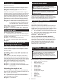
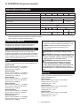
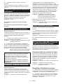
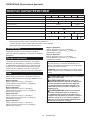
ENGLISH (Original instructions)
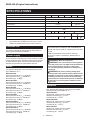
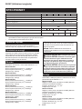
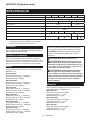
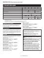
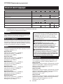
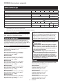
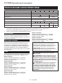
SPECIFICATIONS
Model: RP1802
RP1802F
RP1803
RP1803F
RP2302FC RP2303FC
Collet chuck capacity 12 mm or 1/2″
Plunge capacity 0 - 70 mm
No load speed 23,000 min-1 22,000 min-1 9,000 - 23,000 min-1
Overall height 312 mm 327 mm
Net weight 6.2 kg
Safety class /II
Lamp - -
Speed adjusting dial -
Electric brake - -
•
Due to our continuing program of research and development, the specications herein are subject to change without notice.
• Specications may dier from country to country.
• Weight according to EPTA-Procedure 01/2014
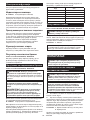
Intended use
The tool is intended for ush trimming and proling of
wood, plastic and similar materials.
Power supply
The tool should be connected only to a power supply of the same
voltage as indicated on the nameplate, and can only be operated
on single-phase AC supply. They are double-insulated and can,
therefore, also be used from sockets without earth wire.
Noise
The typical A-weighted noise level determined accord-
ing to EN62841-2-17:
Model RP1802
Sound pressure level (LpA) : 85 dB(A)
Sound power level (LWA) : 96 dB (A)
Uncertainty (K) : 3 dB(A)
Model RP1802F
Sound pressure level (LpA) : 85 dB(A)
Sound power level (LWA) : 96 dB (A)
Uncertainty (K) : 3 dB(A)
Model RP1803
Sound pressure level (LpA) : 85 dB(A)
Sound power level (LWA) : 96 dB (A)
Uncertainty (K) : 3 dB(A)
Model RP1803F
Sound pressure level (LpA) : 85 dB(A)
Sound power level (LWA) : 96 dB (A)
Uncertainty (K) : 3 dB(A)
Model RP2302FC
Sound pressure level (LpA) : 88 dB(A)
Sound power level (LWA) : 99 dB (A)
Uncertainty (K) : 3 dB(A)
Model RP2303FC
Sound pressure level (LpA) : 88 dB(A)
Sound power level (LWA) : 99 dB (A)
Uncertainty (K) : 3 dB(A)
NOTE: The declared noise emission value(s) has
been measured in accordance with a standard test
method and may be used for comparing one tool with
another.
NOTE: The declared noise emission value(s)
may also be used in a preliminary assessment of
exposure.
WARNING: Wear ear protection.
WARNING: The noise emission during actual
use of the power tool can dier from the declared
value(s) depending on the ways in which the
tool is used especially what kind of workpiece is
processed.
WARNING: Be sure to identify safety mea-
sures to protect the operator that are based on an
estimation of exposure in the actual conditions of
use (taking account of all parts of the operating
cycle such as the times when the tool is switched
o and when it is running idle in addition to the
trigger time).
Vibration
The vibration total value (tri-axial vector sum) deter-
mined according to EN62841-2-17:
Model RP1802
Work mode: cutting grooves in MDF
Vibration emission (ah) : 5.1 m/s2
Uncertainty (K) : 1.5 m/s2
Model RP1802F
Work mode: cutting grooves in MDF
Vibration emission (ah) : 5.1 m/s2
Uncertainty (K) : 1.5 m/s2
Model RP1803
Work mode: cutting grooves in MDF
Vibration emission (ah) : 5.1 m/s2
Uncertainty (K) : 1.5 m/s2

10 ENGLISH
Model RP1803F
Work mode: cutting grooves in MDF
Vibration emission (ah) : 5.1 m/s2
Uncertainty (K) : 1.5 m/s2
Model RP2302FC
Work mode: cutting grooves in MDF
Vibration emission (ah) : 4.2 m/s2
Uncertainty (K) : 1.5 m/s2
Model RP2303FC
Work mode: cutting grooves in MDF
Vibration emission (ah) : 4.2 m/s2
Uncertainty (K) : 1.5 m/s2
NOTE: The declared vibration total value(s) has been
measured in accordance with a standard test method
and may be used for comparing one tool with another.
NOTE: The declared vibration total value(s) may also
be used in a preliminary assessment of exposure.
WARNING: The vibration emission during
actual use of the power tool can dier from the
declared value(s) depending on the ways in which
the tool is used especially what kind of workpiece
is processed.
WARNING: Be sure to identify safety mea-
sures to protect the operator that are based on an
estimation of exposure in the actual conditions of
use (taking account of all parts of the operating
cycle such as the times when the tool is switched
o and when it is running idle in addition to the
trigger time).
EC Declaration of Conformity
For European countries only
The EC declaration of conformity is included as Annex A
to this instruction manual.
SAFETY WARNINGS
General power tool safety warnings
WARNING: Read all safety warnings, instruc-
tions, illustrations and specications provided
with this power tool. Failure to follow all instructions
listed below may result in electric shock, re and/or
serious injury.
Save all warnings and instruc-
tions for future reference.
The term "power tool" in the warnings refers to your
mains-operated (corded) power tool or battery-operated
(cordless) power tool.
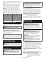
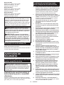
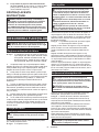
Router safety warnings
1. Hold the power tool by insulated gripping
surfaces only, because the cutter may contact
its own cord. Cutting a "live" wire may make
exposed metal parts of the power tool "live" and
could give the operator an electric shock.
2. Use clamps or another practical way to secure
and support the workpiece to a stable plat-
form. Holding the work by your hand or against
the body leaves it unstable and may lead to loss of
control.
3. The cutter bit shank must match the designed
collet chuck.
4. Only use a bit that is rated at least equal to the
maximum speed marked on the tool.
5. Wear hearing protection during extended
period of operation.
6. Handle the router bits very carefully.
7. Check the router bit carefully for cracks or
damage before operation. Replace cracked or
damaged bit immediately.
8. Avoid cutting nails. Inspect for and remove all
nails from the workpiece before operation.
9. Hold the tool rmly with both hands.
10. Keep hands away from rotating parts.
11. Make sure the router bit is not contacting the
workpiece before the switch is turned on.
12. Before using the tool on an actual workpiece,
let it run for a while. Watch for vibration or
wobbling that could indicate improperly
installed bit.
13. Be careful of the router bit rotating direction
and the feed direction.
14. Do not leave the tool running. Operate the tool
only when hand-held.
15. Always switch o and wait for the router bit to
come to a complete stop before removing the
tool from workpiece.
16. Do not touch the router bit immediately after
operation; it may be extremely hot and could
burn your skin.
17. Do not smear the tool base carelessly with
thinner, gasoline, oil or the like. They may
cause cracks in the tool base.
18. Some material contains chemicals which may
be toxic. Take caution to prevent dust inhala-
tion and skin contact. Follow material supplier
safety data.
19. Always use the correct dust mask/respirator
for the material and application you are work-
ing with.
20. Place the tool on stable area. Otherwise falling
accident may occur and cause an injury.
21. Keep cord away from your foot or any objects.
Otherwise an entangled cord may cause a falling
accident and result in personal injury.
SAVE THESE INSTRUCTIONS.
WARNING: DO NOT let comfort or familiarity
with product (gained from repeated use) replace
strict adherence to safety rules for the subject
product. MISUSE or failure to follow the safety
rules stated in this instruction manual may cause
serious personal injury.

11 ENGLISH
FUNCTIONAL
DESCRIPTION
CAUTION: Always be sure that the tool is
switched o and unplugged before adjusting or
checking function on the tool.
Adjusting the depth of cut
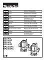
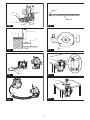
► Fig.1: 1. Lock lever 2. Adjusting hex bolt 3. Stopper
block 4. Adjusting knob 5. Depth pointer
6. Stopper pole 7. Stopper pole setting nut
8. Fast-feed button
1.
Place the tool on a at surface. Loosen the lock lever
and lower the tool body until the router bit just touches the at
surface. Tighten the lock lever to lock the tool body.
2. Turn the stopper pole setting nut counterclock-
wise. Lower the stopper pole until it makes contact
with the adjusting hex bolt. Align the depth pointer with
the "0" graduation. The depth of cut is indicated on the
scale by the depth pointer.
3. While pressing the fast-feed button, raise the
stopper pole until the desired depth of cut is obtained.
Minute depth adjustments can be obtained by turning
the adjusting knob (1 mm per turn).
4. By turning the stopper pole setting nut clockwise,
you can fasten the stopper pole rmly.
5. Now, your predetermined depth of cut can be
obtained by loosening the lock lever and then lowering
the tool body until the stopper pole makes contact with
the adjusting hex bolt of the stopper block.
Nylon nut
CAUTION: Do not lower the nylon nut too low.
The router bit will protrude dangerously.
The upper limit of the tool body can be adjusted by
turning the nylon nut.
► Fig.2: 1. Nylon nut
Stopper block
CAUTION: Since excessive cutting may cause
overload of the motor or diculty in controlling
the tool, the depth of cut should not be more than
15 mm at a pass when cutting grooves with an 8
mm diameter bit.
CAUTION: When cutting grooves with a 20
mm diameter bit, the depth of cut should not be
more than 5 mm at a pass.
CAUTION: For extra-deep grooving opera-
tions, make two or three passes with progres-
sively deeper bit settings.
As the stopper block has three adjusting hex bolts
which raise or lower 0.8 mm per turn, you can easily
obtain three dierent depths of cut without readjusting
the stopper pole.
► Fig.3: 1. Stopper pole 2. Adjusting hex bolt
3. Stopper block
Adjust the lowest adjusting hex bolt to obtain the deep-
est depth of cut, following the method of "Adjusting the
depth of cut".
Adjust the two remaining adjusting hex bolts to obtain
shallower depths of cut. The dierences in height of
these adjusting hex bolts are equal to the dierences in
depths of cut.
To adjust the adjusting hex bolts, turn the adjusting hex
bolts with a screwdriver or wrench. The stopper block is
also convenient for making three passes with progres-
sively deeper bit settings when cutting deep grooves.
Switch action
CAUTION: Before plugging in the tool, always
check to see that the switch trigger actuates
properly and returns to the "OFF" position when
released.
CAUTION: Make sure that the shaft lock is
released before the switch is turned on.
To prevent the switch trigger from being accidentally
pulled, a lock button is provided.
► Fig.4: 1. Lock button 2. Switch trigger
To start the tool, depress the lock button and pull the
switch trigger. Release the switch trigger to stop.
For continuous operation, depress the lock button fur-
ther while the switch trigger is being pulled.
To stop the tool, pull the switch trigger so that the lock
button returns automatically. Then release the switch
trigger.
After releasing the switch trigger, the lock-o function
works to prevent the switch trigger from being pulled.
CAUTION: Hold the tool rmly when turning
o the tool, to overcome the reaction.
Electronic function
The tool is equipped with the electronic functions for
easy operation.
Indication lamp
► Fig.5: 1. Indication lamp
The indication lamp lights up green when the tool is
plugged. If the indication lamp does not light up, the
mains cord or the controller may be defective. The indi-
cation lamp is lit but the tool does not start even if the
tool is switched on, the carbon brushes may be worn
out, or the controller, the motor or the ON/OFF switch
may be defective.
Unintentional restart proof
The tool does not start with the switch trigger pulled
even when the tool is plugged.
At this time, the indication lamp blinks in red and shows
the unintentional restart proof device is on function.
To cancel the unintentional restart proof, release the
switch trigger.
Soft start feature
Soft-start feature minimizes start-up shock, and makes
the tool start smoothly.

12 ENGLISH
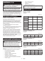
Constant speed control
Only for model RP2302FC, RP2303FC
Possible to get ne nish, because the rotating speed is
kept constant even under the loaded condition.
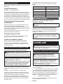
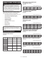
Speed adjusting dial
Only for model RP2302FC, RP2303FC
WARNING: Do not use the speed adjusting
dial during operation. The router bit can be touched
by the operator because of reaction force. This may
result in personal injury.
NOTICE: If the tool is operated continuously
at low speeds for a long time, the motor will get
overloaded, resulting in tool malfunction.
NOTICE: The speed adjusting dial can be turned
only as far as 6 and back to 1. Do not force it past
6 or 1, or the speed adjusting function may no
longer work.
The tool speed can be changed by turning the speed
adjusting dial to a given number setting from 1 to 6.
► Fig.6: 1. Speed adjusting dial
Higher speed is obtained when the dial is turned in the
direction of number 6. And lower speed is obtained
when it is turned in the direction of number 1.
This allows the ideal speed to be selected for optimum
material processing, i.e. the speed can be correctly
adjusted to suit the material and bit diameter.
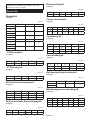
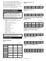
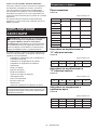
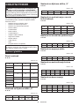
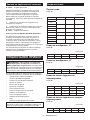
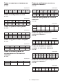
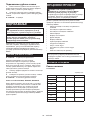
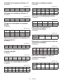
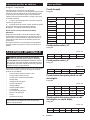
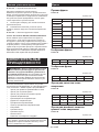
Refer to the table for the relationship between the num-
ber settings on the dial and the approximate tool speed.
Number min-1
19,000
211,000
314,000
417,000
520,000
623,000
Lighting up the lamps
Only for model RP1802F, RP1803F, RP2302FC,
RP2303FC
CAUTION: Do not look in the light or see the
source of light directly.
Pull the switch trigger to turn on the light. The lamp
keeps on lighting while the switch trigger is being pulled.
The lamp turns o approximately 10 seconds after
releasing the trigger.
► Fig.7: 1. Lamp
NOTE: Use a dry cloth to wipe the dirt o the lens of
the lamp. Be careful not to scratch the lens of lamp, or
it may lower the illumination.
ASSEMBLY
CAUTION: Always be sure that the tool is
switched o and unplugged before carrying out
any work on the tool.
Installing or removing the router bit
CAUTION: Install the router bit securely.
Always use only the wrench provided with the
tool. A loose or overtightened router bit can be
dangerous.
NOTICE: Do not tighten the collet nut without
inserting a router bit or install small shank bits
without using a collet sleeve. Either can lead to
breakage of the collet cone.
1. Insert the router bit all the way into the collet cone.
2.
Press the shaft lock to keep the shaft stationary and use
the wrench to tighten the collet nut securely. When using router
bits with smaller shank diameter, rst insert the appropriate
collet sleeve into the collet cone, then install the router bit.
► Fig.8: 1. Shaft lock 2. Wrench 3. Loosen 4. Tighten
To remove the router bit, follow the installation proce-
dure in reverse.
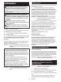
OPERATION
WARNING: Before operation, always make
sure that the stopper pole is secured rmly by the
stopper pole setting nut. Otherwise the depth of
cut may change during operation and cause personal
injury.
CAUTION: Before operation, always make
sure that the tool body automatically rises to
the upper limit and the router bit does not pro-
trude from the tool base when the lock lever is
loosened.
CAUTION: Always use both grips and rmly
hold the tool by both grips during operations.
CAUTION: Before operation, always make
sure that the chip deector is installed properly.
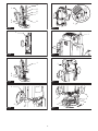
► Fig.9: 1. Chip deector
1. Set the base on the workpiece to be cut without
the router bit making any contact.
2.
Turn the tool on and wait until the router bit attains full speed.
3. Lower the tool body and move the tool forward
over the workpiece surface, keeping the base ush and
advancing smoothly until the cutting is complete.
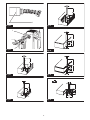
► Fig.10
When doing edge cutting, the workpiece surface should
be on the left side of the router bit in the feed direction.
► Fig.11: 1. Workpiece 2. Bit revolving direction
3. View from the top of the tool 4. Feed
direction

13 ENGLISH
NOTE: Moving the tool forward too fast may cause
a poor quality of cut, or damage to the router bit or
motor. Moving the tool forward too slowly may burn
and mar the cut. The proper feed rate will depend on
the router bit size, the kind of workpiece and depth
of cut.
Before beginning the cut on the actual workpiece, it
is advisable to make a sample cut on a piece of scrap
lumber. This will show exactly how the cut will look as
well as enable you to check dimensions.
NOTE: When using the straight guide or the trimmer
guide, be sure to install it on the right side in the feed
direction. This will help to keep it ush with the side of
the workpiece.
► Fig.12: 1. Feed direction 2. Bit revolving direction
3. Workpiece 4. Straight guide
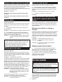
Straight guide
The straight guide is eectively used for straight cuts
when chamfering or grooving.
1. Install the straight guide on the guide holder using
the clamping screw (B). Insert the guide holder into the
holes in the tool base and tighten the clamping screw
(A). To adjust the distance between the router bit and
the straight guide, loosen the clamping screw (B) and
turn the ne adjusting screw (1.5 mm per turn). At the
desired distance, tighten the clamping screw (B) to
secure the straight guide in place.
► Fig.13: 1. Clamping screw (A) 2. Straight guide
3. Guide holder 4. Fine adjusting screw
5. Clamping screw (B)
2. When cutting, move the tool with the straight guide
ush with the side of the workpiece.
Wider straight guide of desired dimensions may be
made by using the convenient holes in the guide to bolt
on extra pieces of wood.
When using a large diameter router bit, attach pieces
of wood to the straight guide which have a thickness of
more than 15 mm (5/8″) to prevent the router bit from
striking the straight guide.
► Fig.14: 1. Straight guide 2. Wood
A=55 mm (2-3/16″)
B=55 mm (2-3/16″)
C=15 mm (5/8″) or thicker
If the distance between the side of the workpiece and the
cutting position is too wide for the straight guide, or if the
side of the workpiece is not straight, the straight guide
cannot be used. In this case, rmly clamp a straight board
to the workpiece and use it as a guide against the base.
Feed the tool in the direction of the arrow.
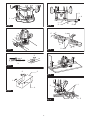
► Fig.15
Fine adjusting straight guide
Optional accessory
Insert the two rods into the outer mounting slots of the
guide holder, and secure them by tightening the two
clamping screws (B). Make sure that the thumb screw
(A) is tightened down, insert the two rods into the base,
and tighten the clamping screws (A).
► Fig.16: 1. Clamping screw (B) 2. Thumb screw (A)
3. Clamping screw (A)
Fine adjusting function for
positioning blade in relation to
straight guide
► Fig.17: 1. Thumb screw (A) 2. Thumb screw (B)
3. Scale ring
1. Loosen the thumb screw (A).
2. Turn the thumb screw (B) to adjust position (one
turn adjusts the position by 1 mm) as necessary.
3. Tighten the thumb screw (A) until it is secured.
Scale ring can be rotated separately, so scale unit can
be aligned to zero (0).
Adjusting guide shoe width
Loosen the screws marked by the circles to alter the
width of the straight guide. After altering width, tighten
the screws until they are secured.
Guide shoe width alteration range is 280 mm to 350
mm.
► Fig.18: 1. Screw
When set to minimum opening width
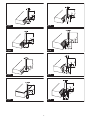
► Fig.19
When set to maximum opening width
► Fig.20
Templet guide
Optional accessory
The templet guide provides a sleeve through which the
router bit passes, allowing use of the router with templet
patterns.
► Fig.21
1. Pull the lock plate lever and insert the templet
guide.
► Fig.22: 1. Templet guide 2. Lock plate lever
2. Secure the templet to the workpiece. Place the
tool on the templet and move the tool with the templet
guide sliding along the side of the templet.
► Fig.23: 1. Router bit 2. Base 3. Base plate
4. Templet 5. Workpiece 6. Templet guide
NOTE: The workpiece will be cut a slightly dierent
size from the templet. Allow for the distance (X)
between the router bit and the outside of the templet
guide. The distance (X) can be calculated by using
the following equation:
Distance (X) = (outside diameter of the templet
guide - router bit diameter) / 2

14 ENGLISH
Trimmer guide
Optional accessory
Trimming, curved cuts in veneers for furniture and the
like can be done easily with the trimmer guide. The
guide roller rides the curve and assures a ne cut.
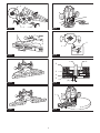
► Fig.24: 1. Trimmer guide
Install the trimmer guide on the guide holder using the
clamping screw (D). Insert the guide holder into the holes
in the tool base and tighten the clamping screw (A). To
adjust the distance between the router bit and the trimmer
guide, loosen the clamping screw (D) and turn the ne
adjusting screw (1.5 mm per turn). When adjusting the
guide roller up or down, loosen the clamping screw (C).
After adjusting, tighten all the clamping screws securely.
► Fig.25: 1. Guide holder 2. Fine adjusting screw
3. Clamping screw (D) 4. Clamping screw
(C) 5. Guide roller 6. Clamping screw (A)
When cutting, move the tool with the guide roller riding
the side of the workpiece.
► Fig.26: 1. Router bit 2. Guide roller 3. Workpiece
Dust nozzle sets
Use the dust nozzle for dust extraction.
1. Install the dust nozzle on the tool base using the
thumb screw so that protrusion on the dust nozzle t to
the notch in the tool base.
► Fig.27: 1. Dust nozzle 2. Thumb screw
2. Connect a vacuum cleaner to the dust nozzle.
► Fig.28
How to use screw M6 x 135 for
adjusting the depth of cut
When using the tool with a router table available in the
market, using this screw allows an operator to obtain
a small amount of adjustment of the depth of cut from
above the table.
Installing the screw with washer on
the tool
Insert the screw with washer through a screw hole on
the tool base and then screw in the threaded part of the
motor bracket of the tool. At this time, apply some grease
or lubricating oil to the inside of the screw hole on the tool
base and the threaded part of the motor bracket.
► Fig.29: 1. Flat washer 6 2. Screw M6 x 135
► Fig.30: 1. Screw M6 x 135 in a screw hole
► Fig.31: 1. Screw M6 x 135 2. Threaded part of the
motor bracket
Adjusting the depth of cut
1. A small amount of depth of cut can be obtained
by turning this screw with a screwdriver from above the
table. (1.0 mm per a full turn)
2. Turning the screw clockwise makes the depth
of cut greater and turning the screw counterclockwise
makes the depth of cut smaller.
► Fig.32: 1. Screwdriver
MAINTENANCE
CAUTION: Always be sure that the tool is
switched o and unplugged before attempting to
perform inspection or maintenance.
NOTICE: Never use gasoline, benzine, thinner,
alcohol or the like. Discoloration, deformation or
cracks may result.
To maintain product SAFETY and RELIABILITY,
repairs, any other maintenance or adjustment should
be performed by Makita Authorized or Factory Service
Centers, always using Makita replacement parts.
Replacing carbon brushes
► Fig.33: 1. Limit mark
Check the carbon brushes regularly.
Replace them when they wear down to the limit mark.
Keep the carbon brushes clean and free to slip in the
holders. Both carbon brushes should be replaced at the
same time. Use only identical carbon brushes.
1.
Use a screwdriver to remove the brush holder caps.
2. Take out the worn carbon brushes, insert the new
ones and secure the brush holder caps.
► Fig.34: 1. Brush holder cap
Only for model RP1803, RP1803F, RP2303FC
After replacing brushes, plug in the tool and break in
brushes by running tool with no load for about 10 min-
utes. Then check the tool while running and electric
brake operation when releasing the switch trigger.
If electric brake is not working well, ask your local
Makita service center for repair.
OPTIONAL ACCESSORIES
CAUTION: These accessories or attachments
are recommended for use with your Makita tool
specied in this manual. The use of any other
accessories or attachments might present a risk of
injury to persons. Only use accessory or attachment
for its stated purpose.
If you need any assistance for more details regarding
these accessories, ask your local Makita Service Center.
• Straight & groove forming bits
• Edge forming bits
• Laminate trimming bits
• Straight guide
• Trimmer guide
• Guide holder
• Templet guides
• Templet guide adapter
• Lock nut
• Collet cone
• Collet sleeve
• Wrench
• Dust nozzle set

15 ENGLISH
NOTE: Some items in the list may be included in the
tool package as standard accessories. They may
dier from country to country.
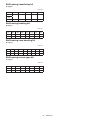
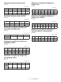
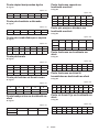
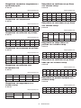
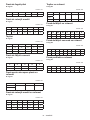
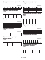
Router bits
Straight bit
► Fig.35
Unit:mm
D A L1 L2
620 50 15
1/4″
12 12 60 30
1/2″
12 10 60 25
1/2″
8 8 60 25
6 8 50 18
1/4″
6 6 50 18
1/4″
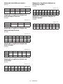
“U”Grooving bit
► Fig.36
Unit:mm
D A L1 L2 R
6 6 50 18 3
“V”Grooving bit
► Fig.37
Unit:mm
D A L1 L2 θ
1/4″ 20 50 15 90°
Drill point ush trimming bit
► Fig.38
Unit:mm
D A L1 L2 L3
12 12 60 20 35
8 8 60 20 35
6 6 60 18 28
Drill point double ush trimming bit
► Fig.39
Unit:mm
D A L1 L2 L3 L4
6 6 70 40 12 14
Board-jointing bit
► Fig.40
Unit:mm
DA1 A2 L1 L2 L3
12 38 27 61 420
Corner rounding bit
► Fig.41
Unit:mm
DA1 A2 L1 L2 L3 R
625 948 13 5 8
620 845 10 4 4
Chamfering bit
► Fig.42
Unit:mm
D A L1 L2 L3 θ
623 46 11 630°
620 50 13 545°
620 49 14 260°
Cove beading bit
► Fig.43
Unit:mm
D A L1 L2 R
620 43 8 4
625 48 13 8
Ball bearing ush trimming bit
► Fig.44
Unit:mm
D A L1 L2
610 50 20
1/4″
Ball bearing corner rounding bit
► Fig.45
Unit:mm
DA1 A2 L1 L2 L3 R
615 837 73.5 3
621 840 10 3.5 6
1/4″ 21 840 10 3.5 6

16 ENGLISH
Ball bearing chamfering bit
► Fig.46
Unit:mm
DA1 A2 L1 L2 θ
626 842 12 45°
1/4″
620 841 11 60°
Ball bearing beading bit
► Fig.47
Unit:mm
DA1 A2 A3 L1 L2 L3 R
620 12 840 10 5.5 4
626 12 842 12 4.5 7
Ball bearing cove beading bit
► Fig.48
Unit:mm
DA1 A2 A3 A4 L1 L2 L3 R
620 18 12 840 10 5.5 3
626 22 12 842 12 5 5
Ball bearing roman ogee bit
► Fig.49
Unit:mm
DA1 A2 L1 L2 L3 R1 R2
620 840 10 4.5 2.5 4.5
626 842 12 4.5 3 6

17 SLOVENŠČINA
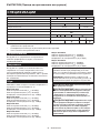
SLOVENŠČINA (Originalna navodila)
TEHNIČNI PODATKI
Model: RP1802
RP1802F
RP1803
RP1803F
RP2302FC RP2303FC
Zmogljivost vpenjalne glave 12 mm ali 1/2″
Zmogljivost ugreznjenja 0 – 70 mm
Hitrost brez obremenitve 23.000 min-1 22.000 min-1 9.000 – 23.000 min-1
Skupna višina 312 mm 327 mm
Neto teža 6,2 kg
Razred zaščite /II
Lučka - -
Gumb za izbiro hitrosti -
Električna zavora - -
•
Ker nenehno opravljamo raziskave in razvijamo svoje izdelke, se lahko tehnični podatki v tem dokumentu spremenijo brez obvestila.
• Tehnični podatki se lahko razlikujejo od države do države.
• Teža v skladu s postopkom EPTA 01/2014
Predvidena uporaba
Orodje je namenjeno za poravnano prirezovanje in
proliranje lesa, plastike in podobnih materialov.
Priključitev na električno omrežje
Napetost električnega omrežja se mora ujemati s
podatki na tipski ploščici. Stroj deluje samo z enofazno
izmenično napetostjo. Stroj je po evropskih smernicah
dvojno zaščitno izoliran, zato se ga lahko priključi tudi v
vtičnice brez ozemljitvenega voda.
Hrup
Običajna A-ovrednotena raven hrupa v skladu z EN62841-2-17:
Model RP1802
Raven zvočnega tlaka (LpA): 85 dB (A)
Raven zvočne moči (LWA): 96 dB (A)
Odstopanje (K): 3 dB (A)
Model RP1802F
Raven zvočnega tlaka (LpA): 85 dB (A)
Raven zvočne moči (LWA): 96 dB (A)
Odstopanje (K): 3 dB (A)
Model RP1803
Raven zvočnega tlaka (LpA): 85 dB (A)
Raven zvočne moči (LWA): 96 dB (A)
Odstopanje (K): 3 dB (A)
Model RP1803F
Raven zvočnega tlaka (LpA): 85 dB (A)
Raven zvočne moči (LWA): 96 dB (A)
Odstopanje (K): 3 dB (A)
Model RP2302FC
Raven zvočnega tlaka (LpA): 88 dB(A)
Raven zvočne moči (LWA): 99 dB (A)
Odstopanje (K): 3 dB(A)
Model RP2303FC
Raven zvočnega tlaka (LpA): 88 dB(A)
Raven zvočne moči (LWA): 99 dB (A)
Odstopanje (K): 3 dB(A)
OPOMBA: Navedene vrednosti oddajanja hrupa so
bile izmerjene v skladu s standardnimi metodami
testiranja in se lahko uporabljajo za primerjavo orodij.
OPOMBA: Navedene vrednosti oddajanja hrupa
se lahko uporabljajo tudi pri predhodni oceni
izpostavljenosti.
OPOZORILO: Uporabljajte zaščito za sluh.
OPOZORILO: Oddajanje hrupa med dejansko
uporabo električnega orodja se lahko razlikuje od
navedenih vrednosti, odvisno od načina uporabe
orodja in predvsem vrste obdelovanca.
OPOZORILO: Upravljavec mora za lastno
zaščito poznati varnostne ukrepe, ki temeljijo
na oceni izpostavljenosti v dejanskih pogojih
uporabe (poleg časa proženja je treba upoštevati
celoten delovni cikel, vključno s časom, ko je
orodje izklopljeno, in časom, ko deluje v prostem
teku).
Vibracije
Skupne vrednosti vibracij (vektorska vsota treh osi) v
skladu z EN62841-2-17:
Model RP1802
Delovni način: rezanje utorov v plošče MDF
Emisije vibracij (ah): 5,1 m/s2
Odstopanje (K): 1,5 m/s2
Model RP1802F
Delovni način: rezanje utorov v plošče MDF
Emisije vibracij (ah): 5,1 m/s2
Odstopanje (K): 1,5 m/s2
Model RP1803
Delovni način: rezanje utorov v plošče MDF
Emisije vibracij (ah): 5,1 m/s2
Odstopanje (K): 1,5 m/s2

18 SLOVENŠČINA
Model RP1803F
Delovni način: rezanje utorov v plošče MDF
Emisije vibracij (ah): 5,1 m/s2
Odstopanje (K): 1,5 m/s2
Model RP2302FC
Delovni način: rezanje utorov v plošče MDF
Emisije vibracij (ah): 4,2 m/s2
Odstopanje (K): 1,5 m/s2
Model RP2303FC
Delovni način: rezanje utorov v plošče MDF
Emisije vibracij (ah): 4,2 m/s2
Odstopanje (K): 1,5 m/s2
OPOMBA: Navedene skupne vrednosti oddajanja
vibracij so bile izmerjene v skladu s standardnimi
metodami testiranja in se lahko uporabljajo za primer-
javo orodij.
OPOMBA: Navedene skupne vrednosti oddajanja
vibracij se lahko uporabljajo tudi pri predhodni oceni
izpostavljenosti.
OPOZORILO: Oddajanje vibracij med
dejansko uporabo električnega orodja se lahko
razlikuje od navedenih vrednosti, odvisno
od načina uporabe orodja in predvsem vrste
obdelovanca.
OPOZORILO: Upravljavec mora za lastno
zaščito poznati varnostne ukrepe, ki temeljijo
na oceni izpostavljenosti v dejanskih pogojih
uporabe (poleg časa proženja je treba upoštevati
celoten delovni cikel, vključno s časom, ko je
orodje izklopljeno, in časom, ko deluje v prostem
teku).
Izjava o skladnosti ES
Samo za evropske države
Izjava ES o skladnosti je vključena v dodatku A, ki je
priložen tem navodilom za uporabo.
VARNOSTNA
OPOZORILA
Splošna varnostna opozorila za
električno orodje
OPOZORILO: Preberite vsa varnostna opo-
zorila in navodila s slikami in tehničnimi podatki,
ki so dobavljeni skupaj z električnim orodjem.
Ob neupoštevanju spodaj navedenih navodil obstaja
nevarnost električnega udara, požara in/ali hudih
telesnih poškodb.
Shranite vsa opozorila in navo-
dila za poznejšo uporabo.
Izraz „električno orodje“ v opozorilih se nanaša na vaše
električno orodje (s kablom) ali baterijsko električno
orodje (brez kabla).
Varnostna opozorila pri uporabi
rezkarja
1. Držite električno orodje na izoliranih držalnih
površinah, saj lahko pride rezalnik v stik z
lastnim kablom. Ob stiku z vodniki pod nape-
tostjo dobijo napetost vsi neizolirani kovinski deli
električnega orodja, zaradi česar lahko uporabnik
utrpi električni udar.
2. Uporabljajte sponke ali druge praktične načine
za pritrditev in podporo obdelovanca na sta-
bilno podlago. Če držite obdelovanca z roko
ali ga naslanjate na telo, je nestabilen in lahko
povzroči izgubo nadzora.
3. Vpenjalni nastavek rezalnika se mora prilegati
zasnovani vpenjalni glavi.
4. Uporabljajte le nastavek, ki je ocenjen za
vsaj enako največjo hitrost, ki je označena na
orodju.
5. Med daljšo uporabo uporabljajte zaščito za
sluh.
6. Z nastavki rezkarja ravnajte zelo previdno.
7. Pred uporabo skrbno preverite nastavek rez-
karja glede obrabe, razpok ali poškodb. Takoj
zamenjajte počen ali poškodovan nastavek.
8. Izogibajte se rezanju žebljev. Pred delom poi-
ščite in odstranite vse žeblje iz obdelovanca.
9. Orodje trdno držite z obema rokama.
10. Ne približujte rok vrtečim se delom.
11. Preden vklopite stikalo, se prepričajte, ali se
nastavek rezkarja ne dotika obdelovanca.
12. Pred začetkom dela na obdelovancu pustite
orodje delovati nekaj časa v prostem teku.
Bodite pozorni na vibracije ali majanje, ki
bi lahko kazalo na nepravilno nameščen
nastavek.
13. Bodite pozorni na smer vrtenja nastavka rez-
karja in smer pomika.
14. Orodja ne pustite delovati brez nadzora.
Dovoljeno ga je uporabljati samo ročno.
15. Orodje vedno izključite in počakajte, da se
nastavek rezkarja popolnoma ustavi, preden
ga odstranite iz obdelovanca.
16. Takoj po končani obdelavi se ne dotikajte
nastavka rezkarja; ta je lahko zelo vroč in
lahko povzroči opekline kože.
17. Drsnika orodja ne mažite brezbrižno z razred-
čilom, bencinom, oljem ali podobnimi sredstvi.
To lahko povzroči razpoke v drsniku orodja.
18. Nekateri materiali vsebujejo kemikalije, ki so
lahko strupene. Bodite previdni ter preprečite
vdihavanje prahu in stik s kožo. Upoštevajte
varnostne podatke dobavitelja materiala.
19. Vedno uporabite ustrezno protiprašno masko/
respirator za načrtovani material in uporabo.
20. Orodje položite na stabilno mesto. V naspro-
tnem primeru lahko orodje pade in povzroči
poškodbe.
21. Kabla ne približujte stopalu ali katerimkoli
predmetom. Sicer lahko zaradi prepletenega
kabla pride do nesreče ali poškodbe.
SHRANITE TA NAVODILA.

19 SLOVENŠČINA
OPOZORILO: NE dovolite, da bi zaradi udob-
nejšega dela ali znanja o uporabi izdelka (prido-
bljenega z večkratno uporabo) opustili strogo
upoštevanje varnostnih zahtev v okviru pravilne
uporabe orodja. ZLORABA ali neupoštevanje var-
nostnih zahtev v teh navodilih za uporabo lahko
povzroči resne telesne poškodbe.
OPIS DELOVANJA
POZOR: Pred vsako nastavitvijo ali pregle-
dom nastavitev orodja se prepričajte, da je orodje
izklopljeno in izključeno z električnega omrežja.
Nastavitev globine rezanja
► Sl.1: 1. Zaklepna ročica 2. Nastavitveni šes-
trobi sornik 3. Omejevalnik 4. Nastavitveni
gumb 5. Kazalec globine 6. Ustavljalni drog
7. Nastavitvena matica ustavljalnega droga
8. Gumb za hitro podajanje
1. Orodje položite na ravno podlago. Sprostite zakle-
pno ročico in spustite ohišje orodja, da se nastavek rez-
karja dotakne ravne podlage. Privijte zaklepno ročico, ki
preprečuje premikanje orodja.
2. Obrnite nastavitveno matico ustavljalnega droga
v nasprotni smeri urinega kazalca. Spustite omejevalni
drog do te mere, da se dotika nastavitvenega šestro-
bega sornika. Poravnajte kazalec globine na oznako
„0“. Globino reza označuje kazalec globine na skali.
3. Medtem ko pritiskate gumb za hitro podajanje,
dvignite ustavljalni drog, da dosežete želeno globino.
Prilagoditev minimalne globine lahko dosežete z vrte-
njem nastavljalnega gumba (1 mm na obrat).
4. Z vrtenjem nastavitvene matice ustavljalnega
droga v smeri urinega kazalca, lahko trdno pritrdite
ustavljalni drog.
5. Zdaj lahko dosežete prednastavljeno globino reza,
tako da popustite zaklepno ročico in spustite ohišje
orodja, da se ustavljalni drog dotakne nastavljalnega
šestrobnega vijaka omejevalnika.
Najlonska matica
POZOR: Najlonske matice ne spuščajte
prenizko. Nastavek rezkarja bo nevarno prebil
površino.
Zgornje omejevalo telesa orodja lahko prilagodite z
vrtenjem najlonske matice.
► Sl.2: 1. Najlonska matica
Omejevalnik
POZOR: Dolgotrajno rezkanje lahko preobre-
meni motor in povzroči težave z vodenjem orodja,
zato pri izdelavi utorov z nastavki premera 8 mm
pazite, da nastavljena globina reza ne bo večja od
15 mm na delovni korak.
POZOR: Pri izdelavi utorov z 20 mm širokim
rezkarjem naj globina reza ne presega 5 mm na
delovni korak.
POZOR: Za rezanje izjemno globokih utorov
izvedite dva ali tri delovne korake s postopnim
povečevanjem globine reza.
Omejevalnik ima tri nastavitvene šestrobe vijake, ki
se dvigajo oz. spuščajo 0,8 mm na obrat, zato lahko
enostavno nastavite tri različne globine reza, ne da bi
prilagajali drog ustavljala.
► Sl.3: 1. Drog ustavljala 2. Nastavitveni šestrobi
sornik 3. Omejevalnik
Najnižji nastavitveni šestrobi sornik nastavite na najve-
čjo globino reza, kot je opisano v razdelku „Nastavitev
globine rezanja“.
Druga dva nastavitvena šestroba sornika nastavite na
manjšo globino reza. Razlike v višini teh nastavitvenih
šestrobih sornikov so enake razlikam v globini reza.
Da bi prilagodili nastavitvene šestrobe sornike, jih obr-
nite z izvijačem ali ključem. Omejevalnik je priporočljivo
uporabljati tudi za izdelovanje globokih utorov v treh
delovnih korakih s postopnim povečanjem globine reza.
Delovanje stikala
POZOR: Pred priključitvijo orodja v električno
omrežje se vedno prepričajte, da sprožilno stikalo
deluje brezhibno in se vrača v položaj za izklop,
ko ga spustite.
POZOR: Preden vklopite stikalo, se prepri-
čajte, ali je blokada osi sproščena.
Za preprečevanje nenamerne sprožitve stikala je name-
ščen gumb za zaklep.
► Sl.4: 1. Gumb za zaklep 2. Sprožilec
Za zagon orodja hkrati pritisnite na gumb za zaklep in
sprožilno stikalo. Če želite zaustaviti orodje, spustite
sprožilec.
Za neprekinjeno delovanje dodatno pritisnite na gumb
za zaklep, medtem ko držite sprožilec.
Za ustavitev orodja povlecite sprožilno stikalo, da se
gumb za zaklep samodejno vrne v prvotni položaj. Nato
spustite sprožilec.
Ko spustite sprožilno stikalo, deluje funkcija zaklepa, da
prepreči premik sprožilnega stikala.
POZOR: Med izklopom trdno držite orodje, da
obvladate reakcijo.

20 SLOVENŠČINA
Elektronska funkcija
Orodje je opremljeno z elektronskimi funkcijami za
enostavno delovanje.
Kontrolna lučka
► Sl.5: 1. Kontrolna lučka
Zelena kontrolna lučka se vklopi, ko orodje priključite na
električno omrežje. Če se kontrolna lučka ne vklopi, sta
lahko okvarjena napajalni kabel ali elektronsko vezje.
Če kontrolna lučka sveti in je stikalo v položaju za vklop,
vendar se orodje ne zažene, sta karbonski krtački izrab-
ljeni ali pa je prišlo do okvare motorja oziroma vklopno-
-izklopnega stikala.
Zaščita pred nenamernim vklopom
Orodje se ne vklopi, ko pritisnete na sprožilec, čeprav je
orodje priključeno v električno omrežje.
V takšnem primeru kontrolna lučka utripa rdeče in
sporoča, da se je zagnala funkcija za zaščito pred
nenamernim vklopom.
Za izklop funkcije za zaščito pred nenamernim vklopom
sprostite sprožilec.
Funkcija mehkega zagona
Funkcija mehkega zagona zmanjša sunek ob zagonu in
omogoči gladek zagon orodja.
Nadzor stalne hitrosti
Samo za modela RP2302FC, RP2303FC
Možnost ne končne obdelave, ker hitrost ostane
nespremenjena kljub povečani obremenitvi med delom.
Gumb za izbiro hitrosti
Samo za modela RP2302FC, RP2303FC
OPOZORILO: Med delovanjem ne upo-
rabljajte gumba za izbiro hitrosti. Uporabnik se
lahko dotakne nastavka rezkarja zaradi reakcijske
sile. To lahko povzroči telesne poškodbe.
OBVESTILO: Če stroj dalj časa neprekinjeno
deluje z nizkim številom vrtljajev, pride do čez-
merne obremenitve motorja in morebitne okvare
stroja.
OBVESTILO: Gumb za izbiro hitrosti lahko obr-
nete samo do 6 in nazaj do 1. Ne vrtite ga na silo
prek položajev 6 ali 1, ker lahko pride do okvare
funkcije nastavljanja hitrosti.
Hitrost orodja lahko spreminjate, tako da obračate
gumb za izbiro hitrosti na določeno številko od 1 do 6.
► Sl.6: 1. Gumb za izbiro hitrosti
Višjo hitrost dosežete, kadar gumb obrnete v smeri
številke 6. Nižjo hitrost pa dobite, če številčnico obrnete
v smeri številke 1.
To omogoča izbiro idealen hitrosti za optimalno obde-
lavo materiala, torej lahko hitrost pravilno nastavite, da
ustreza materialu in premeru nastavka.
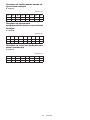
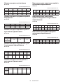
Glejte tabelo za razmerje med nastavitvijo vrednosti na
gumbu in približno hitrostjo orodja.
Številka min-1
19.000
211.000
314.000
417.000
520.000
623.000
Vklop lučk
Samo za modele RP1802F, RP1803F, RP2302FC,
RP2303FC
POZOR: Ne glejte neposredno v lučko ali vir
svetlobe.
Povlecite sprožilno stikalo za vklop lučke. Lučka sveti,
dokler je pritisnjen sprožilec. Svetilka ugasne približno
10 sekund zatem, ko spustite sprožilnik.
► Sl.7: 1. Lučka
OPOMBA: Uporabite suho krpo, da obrišete umaza-
nijo z leče lučke. Pazite, da ne opraskate stekla lučke,
ker praske občutno zmanjšajo svetilnost.
MONTAŽA
POZOR: Pred vsakim posegom v orodje se
prepričajte, da je orodje izklopljeno in izključeno z
električnega omrežja.
Nameščanje ali odstranjevanje
nastavka rezkarja
POZOR: Trdno namestite nastavek rezkarja.
Vedno uporabljajte ključ, ki je priložen orodju.
Ohlapno ali premočno zategnjeni nastavki rezkarja so
lahko nevarni.
OBVESTILO: Ne zategujte vpenjalne matice brez
vstavljanja nastavka rezkarja in ne nameščajte
nastavkov z majhnim osnim premerom brez upo-
rabe vpenjalnega adapterja. Oboje lahko povzroči
zlom vpenjalnega stožca.
1. Nastavek rezkarja do konca vstavite v vpenjalni
stožec.
2. Pritisnite zaporo vretena, da pritrdite vreteno in
uporabite ključ, da trdno zategnete vpenjalno matico.
Kadar uporabljate nastavke rezkarja z manjšim osnim
premerom, najprej vstavite ustrezni vpenjalni adapter v
vpenjalni stožec, nato pa namestite nastavek rezkarja.
► Sl.8: 1. Zapora vretena 2. Ključ 3. Popustite
4. Zategnite
Za odstranjevanje nastavka rezkarja izvedite postopek
namestitve v obratnem vrstnem redu.
Pagina se încarcă...
Pagina se încarcă...
Pagina se încarcă...
Pagina se încarcă...
Pagina se încarcă...
Pagina se încarcă...
Pagina se încarcă...
Pagina se încarcă...
Pagina se încarcă...
Pagina se încarcă...
Pagina se încarcă...
Pagina se încarcă...
Pagina se încarcă...
Pagina se încarcă...
Pagina se încarcă...
Pagina se încarcă...
Pagina se încarcă...
Pagina se încarcă...
Pagina se încarcă...
Pagina se încarcă...
Pagina se încarcă...
Pagina se încarcă...
Pagina se încarcă...
Pagina se încarcă...
Pagina se încarcă...
Pagina se încarcă...
Pagina se încarcă...
Pagina se încarcă...
Pagina se încarcă...
Pagina se încarcă...
Pagina se încarcă...
Pagina se încarcă...
Pagina se încarcă...
Pagina se încarcă...
Pagina se încarcă...
Pagina se încarcă...
Pagina se încarcă...
Pagina se încarcă...
Pagina se încarcă...
Pagina se încarcă...
Pagina se încarcă...
Pagina se încarcă...
Pagina se încarcă...
Pagina se încarcă...
Pagina se încarcă...
Pagina se încarcă...
Pagina se încarcă...
Pagina se încarcă...
Pagina se încarcă...
Pagina se încarcă...
Pagina se încarcă...
Pagina se încarcă...
Pagina se încarcă...
Pagina se încarcă...
Pagina se încarcă...
Pagina se încarcă...
Pagina se încarcă...
Pagina se încarcă...
Pagina se încarcă...
Pagina se încarcă...
Pagina se încarcă...
Pagina se încarcă...
Pagina se încarcă...
Pagina se încarcă...
Pagina se încarcă...
Pagina se încarcă...
Pagina se încarcă...
Pagina se încarcă...
Pagina se încarcă...
Pagina se încarcă...
Pagina se încarcă...
Pagina se încarcă...
Pagina se încarcă...
Pagina se încarcă...
Pagina se încarcă...
Pagina se încarcă...
-
 1
1
-
 2
2
-
 3
3
-
 4
4
-
 5
5
-
 6
6
-
 7
7
-
 8
8
-
 9
9
-
 10
10
-
 11
11
-
 12
12
-
 13
13
-
 14
14
-
 15
15
-
 16
16
-
 17
17
-
 18
18
-
 19
19
-
 20
20
-
 21
21
-
 22
22
-
 23
23
-
 24
24
-
 25
25
-
 26
26
-
 27
27
-
 28
28
-
 29
29
-
 30
30
-
 31
31
-
 32
32
-
 33
33
-
 34
34
-
 35
35
-
 36
36
-
 37
37
-
 38
38
-
 39
39
-
 40
40
-
 41
41
-
 42
42
-
 43
43
-
 44
44
-
 45
45
-
 46
46
-
 47
47
-
 48
48
-
 49
49
-
 50
50
-
 51
51
-
 52
52
-
 53
53
-
 54
54
-
 55
55
-
 56
56
-
 57
57
-
 58
58
-
 59
59
-
 60
60
-
 61
61
-
 62
62
-
 63
63
-
 64
64
-
 65
65
-
 66
66
-
 67
67
-
 68
68
-
 69
69
-
 70
70
-
 71
71
-
 72
72
-
 73
73
-
 74
74
-
 75
75
-
 76
76
-
 77
77
-
 78
78
-
 79
79
-
 80
80
-
 81
81
-
 82
82
-
 83
83
-
 84
84
-
 85
85
-
 86
86
-
 87
87
-
 88
88
-
 89
89
-
 90
90
-
 91
91
-
 92
92
-
 93
93
-
 94
94
-
 95
95
-
 96
96


