Makita DUN600L Manual de utilizare
- Categorie
- Aparate de tuns gard viu
- Tip
- Manual de utilizare

DUN500W
DUN600L
EN Cordless Pole Hedge Trimmer INSTRUCTION MANUAL 9
PL Akumulatorowe Nożyce Do
Żywopłotu Na Wysięgniku INSTRUKCJA OBSŁUGI 19
HU Akkumulátoros nyeles
sövénynyíró HASZNÁLATI KÉZIKÖNYV 30
SK Akumulátorový tyčový
plotostrih NÁVOD NA OBSLUHU 41
CS Akumulátorový plotostřih na
tyči NÁVOD K OBSLUZE 52
UK
Акумуляторна штангова
пила для підрізання
живоплоту
ІНСТРУКЦІЯ З
ЕКСПЛУАТАЦІЇ 62
RO Maşină de tuns gardul viu
înalt cu acumulator MANUAL DE INSTRUCŢIUNI 74
DE Akku-Heckenschneider BETRIEBSANLEITUNG 85

DUN600L
DUN500W
6
7
8
9
3
4
5
1
14
4
5
6
7
9
1
2
10 11
13 12
Fig.1
1 2
3
Fig.2
1
2
Fig.3
2

1
2
Fig.4
1
2
Fig.5
1
2
Fig.6
1
2
Fig.7
1
2
Fig.8
1
2
Fig.9
1
2
3
4
5
Fig.10
1
Fig.11
3

2
1
3
4
Fig.12
1
2
Fig.13
1
34
2
Fig.14
Fig.15
1
2
Fig.16
1
1
Fig.17
1
Fig.18
4

2
1
4
3
Fig.19
1
2
Fig.20
2
3
1
Fig.21
1
2
3
Fig.22
1
2
Fig.23
1
2
Fig.24
Fig.25
5

1
2
Fig.26
Fig.27
1
Fig.28
(1)
(2)
Fig.29
Fig.30
Fig.31
15 m
Fig.32
15 m
Fig.33
6

15 m
Fig.34
15 m
Fig.35
Fig.36
Fig.37
Fig.38
1
2
Fig.39
1
2
Fig.40
1
Fig.41
7

1
Fig.42
21
Fig.43
8

9ENGLISH
ENGLISH (Original instructions)
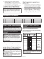
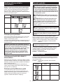
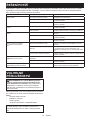
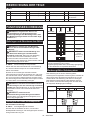
SPECIFICATIONS
Model: DUN500W DUN600L
Blade length 500 mm 600 mm
Strokes per minute 2,000 / 3,600 / 4,400 min-1
Cutting blade angle 115° (up 45°, down 70°) –
Overall length 2,115 mm 2,050 mm
Rated voltage D.C. 18 V
Net weight 3.9 - 4.3 kg 3.7 - 4.1 kg
• Duetoourcontinuingprogramofresearchanddevelopment,thespecicationshereinaresubjecttochange
without notice.
• Specicationsmaydierfromcountrytocountry.
• Theweightmaydierdependingontheattachment(s),includingthebatterycartridge.Thelightestandheavi-
est combination, according to EPTA-Procedure 01/2014, are shown in the table.
Applicable battery cartridge and charger
Batterycartridge BL1815N / BL1820 / BL1820B / BL1830 / BL1830B / BL1840 /
BL1840B / BL1850 / BL1850B / BL1860B
Charger DC18RC / DC18RD / DC18RE / DC18SD / DC18SE / DC18SF /
DC18SH
• Someofthebatterycartridgesandchargerslistedabovemaynotbeavailabledependingonyourregionof
residence.
WARNING: Only use the battery cartridges and chargers listed above.Useofanyotherbatterycartridges
andchargersmaycauseinjuryand/orre.
Recommended battery adapter
Batteryadapter PDC01
• Thebatteryadapter(s)listedabovemaynotbeavailabledependingonyourregionofresidence.
• Beforeusingthebatteryadapter,readinstructionandcautionarymarkingsonthebatteryadapter.
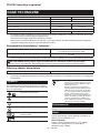
Symbols
Thefollowingsshowthesymbolsusedfortheequip-
ment.Besurethatyouunderstandtheirmeaningbefore
use.
Read instruction manual.
Do not expose to moisture.
Wear a helmet, goggles and ear protection.
Beware of pinching.
Beware of electrical lines, risk of electrical
shock.
Keep distance at least 15 m.
Ni-MH
Li-ion
OnlyforEUcountries
Donotdisposeofelectricequipmentor
batterypacktogetherwithhouseholdwaste
material!
In observance of the European Directives,
on Waste Electric and Electronic
EquipmentandBatteriesandAccumulators
and Waste Batteries and Accumulators
and their implementation in accordance
withnationallaws,electricequipmentand
batteriesandbatterypack(s)thathave
reached the end of their life must be col-
lectedseparatelyandreturnedtoanenvi-
ronmentallycompatiblerecyclingfacility.
Intended use
The tool is intended for trimming hedges.
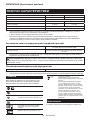
Noise
ThetypicalA-weightednoiseleveldeterminedaccord-
ing to EN62841-4-2:
Model DUN500W
Sound pressure level (LpA) : 81.5 dB(A)
Sound power level (LWA) : 92.5 dB (A)
Uncertainty(K):3dB(A)

10 ENGLISH
Model DUN600L
Sound pressure level (LpA) : 82.5 dB(A)
Sound power level (LWA) : 93.5 dB (A)
Uncertainty(K):3dB(A)
NOTE: The declared noise emission value(s) has
been measured in accordance with a standard test
methodandmaybeusedforcomparingonetoolwith
another.
NOTE: The declared noise emission value(s)
mayalsobeusedinapreliminaryassessmentof
exposure.
WARNING: Wear ear protection.
WARNING:
The noise emission during actual
use of the power tool can dier from the declared
value(s) depending on the ways in which the tool is
used especially what kind of workpiece is processed.
WARNING:
Be sure to identify safety measures
to protect the operator that are based on an estima-
tion of exposure in the actual conditions of use (tak-
ing account of all parts of the operating cycle such
as the times when the tool is switched o and when
it is running idle in addition to the trigger time).
Vibration
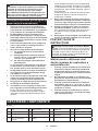
Applicable standard : EN62841-4-2
Model Left hand (Front grip / Handle) Right hand (Rear grip)
ah (m/s2)UncertaintyK
(m/s2)
ah (m/s2)UncertaintyK
(m/s2)
DUN500W 4.7 1.5 2.5 m/s2 or
less
1.5
DUN600L 3.8 1.5 2.7 1.5
NOTE: The declared vibration total value(s) has been measured in accordance with a standard test method and
maybeusedforcomparingonetoolwithanother.
NOTE:Thedeclaredvibrationtotalvalue(s)mayalsobeusedinapreliminaryassessmentofexposure.
WARNING: The vibration emission during actual use of the power tool can dier from the declared
value(s) depending on the ways in which the tool is used especially what kind of workpiece is processed.
WARNING: Be sure to identify safety measures to protect the operator that are based on an estimation
of exposure in the actual conditions of use (taking account of all parts of the operating cycle such as the
times when the tool is switched o and when it is running idle in addition to the trigger time).
EC Declaration of Conformity
For European countries only
TheECdeclarationofconformityisincludedasAnnexA
to this instruction manual.
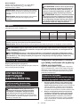
SAFETY WARNINGS
General power tool safety warnings
WARNING: Read all safety warnings, instruc-
tions, illustrations and specications provided
with this power tool. Failure to follow all instructions
listedbelowmayresultinelectricshock,reand/or
seriousinjury.
Save all warnings and instruc-
tions for future reference.
Theterm"powertool"inthewarningsreferstoyour
mains-operated(corded)powertoolorbattery-operated
(cordless) power tool.
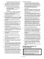
Cordless Pole Hedge Trimmer
Safety Warnings
1. Keep all parts of the body away from the blade.
Do not remove cut material or hold material
to be cut when blades are moving. Blades
continuetomoveaftertheswitchisturnedo.A
moment of inattention while operating the hedge
trimmermayresultinseriouspersonalinjury.
2. Carry the hedge trimmer by the handle with the
blade stopped and taking care not to operate
any power switch.Propercarryingofthehedge
trimmer will decrease the risk of inadvertent start-
ingandresultantpersonalinjuryfromtheblades.
3. When transporting or storing the hedge trim-
mer, always t the blade cover. Proper handling
of the hedge trimmer will decrease the risk of
personalinjuryfromtheblades.
4.
When clearing jammed material or servicing the unit,
make sure all power switches are o and the battery
pack is removed or disconnected. Unexpected actua-
tionofthehedgetrimmerwhileclearingjammedmaterial
orservicingmayresultinseriouspersonalinjury.
5. Hold the hedge trimmer by insulated gripping
surfaces only, because the blade may contact
hidden wiring. Blades contacting a "live" wire
maymakeexposedmetalpartsofthehedgetrim-
mer "live" and could give the operator an electric
shock.

11 ENGLISH
6. Keep all power cords and cables away from
cutting area.Powercordsorcablesmaybehid-
deninhedgesorbushesandcanbeaccidentally
cutbytheblade.
7. Do not use the hedge trimmer in bad weather
conditions, especially when there is a risk of
lightning. This decreases the risk of being struck
bylightning.
8. To reduce the risk of electrocution, never use
the pole hedge trimmer near any electrical
power lines. Contact with or use near power lines
maycauseseriousinjuryorelectricshockresult-
ing in death.
9. Always use two hands when operating the pole
hedge trimmer. Hold the pole hedge trimmer with
both hands to avoid loss of control.
10. Always use head protection when operating
the pole hedge trimmer overhead. Falling debris
canresultinseriouspersonalinjury.
Additional Safety Instructions
Preparation
1. THIS HEDGE TRIMMER CAN CAUSE SERIOUS
INJURIES. Read the instructions carefully
for the correct handling, preparation, main-
tenance, starting and stopping of the tool.
Become familiar with all controls and the
proper use of the tool.
2. Check the hedges and bushes for foreign
objects, such as wire fences or hidden wiring
before operating the tool.
3. The tool must not be used by children or
young persons under 18 years of age. Young
personsover16yearsofagemaybeexempted
fromthisrestrictioniftheyareundergoingtraining
under the supervision of an expert.
4. In the event of an emergency, switch o
the tool and remove the battery cartridge
immediately.
5. DANGER - Keep hands away from blade.
Contact with blade will result in serious personal
injury.
6. Only use with handle and guard properly
assembled to the tool. The use of the tool
withouttheproperguardorhandleprovidedmay
resultinseriouspersonalinjury.
7. First-time users should have an experienced
user show them how to use the tool.
8. Before operation, examine the work area for
wire fences, stones, or other solid objects.
They can damage the blades.
9.
Use the tool only if you are in good physical
condition.Ifyouaretired,yourattentionwillbe
reduced.Beespeciallycarefulattheendofawork-
ingday.Performallworkcalmlyandcarefully.The
user is responsible for all damages to third parties.
10. Before starting work, check to make sure that
the tool is in good and safe working order.
Ensure guards are tted properly. The tool
must not be used unless fully assembled.
11. Avoid dangerous environment. Don't use the
tool in damp or wet locations or expose it to
rain. Water entering the tool will increase the
risk of electric shock.
Personal protective equipment
1. Work gloves of stout leather are part of the
basic equipment of the tool and must always
be worn when working with it. Also wear
sturdy shoes with anti-skid soles.
2. Wear ear protection such as ear mus to pre-
vent hearing loss.
3. Wear protective goggles, safety helmet and
protective gloves to protect yourself from
ying debris or falling objects.
4. When touching blades or adjusting the blade
angle, wear protective gloves. Blades can cut
barehandsseverely.
Operation
1. Always use two hands to operate the tool tted
with two handles. Using one hand could cause
lossofcontrolandresultinseriouspersonalinjury.
2.
While operating the tool, always ensure that the oper-
ating position is safe and secure. Overreaching with
the tool, particularly from a ladder, is extremely dan-
gerous. Do not work from anything wobbly or inrm.
3.
Do not simultaneously wear multiple belt harnesses
and/or shoulder harnesses when operating the tool.
4. During operation, keep bystanders or animals
at least 15 m away from the tool. Stop the tool
as soon as someone approaches.
5. If cutting tool strikes any object or the tool
starts making unusual noise or vibration,
switch o the tool and remove the battery car-
tridge immediately and allow the tool to stop.
And then take the following steps:
• inspect for damage
• check for, and tighten, any loose parts
• have any damaged parts replaced or
repaired with genuine spare parts.
6. Only use the tool for its intended purpose. Do
not use the tool for any other purpose.
7. Switch o the tool and remove the battery
cartridge before:
• cleaning or when clearing a blockage,
• checking, carrying out maintenance or
working on the tool,
• adjusting the working position of the
shear blades,
• leaving the tool unattended.
8.
Ensure that the tool is correctly located in a desig-
nated working position before starting the tool.
9. Do not operate the tool with a damaged or
excessively worn shear blades.
10. Always ensure that all handles and guards
are tted when using the tool. Never attempt
to use an incomplete tool or one tted with an
unauthorized modication.
11. Always be aware of your surroundings and
stay alert for possible hazards of which you
may not be aware due to the noise of the tool.
12. Be careful not to accidentally contact a metal
fence or other hard objects during operation.
Thebladewillbreakandmaycauseseriousinjury.
13.
Avoid unintentional starting. Do not carry the tool
when the battery cartridge is installed and with
nger on the switch. Make sure that the switch is
o when installing the battery cartridge.

12 ENGLISH
14.
Do not grasp the exposed cutting blades or cut-
ting edges when picking up or holding the tool.
15. Do not force the tool.Itwilldothejobbetterand
withlesslikelihoodofariskofinjuryattheratefor
which it was designed.
16. Do not use the tool in the rain or in wet or
very damp conditions. The electric motor is not
waterproof.
17. Hold the tool rmly when using the tool.
18. Do not operate the tool at no-load
unnecessarily.
19. Before checking the shear blades, taking care
of faults, or removing foreign objects caught
in the shear blades, always switch o the tool
and remove the battery cartridge.
20.
Never point the shear blades to yourself or others.
21. If the blades stop moving due to the stuck of
foreign objects between the blades during
operation, switch o the tool and remove the
battery cartridge, and then remove the foreign
objects using tools such as pliers. Removing
theforeignobjectsbyhandmaycauseaninjury
forthereasonthatthebladesmaymoveinreac-
tiontoremovingtheforeignobjects.
Maintenance and storage
1. When the tool is stopped for servicing, inspec-
tion or storage, switch o the tool and remove
the battery cartridge, and make sure all mov-
ing parts have come to a stop. Allow the tool
to cool before making any inspections, adjust-
ment, etc.
2.
Always allow the tool to cool down before storing.
3. When not in use, attach the blade cover to the
tool and store the tool indoors in dry, and high
locked-up place, out of reach of children.
4.
Maintain the tool with care. Keep cutting edge
sharp and clean for best performance and to
reduce the risk of injury. Follow instructions
for lubricating and changing accessories. Keep
handles dry, clean, and free from oil and grease.
5. Check damaged parts. Before further use of
the tool, any part which is damaged should be
carefully checked to determine that it will oper-
ate properly and perform its intended function.
Check for alignment of moving parts, binding
of moving parts, breakage of parts, mounting
and any other condition that may aect its
operation. A guard or other part that is damaged
shouldbeproperlyrepairedorreplacedbyyour
authorized service center.
6. Use genuine spare parts only.
7. When moving the tool to another location,
including during work, always remove the
battery cartridge and put the blade cover on
the shear blades. Never carry or transport the
tool with the blades running. Never grasp the
blades with your hands.
8. Clean the tool and especially the shear blades
after use, and before putting the tool into stor-
age for extended periods. Lightly oil the shear
blades and put on the blade cover.
9. Do not dispose of the battery(ies) in a re. The
cell may explode. Check with local codes for
possible special disposal instructions.
10.
Do not open or mutilate the battery(ies). Released
electrolyte is corrosive and may cause damage to
the eyes or skin. It may be toxic if swallowed.
11. Do not charge battery in rain, or in wet
locations.
SAVE THESE INSTRUCTIONS.
WARNING: DO NOT let comfort or familiarity
with product (gained from repeated use) replace
strict adherence to safety rules for the subject
product. MISUSE or failure to follow the safety
rules stated in this instruction manual may cause
serious personal injury.
Important safety instructions for
battery cartridge
1.
Before using battery cartridge, read all instruc-
tions and cautionary markings on (1) battery char-
ger, (2) battery, and (3) product using battery.
2. Do not disassemble battery cartridge.
3. If operating time has become excessively
shorter, stop operating immediately. It may
result in a risk of overheating, possible burns
and even an explosion.
4. If electrolyte gets into your eyes, rinse them
out with clear water and seek medical atten-
tion right away. It may result in loss of your
eyesight.
5. Do not short the battery cartridge:
(1) Do not touch the terminals with any con-
ductive material.
(2) Avoid storing battery cartridge in a con-
tainer with other metal objects such as
nails, coins, etc.
(3) Do not expose battery cartridge to water
or rain.
A battery short can cause a large current
ow, overheating, possible burns and even a
breakdown.
6. Do not store the tool and battery cartridge in
locations where the temperature may reach or
exceed 50 °C (122 °F).
7. Do not incinerate the battery cartridge even if
it is severely damaged or is completely worn
out. The battery cartridge can explode in a re.
8. Be careful not to drop or strike battery.
9. Do not use a damaged battery.
10.
The contained lithium-ion batteries are subject to
the Dangerous Goods Legislation requirements.
Forcommercialtransportse.g.bythirdparties,
forwardingagents,specialrequirementonpack-
aging and labeling must be observed.
For preparation of the item being shipped, consulting an
expertforhazardousmaterialisrequired.Pleasealso
observepossiblymoredetailednationalregulations.
Tapeormaskoopencontactsandpackupthe
batteryinsuchamannerthatitcannotmove
around in the packaging.
11. When disposing the battery cartridge, remove
it from the tool and dispose of it in a safe
place. Follow your local regulations relating to
disposal of battery.

13 ENGLISH
12. Use the batteries only with the products
specied by Makita. Installing the batteries to
non-compliantproductsmayresultinare,exces-
siveheat,explosion,orleakofelectrolyte.
13. If the tool is not used for a long period of time,
the battery must be removed from the tool.
SAVE THESE INSTRUCTIONS.
CAUTION:
Only use genuine Makita batteries.
Use of non-genuine Makita batteries, or batteries that
havebeenaltered,mayresultinthebatterybursting
causingres,personalinjuryanddamage.Itwillalso
voidtheMakitawarrantyfortheMakitatoolandcharger.
Tips for maintaining maximum
battery life
1.
Charge the battery cartridge before completely dis-
charged. Always stop tool operation and charge the
battery cartridge when you notice less tool power.
2.
Never recharge a fully charged battery cartridge.
Overcharging shortens the battery service life.
3.
Charge the battery cartridge with room tempera-
ture at 10 °C - 40 °C (50 °F - 104 °F). Let a hot
battery cartridge cool down before charging it.
4. Charge the battery cartridge if you do not use
it for a long period (more than six months).
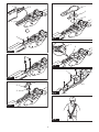
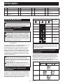
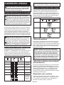
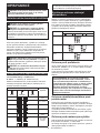
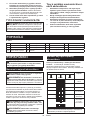
PARTS DESCRIPTION
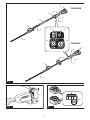
►Fig.1
1Head 2Front grip 3Hanger 4Lever
5Batterycartridge 6Rear grip 7Switch trigger 8Slide sleeve
9Shear blades 10 Speed indicator 11 Power lamp 12 Reverse button
13 Main power button 14 Handle - - - -
FUNCTIONAL DESCRIPTION
CAUTION: Always be sure that the tool is
switched o and the battery cartridge is removed
before adjusting or checking function on the tool.
Installing or removing battery
cartridge
CAUTION: Always switch o the tool before
installing or removing of the battery cartridge.
CAUTION: Hold the tool and the battery car-
tridge rmly when installing or removing battery
cartridge.Failuretoholdthetoolandthebattery
cartridgermlymaycausethemtoslipoyourhands
andresultindamagetothetoolandbatterycartridge
andapersonalinjury.
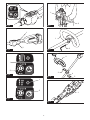
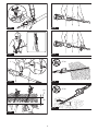
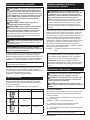
►Fig.2: 1. Red indicator 2. Button 3.Batterycartridge
Toremovethebatterycartridge,slideitfromthetool
while sliding the button on the front of the cartridge.
Toinstallthebatterycartridge,alignthetongueonthe
batterycartridgewiththegrooveinthehousingandslip
itintoplace.Insertitallthewayuntilitlocksinplace
withalittleclick.Ifyoucanseetheredindicatoronthe
uppersideofthebutton,itisnotlockedcompletely.
CAUTION: Always install the battery cartridge
fully until the red indicator cannot be seen. If not,
itmayaccidentallyfalloutofthetool,causinginjuryto
youorsomeonearoundyou.
CAUTION: Do not install the battery cartridge
forcibly.Ifthecartridgedoesnotslideineasily,itis
notbeinginsertedcorrectly.
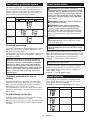
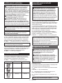
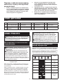
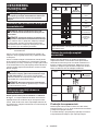
Indicating the remaining battery
capacity
Only for battery cartridges with the indicator
►Fig.3: 1. Indicator lamps 2. Check button
Pressthecheckbuttononthebatterycartridgetoindi-
catetheremainingbatterycapacity.Theindicatorlamps
light up for a few seconds.
Indicator lamps Remaining
capacity
Lighted O Blinking
75% to 100%
50% to 75%
25% to 50%
0% to 25%
Charge the
battery.
Thebattery
mayhave
malfunctioned.
NOTE: Depending on the conditions of use and the
ambienttemperature,theindicationmaydierslightly
fromtheactualcapacity.

14 ENGLISH
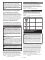
Tool / battery protection system
Thetoolisequippedwithatool/batteryprotectionsys-
tem.Thissystemautomaticallycutsopowertothe
motortoextendtoolandbatterylife.Thetoolwillauto-
maticallystopduringoperationifthetoolorbatteryis
placed under one of the following conditions:
Status Indicator lamps
On O Blinking
Overload
Overheat
Over
discharge
Overload protection
Ifthetoolisoverloadedbyentangledbranchesorother
debris, the indicators for "2" and "3" start blinking and
thetoolautomaticallystops.
Inthissituation,turnthetooloandstoptheapplication
that caused the tool to become overloaded. Then turn
the tool on to restart.
NOTICE: Depending on the usage conditions,
the tool is automatically turned o without any
indication if the tool is overloaded by entangled
branches or debris. In this case, switch o the
tool and remove the battery cartridge, and then
remove entangled branches or debris using tools
such as pliers. After removing the branches or
debris, install the battery cartridge and turn on
the tool again.
Overheat protection for tool or
battery
Therearetwotypesofoverheating;tooloverheating
andbatteryoverheating.Whenthetooloverheating
occurs,allspeedindicatorsblink.Whenthebattery
overheating occurs, indicator for "1" blinks.
Iftheoverheatingoccurs,thetoolstopsautomatically.
Letthetooland/orbatterycooldownbeforeturningthe
tool on again.
Overdischarge protection
Whenthebatterycapacitybecomeslow,thetoolstops
automaticallyandindicatorfor"1"blinks.
If the tool does not operate even when the switches are
operated,removethebatteryfromthetoolandcharge
thebattery.
Power switch action
WARNING: For your safety, this tool is
equipped with lever which prevents the tool from
unintended starting. NEVER use the tool if it runs
when you simply pull the switch trigger without
pressing the lever. Return the tool to our autho-
rized service center for proper repairs BEFORE
further usage.
WARNING: NEVER tape down or defeat pur-
pose and function of lever.
WARNING: Before installing the battery
cartridge on the tool, always check to see that
the switch trigger and lever actuate properly
and return to the "OFF" position when released.
Operating a tool with a switch that does not actuate
properlycanleadtolossofcontrolandseriousper-
sonalinjury.
CAUTION: Never put your nger on the
switch when carrying.Thetoolmaystartuninten-
tionallyandcauseinjury.
NOTICE: Do not pull the switch trigger hard
without pressing the lever. This can cause switch
breakage.
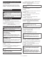
Press the main power button to turn on the tool. The
power lamp lights up when the tool is turned on. To turn
othetool,pressandholdthemainpowerbutton.The
powerlampgoesowhenthetoolisturnedo.
►Fig.4: 1. Power lamp 2. Main power button
NOTE:Thetoolisautomaticallyturnedoifthetoolis
not operated for a certain period.
Topreventtheswitchtriggerfrombeingaccidentally
pulled, a lever is provided. To start the tool, pull the
switch trigger while pressing the lever. Release the
switch trigger to stop.
►Fig.5: 1. Lever 2. Switch trigger
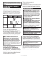
Speed adjusting
Youcanadjustthetoolspeedbypressingthemain
powerbutton.Eachtimeyoupressthemainpower
button, the level of speed changes.
►Fig.6: 1. Speed indicator 2. Main power button
Indicator Mode Stroke speed
High 4,400 min-1
Medium 3,600 min-1
Low 2,000 min-1

15 ENGLISH
Reverse button for debris removal
WARNING: If the entangled branches or
debris cannot be removed by the reverse func-
tion, switch o the tool and remove the bat-
tery cartridge, and then remove the entangled
branches or debris using tools such as pliers.
Failuretoswitchothetoolandremovethebat-
terycartridgemayresultinseriouspersonalinjury
from accidental start-up. Removing the entangled
branchesordebrisbyhandmaycauseaninjury,
sincetheshearbladesmaymoveinreactionto
removing them.
This tool has a reverse button to change the direction
ofshearbladesmovement.Itisonlyforremoving
branches and debris entangled in the tool.
To reverse the shear blades movement, press the reverse
button when the shear blades have stopped, and then pull the
switch trigger while pressing the lever. The power lamp starts
blinking, and the shear blades move in reverse direction.
When entangled branches and debris are removed,
the tool returns to the regular movement and the power
lamp stops blinking and lights up.
►Fig.7: 1. Power lamp 2. Reverse button
NOTE: If the entangled branches or debris cannot be
removed, release the switch trigger, then press the
reverse button, and then pull the switch trigger until
theyareremoved.
NOTE:Ifyoutapthereversebuttonwhiletheshear
blades are still moving, the tool comes to stop and to
bereadyforreversemovement.
Adjusting the cutting angle
CAUTION: Always be sure that the tool is
switched o before folding or unfolding the head.
CAUTION: When folding the head for carrying
the tool or after using the tool, be sure to attach
the blade cover before folding the head.
CAUTION: When folding the head, be careful
not to pinch your ngers between the head and
the slide sleeve.
For DUN500W
Theangleoftheheadcanbeadjustedin6steps.To
change the angle of the head, follow the steps below.
1.
Holdtheheadandtheslidesleeveasshowninthegure.
►Fig.8: 1. Head 2. Slide sleeve
2. Move the head while holding down the slide
sleeve, and then release the slide sleeve.
3. Movetheheadslightlyuntilitislockedwithaclick.
NOTE:Makesurethattheheadissecurelylocked
before operating the tool.
Hex wrench storage
For DUN600L
When not in use, store the hex wrench as illustrated to
keep it from being lost.
►Fig.9: 1. Handle 2. Hex wrench
ASSEMBLY
CAUTION: Always be sure that the tool is
switched o and the battery cartridge is removed
before carrying out any work on the tool.
CAUTION: When replacing the shear blades,
always wear gloves so that your hands do not
directly contact the blades.
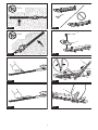
Installing the handle
For DUN600L
1. Attach the upper and lower clamps on the damper.
2. Putthehandleontheupperclampandxitwith
bolts as illustrated.
►Fig.10: 1. Bolt 2. Handle 3. Upper clamp 4. Damper
5. Lower clamp
Installing or removing the shear
blades
CAUTION: Attach the blade cover before
removing or installing the shear blades.
NOTICE: When replacing the shear blades, do
not wipe o grease from the gear and crank.
NOTICE:
For DUN500W
Do not install 600 mm shear blades to your tool.
If600mmshearbladesareinstalledtothetool,you
cannot fold the head of the tool.
NOTE:
For DUN500W
Before installing or removing the shear blades, unfold
the head of the tool so that the head is straight to the
toolbody.
1.
Place the tool upside down, and then remove 6 bolts.
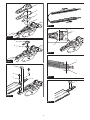
►Fig.11: 1. Bolt
2. Remove the cover, gasket, plate A, and plate B.
►Fig.12: 1. Cover 2. Gasket 3. Plate A 4. Plate B
NOTE:Thegasketorplatesmayremainonthecover.
3. Remove the rod and the bearing.
►Fig.13: 1. Rod 2. Bearing
NOTE:Therodorbearingmayremainonthecover.
4. Remove 2 bolts, 2 sleeves, and the felt pad, and
then remove the shear blades.
►Fig.14: 1. Felt pad 2. Bolt 3. Sleeve 4. Shear blades
NOTICE: Be careful not to lose the bolts.
5. Remove the blade cover, and then attach it to the
new shear blades.
►Fig.15
6. Adjustthecranksothat2holesarelinedupon
the alignment line.
►Fig.16: 1. Hole 2. Alignment line

16 ENGLISH
7. Aligntheprotrusionsontheshearbladesvertically
at the same position.
►Fig.17: 1. Protrusion
8. Attach the felt pad to the shear blades.
►Fig.18: 1. Felt pad
9. Insert the protrusion on the shear blades to the
hole on the rod, then align the position of the felt pad
with the holes on the tool, and then attach the sleeves.
►Fig.19: 1. Felt pad 2. Protrusion 3. Hole 4. Sleeve
NOTICE: Apply a small amount of grease to the
inner periphery of the hole of the rod.
NOTICE: Be careful not to lose the sleeves.
10. Align the holes on the sleeves and the shear
blades with the holes on the tool, and then tighten 2
boltstoxtheshearblades.
►Fig.20: 1. Bolt 2. Hole
11. Attach the bearing and the rod.
►Fig.21: 1. Rod 2. Small hole 3. Bearing
NOTICE: Apply a small amount of grease to the
inner periphery of the small hole of the rod.
NOTICE: Make sure that the protrusion on the
shear blades ts in the small hole on the rod.
12. Attach plate B, plate A, and the gasket.
►Fig.22: 1. Gasket 2. Plate A 3. Plate B
13. Align the hole in the plate with the protrusion on
theshearbladessothattheprotrusiontsinthehole.
►Fig.23: 1. Protrusion 2. Plate
14. Attach the cover, and then tighten 6 bolts.
►Fig.24: 1. Cover 2. Bolt
NOTICE: If the shear blades do not move
smoothly, the shear blades are not engaged with
the rods properly. Install the shear blades again.
NOTICE: If the parts other than the shear
blades such as the rods are worn out, ask Makita
Authorized Service Centers for parts replacement
or repairs.
OPERATION
Attaching the shoulder harness
Optional accessory for DUN500W
CAUTION: Before operation, make sure that
the shoulder harness is properly attached to the
hanger on the tool.
NOTE: Use the shoulder harness attached to the tool.
Beforeoperation,adjusttheshoulderharnessaccord-
ing to the user size to prevent fatigue.
1. Weartheshoulderharnessonyourshoulder.
►Fig.25
2.
Clasp the hook on the shoulder harness to the tool's hanger.
►Fig.26: 1. Hook 2. Hanger
3. Adjusttheshoulderharnesstoacomfortable
working position.
►Fig.27
Theshoulderharnessfeaturesameansofquick
release.
Simplysqueezethesidesofthebuckletoreleasethe
tool from the shoulder harness.
►Fig.28: 1. Buckle
Operating the tool
WARNING: Do not use the tool near any
electrical power lines. Contacting with power lines
orusingthetoolnearpowerlinesmaycauseserious
injuryorelectricshockresultingindeath.
WARNING: Keep hands away from shear
blades.
WARNING: Be extremely careful to maintain
control of the tool at all times. Do not allow the
tool to be deected toward you or anyone in the
work vicinity. Failure to keep control of the tool
couldresultinseriousinjurytothebystanderandthe
operator.
CAUTION: Avoid operating the tool in very
hot weather as much as practicable. When operat-
ing the tool, be careful of your physical condition.
CAUTION: Be careful not to accidentally
contact a metal fence or other hard objects while
trimming.Theshearbladesmaybreakandcause
aninjury.
CAUTION: Be careful not to allow the shear
blades to contact the ground.Thetoolmayrecoil
andcauseaninjury.
CAUTION: Overreaching with a hedge trim-
mer, particularly from a ladder, is extremely
dangerous.Donotworkwhilestandingonanything
wobblyorinrm.
NOTICE: Do not attempt to cut branches thicker
than 10 mm in diameter with the tool. Cut branches
to 10 cm lower than the cutting height using branch
cutters before using the tool.
►Fig.29: (1) Cutting height (2) 10 cm
NOTICE: Do not cut down dead trees or similar
hard objects.Doingsomaydamagethetool.
NOTICE: Do not trim the grass or weeds while
using the shear blades.Theshearbladesmay
become tangled in the grass or weeds.
Hold the tool with both hands.
For DUN500W
►Fig.30
For DUN600L
►Fig.31
Pull the switch trigger while pressing the lever, and then
move the tool forward.
►Fig.32

17 ENGLISH
For basic operation, tilt the shear blades toward the
trimmingdirectionandmoveitcalmlyandslowlyatthe
speed rate of 3 to 4 seconds per meter.
►Fig.33
Tocutahedgesideevenly,cutfromthebottomtotop.
►Fig.34
When trimming to make a round shape (trimming box-
wood or rhododendron, etc.), trim from the root to the
topforabeautifulnish.
►Fig.35
MAINTENANCE
CAUTION: Always be sure that the tool is
switched o and the battery cartridge is removed
before attempting to perform inspection or
maintenance.
CAUTION: When inspecting or maintaining
the tool, always put the tool down. Assembling or
adjustingthetoolinanuprightpositionmayresultin
seriousinjury.
To maintain product SAFETY and RELIABILITY,
repairs,anyothermaintenanceoradjustmentshould
beperformedbyMakitaAuthorizedorFactoryService
Centers,alwaysusingMakitareplacementparts.
Cleaning the tool
Cleanthetoolbywipingodustwithadryclothorone
dippedinsoapywaterandwrungout.
NOTICE: Never use gasoline, benzine, thinner,
alcohol or the like. Discoloration, deformation or
cracks may result.
Shear blade maintenance
Before the operation or once per hour during operation,
applylow-viscosityoil(machineoil,orspray-typelubri-
cating oil) to the shear blades.
►Fig.36
After operation, remove dust from both sides of the
shearbladeswithawiredbrush,wipeitowithacloth
andthenapplylow-viscosityoil(machineoil,orspray-
typelubricatingoil)totheshearblades.
►Fig.37
NOTICE: Do not wash the shear blades in water.
Doingsomaycauserustordamagetothetool.
NOTICE: Dirt and corrosion cause excessive
blade friction and shorten the operating time per
battery charge.
Storage
Attach the blade cover to the shear blades so that the
blades are not exposed. Store the tool out of the reach
of children. Store the tool in a place not exposed to
moisture or rain.
Grinding the shear blades
NOTICE: If the shear blades have considerably
deformed by grinding, replace the shear blades
with new ones.
1. Installthebatterycartridgetothetool.
2. Turn on and start the tool so that the upper blade
andlowerbladearepositionedalternately.
►Fig.38
3. Turnothetoolandremovethebatterycartridge
from the tool.
4. Remove the screw, and then remove the branch
catcher.
►Fig.39: 1. Screw 2. Branch catcher
5. Settheangleofaleto45°,andgrindtheupper
bladefrom3directionswiththele.
►Fig.40: (1) File (2) 45°
CAUTION: Before grinding the shear blades,
make sure that the tool is switched o and the
battery cartridge is removed from the tool.
6. Place the tool upside down, and then remove the
burrsfromtheshearbladeswiththele.
►Fig.41: 1. File
7. Settheangleoftheleto45°,andgrindthelower
bladefrom3directionswiththele.
8. Return the tool to normal position, and then
removetheburrsfromtheshearbladeswiththele.
9. Attachthebranchcatcherbytighteningthescrew.
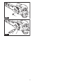
Grease lubrication
Interval of lubrication:Every25operatinghours
1. Remove the bolt from the hole for lubrication.
►Fig.42: 1. Bolt
2. Remove the cap from the grease vessel. Align the
outlet of the grease vessel with the hole on the cover,
and then press the outlet of the grease vessel onto the
hole.
►Fig.43: 1. Grease vessel 2. Hole
3. Applythegreasetothetool(Approximately5gas
a guide).
4. Tighten the bolt.

18 ENGLISH
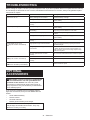
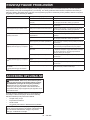
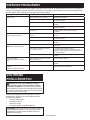
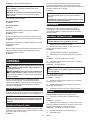
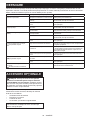
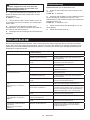
TROUBLESHOOTING
Beforeaskingforrepairs,conductyourowninspectionrst.Ifyoundaproblemthatisnotexplainedinthemanual,
donotattempttodismantlethetool.Instead,askMakitaAuthorizedServiceCenters,alwaysusingMakitareplace-
ment parts for repairs.
State of abnormality Probable cause (malfunction) Remedy
Motor does not run. Batterycartridgeisnotinstalled. Installthebatterycartridge.
Batteryproblem(undervoltage) Rechargethebattery.Ifrechargingisnoteective,
replacebattery.
Thedrivesystemdoesnotwork
correctly.
Askyourlocalauthorizedservicecenterforrepair.
Motor stops running after a little use. Battery'schargelevelislow. Rechargethebattery.Ifrechargingisnoteective,
replacebattery.
Overheating. Stop using of tool to allow it to cool down.
Tool does not reach maximum RPM. Batteryisinstalledimproperly. Installthebatterycartridgeasdescribedinthis
manual.
Batterypowerisdropping. Rechargethebattery.Ifrechargingisnoteective,
replacebattery.
Thedrivesystemdoesnotwork
correctly.
Askyourlocalauthorizedservicecenterforrepair.
Shear blades do not move:
stopthemachineimmediately!
Inappropriate angle of shear blades. Makesurethattheheadisproperlyxedinthe
operational angle.
Foreignobjectsarecaughtbetweenthe
shear blades.
1. Use the reverse button.
2.Switchothetoolandremovethebatterycar-
tridge,andthenremovetheforeignobjectsusing
tools such as pliers.
Thedrivesystemdoesnotwork
correctly.
Askyourlocalauthorizedservicecenterforrepair.
Abnormal vibration:
stopthemachineimmediately!
Shear blades are broken, bent or worn. Replace the shear blades.
Thedrivesystemdoesnotwork
correctly.
Askyourlocalauthorizedservicecenterforrepair.
Shear blades and motor cannot stop:
Removethebatteryimmediately!
Electric malfunction. Removethebatteryandaskyourlocalauthorized
service center for repair.
OPTIONAL
ACCESSORIES
CAUTION: These accessories or attachments
are recommended for use with your Makita tool
specied in this manual.Theuseofanyother
accessories or attachments might present a risk of
injurytopersons.Onlyuseaccessoryorattachment
for its stated purpose.
Ifyouneedanyassistanceformoredetailsregard-
ingtheseaccessories,askyourlocalMakitaService
Center.
• Shearbladeassembly
• Grease vessel
• Shoulder harness
• Makitagenuinebatteryandcharger
NOTE:Someitemsinthelistmaybeincludedinthe
toolpackageasstandardaccessories.Theymay
dierfromcountrytocountry.

19 POLSKI
POLSKI (Instrukcja oryginalna)
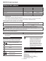
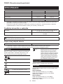
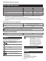
DANE TECHNICZNE
Model: DUN500W DUN600L
Długośćostrza 500 mm 600 mm
Liczbaoscylacjinaminutę 2 000 / 3 600 / 4 400 min-1
Kątostrzatnącego 115°(wgórę45°,wdół70°) –
Długośćcałkowita 2 115 mm 2 050 mm
Napięcieznamionowe Prądstały18V
Masa netto 3,9–4,3 kg 3,7–4,1 kg
• Wzwiązkuzestaleprowadzonymprzeznasząrmęprogramembadawczo-rozwojowymniniejszedanemogą
uleczmianombezwcześniejszegopowiadomienia.
• Danetechnicznemogąróżnićsięwzależnościodkraju.
• Masamożebyćróżnawzależnościodosprzętu,wtymakumulatora.Wtabeliprzedstawionajestnajlżejszai
najcięższakonguracja,zgodniezprocedurąEPTA01/2014.
Kompatybilne akumulatory i ładowarki
Akumulator BL1815N / BL1820 / BL1820B / BL1830 / BL1830B / BL1840 /
BL1840B / BL1850 / BL1850B / BL1860B
Ładowarka DC18RC / DC18RD / DC18RE / DC18SD / DC18SE / DC18SF /
DC18SH
•
Pewnezwymienionychpowyżejakumulatorówiładowarekmogąbyćniedostępnewregioniezamieszkaniaużytkownika.
OSTRZEŻENIE: Należy używać wyłącznie akumulatorów i ładowarek wymienionych powyżej.
Używanieinnychakumulatorówiładowarekmożestwarzaćryzykowystąpieniaobrażeńciałalubpożaru.
Zalecany adapter akumulatora
Adapter akumulatora PDC01
• Adapteryakumulatorówwymienionepowyżejmogąbyćniedostępnewregioniezamieszkaniaużytkownika.
• Przedużyciemadapteraakumulatoranależyprzeczytaćinstrukcjęorazostrzeżeniaumieszczonenaadapterze
akumulatora.
Symbole
Poniżejpokazanosymbolezastosowanenaurządze-
niu.Przedrozpoczęciemużytkowanianależyzapoznać
sięzichznaczeniem.
Przeczytaćinstrukcjęobsługi.
Chronićprzedwilgocią.
Nosićkask,gogleorazochronnikisłuchu.
Ryzykozakleszczenia.
Uważaćnaprzewodyelektryczne,ryzyko
porażeniaprądem.
Zachowaćodległośćconajmniej15m.
Ni-MH
Li-ion
DotyczytylkopaństwUE
Niewyrzucaćurządzeńelektrycznychani
akumulatorów wraz z odpadami z gospo-
darstwa domowego!
Zgodniezdyrektywamieuropejskimiw
sprawiezużytegosprzętuelektrycznegoi
elektronicznego oraz baterii i akumulato-
róworazzużytychbateriiiakumulatorów,
atakżedostosowaniemichdoprawa
krajowego,zużyteurządzeniaelektryczne,
baterieiakumulatory,należyskładować
osobnoiprzekazywaćdozakładurecy-
klingudziałającegozgodniezprzepisami
dotyczącymiochronyśrodowiska.
Przeznaczenie
Narzędzietojestprzeznaczonedoprzycinaniażywopłotów.
Hałas
TypowyrównoważnypoziomdźwiękuAokreślonyw
oparciuonormęEN62841-4-2:
Model DUN500W
Poziomciśnieniaakustycznego(LpA): 81,5 dB(A)
Poziommocyakustycznej(LWA): 92,5 dB (A)
Niepewność(K):3dB(A)

20 POLSKI
Model DUN600L
Poziomciśnieniaakustycznego(LpA): 82,5 dB(A)
Poziommocyakustycznej(LWA): 93,5 dB (A)
Niepewność(K):3dB(A)
WSKAZÓWKA:Deklarowanawartośćemisjihałasu
zostałazmierzonazgodniezestandardowąmetodą
testowąimożnająwykorzystaćdoporównywania
narzędzi.
WSKAZÓWKA:Deklarowanąwartośćemisjihałasu
możnatakżewykorzystaćwewstępnejocenie
narażenia.
OSTRZEŻENIE: Nosić ochronniki słuchu.
OSTRZEŻENIE:
Poziom hałasu wytwarzanego
podczas rzeczywistego użytkowania elektronarzę-
dzia może się różnić od wartości deklarowanej w
zależności od sposobu użytkowania narzędzia, a w
szczególności od rodzaju obrabianego elementu.
OSTRZEŻENIE:
W oparciu o szacowane narażenie
w rzeczywistych warunkach użytkowania należy określić
środki bezpieczeństwa w celu zapewnienia ochrony ope-
ratora (uwzględniając wszystkie elementy cyklu działania,
tj. czas, kiedy narzędzie jest wyłączone i kiedy pracuje na
biegu jałowym, a także czas, kiedy jest włączone).
Drgania
Obowiązującanorma:EN62841-4-2
Model
Lewaręka(przedniarękojeść/uchwyt)
Prawaręka(rękojeśćtylna)
ah (m/s2)NiepewnośćK
(m/s2)
ah (m/s2)NiepewnośćK
(m/s2)
DUN500W 4,7 1,5
2,5 m/s2lubmniej
1,5
DUN600L 3,8 1,5 2,7 1,5
WSKAZÓWKA:Deklarowanawartośćpoziomudrgańzostałazmierzonazgodniezestandardowąmetodą
testowąimożnająwykorzystaćdoporównywanianarzędzi.
WSKAZÓWKA:Deklarowanąwartośćpoziomudrgańmożnatakżewykorzystaćwewstępnejocenienarażenia.
OSTRZEŻENIE: Drgania wytwarzane podczas rzeczywistego użytkowania elektronarzędzia mogą się
różnić od wartości deklarowanej w zależności od sposobu użytkowania narzędzia, a w szczególności od
rodzaju obrabianego elementu.
OSTRZEŻENIE: W oparciu o szacowane narażenie w rzeczywistych warunkach użytkowania należy
określić środki bezpieczeństwa w celu zapewnienia ochrony operatora (uwzględniając wszystkie elementy
cyklu działania, tj. czas, kiedy narzędzie jest wyłączone i kiedy pracuje na biegu jałowym, a także czas,
kiedy jest włączone).
Deklaracja zgodności WE
Dotyczy tylko krajów europejskich
DeklaracjazgodnościWEjestdołączonajakozałącznik
Adoniniejszejinstrukcjiobsługi.
OSTRZEŻENIA
DOTYCZĄCE
BEZPIECZEŃSTWA
Ogólne zasady bezpiecznej
eksploatacji elektronarzędzi
OSTRZEŻENIE: Należy zapoznać się z
ostrzeżeniami dotyczącymi bezpieczeństwa,
instrukcjami, ilustracjami i danymi technicz-
nymi dołączonymi do tego elektronarzędzia.
Niezastosowaniesiędopodanychponiżejinstrukcji
możeprowadzićdoporażeniaprądem,pożarui/lub
poważnychobrażeńciała.
Wszystkie ostrzeżenia i instruk-
cje należy zachować do wykorzy-
stania w przyszłości.
Pojęcie„elektronarzędzie",występującewwymienio-
nychtuostrzeżeniach,odnosisiędoelektronarzędzia
zasilanegozsiecielektrycznej(zprzewodemzasilają-
cym)lubdoelektronarzędziaakumulatorowego(bez
przewoduzasilającego).
Ostrzeżenia dotyczące
bezpieczeństwa dla akumulatorowych
nożyc do żywopłotu na wysięgniku
1.
Nie wolno zbliżać żadnych części ciała do ostrza.
Ciętego materiału nie wolno usuwać ani przytrzy-
mywać, kiedy ostrza są w ruchu.Ostrzaporuszająsię
nawetpowyłączeniunarzędziazapomocąprzełącz-
nika.Momentnieuwagipodczaspracyznożycamido
żywopłotumożespowodowaćpoważneobrażeniaciała.
2. Nożyce do żywopłotu przenosić za pomocą
uchwytu po zatrzymaniu ostrza, zachowując
ostrożność, aby nie nacisnąć żadnego prze-
łącznika zasilania.Prawidłoweprzenoszenie
nożycdożywopłotuzmniejszyryzykoprzypadko-
wegouruchomieniaiobrażeńciałaspowodowa-
nychprzezostrza.
Pagina se încarcă...
Pagina se încarcă...
Pagina se încarcă...
Pagina se încarcă...
Pagina se încarcă...
Pagina se încarcă...
Pagina se încarcă...
Pagina se încarcă...
Pagina se încarcă...
Pagina se încarcă...
Pagina se încarcă...
Pagina se încarcă...
Pagina se încarcă...
Pagina se încarcă...
Pagina se încarcă...
Pagina se încarcă...
Pagina se încarcă...
Pagina se încarcă...
Pagina se încarcă...
Pagina se încarcă...
Pagina se încarcă...
Pagina se încarcă...
Pagina se încarcă...
Pagina se încarcă...
Pagina se încarcă...
Pagina se încarcă...
Pagina se încarcă...
Pagina se încarcă...
Pagina se încarcă...
Pagina se încarcă...
Pagina se încarcă...
Pagina se încarcă...
Pagina se încarcă...
Pagina se încarcă...
Pagina se încarcă...
Pagina se încarcă...
Pagina se încarcă...
Pagina se încarcă...
Pagina se încarcă...
Pagina se încarcă...
Pagina se încarcă...
Pagina se încarcă...
Pagina se încarcă...
Pagina se încarcă...
Pagina se încarcă...
Pagina se încarcă...
Pagina se încarcă...
Pagina se încarcă...
Pagina se încarcă...
Pagina se încarcă...
Pagina se încarcă...
Pagina se încarcă...
Pagina se încarcă...
Pagina se încarcă...
Pagina se încarcă...
Pagina se încarcă...
Pagina se încarcă...
Pagina se încarcă...
Pagina se încarcă...
Pagina se încarcă...
Pagina se încarcă...
Pagina se încarcă...
Pagina se încarcă...
Pagina se încarcă...
Pagina se încarcă...
Pagina se încarcă...
Pagina se încarcă...
Pagina se încarcă...
Pagina se încarcă...
Pagina se încarcă...
Pagina se încarcă...
Pagina se încarcă...
Pagina se încarcă...
Pagina se încarcă...
Pagina se încarcă...
Pagina se încarcă...
-
 1
1
-
 2
2
-
 3
3
-
 4
4
-
 5
5
-
 6
6
-
 7
7
-
 8
8
-
 9
9
-
 10
10
-
 11
11
-
 12
12
-
 13
13
-
 14
14
-
 15
15
-
 16
16
-
 17
17
-
 18
18
-
 19
19
-
 20
20
-
 21
21
-
 22
22
-
 23
23
-
 24
24
-
 25
25
-
 26
26
-
 27
27
-
 28
28
-
 29
29
-
 30
30
-
 31
31
-
 32
32
-
 33
33
-
 34
34
-
 35
35
-
 36
36
-
 37
37
-
 38
38
-
 39
39
-
 40
40
-
 41
41
-
 42
42
-
 43
43
-
 44
44
-
 45
45
-
 46
46
-
 47
47
-
 48
48
-
 49
49
-
 50
50
-
 51
51
-
 52
52
-
 53
53
-
 54
54
-
 55
55
-
 56
56
-
 57
57
-
 58
58
-
 59
59
-
 60
60
-
 61
61
-
 62
62
-
 63
63
-
 64
64
-
 65
65
-
 66
66
-
 67
67
-
 68
68
-
 69
69
-
 70
70
-
 71
71
-
 72
72
-
 73
73
-
 74
74
-
 75
75
-
 76
76
-
 77
77
-
 78
78
-
 79
79
-
 80
80
-
 81
81
-
 82
82
-
 83
83
-
 84
84
-
 85
85
-
 86
86
-
 87
87
-
 88
88
-
 89
89
-
 90
90
-
 91
91
-
 92
92
-
 93
93
-
 94
94
-
 95
95
-
 96
96


Makita DUN600L Manual de utilizare
- Categorie
- Aparate de tuns gard viu
- Tip
- Manual de utilizare
în alte limbi
- slovenčina: Makita DUN600L Používateľská príručka
- polski: Makita DUN600L Instrukcja obsługi
Lucrări înrudite
-
Makita DUH506 Manual de utilizare
-
Makita DUH601Z Manual de utilizare
-
Makita DUH502 Manual de utilizare
-
Makita DUH604S Manual de utilizare
-
Makita UH014 Manual de utilizare
-
Makita DUN461W Manual de utilizare
-
Makita DUM166 Manual de utilizare
-
Makita UH004G Manual de utilizare
-
Makita UH013G Manual de utilizare
-
Makita DUH481 Manual de utilizare