
Enterprise 10G Gateway
Router with DPI
Model: USG-XG-8

Introduction
Thank you for purchasing the Ubiquiti Networks® UniFi®
Security Gateway XG. This Quick Start Guide is designed
to guide you through installation and also includes
warrantyterms.
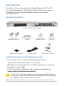
Package Contents
UniFi Security Gateway XG
Mounting
Brackets (Qty. 2)
Bracket Screws
(Qty. 8)
Mounting
Screws (Qty. 4)
Cage Nuts
(Qty. 4)
Enterprise 10G Gateway
Router with DPI
Model: USG-XG-8
Rubber Feet (Qty. 4) Power Cord Quick Start Guide
UniFi Controller System Requirements
• Linux, MacOSX, or Microsoft Windows 7/8/10
• Java Runtime Environment 7 (or above)
• Web Browser: Google Chrome (Other browsers may have
limited functionality)
• UniFi Controller software v5.6 or higher (available at:
www.ubnt.com/download/unifi)
IMPORTANT: We strongly recommend using UPS backup
and power regulation to prevent equipment damage due
to stability issues with local AC power.
TERMS OF USE: All Ethernet cabling runs must use CAT5 (or above). It is the professional
installer’s responsibility to follow local country regulations and indoor cabling requirements.

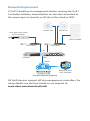
Network Requirement
A UniFi Cloud Key or management station running the UniFi
Controller software, located either on-site and connected to
the same Layer-2 network, or off-site in the cloud or NOC
Remote Access to
UniFi Controller
UniFi Switch
USG-XG-8
Internet
UAP-AC-PRO UAP-AC-HD
LAN
WAN
UniFi Application Server
(UniFi Controller)
UniFi Switch
UAP-AC-M-PRO
1G 1G
DOWNLOAD THROUGHPUT & LATENCY
DEVICES ON 2.4 GHZ CHANNEL
DEVICES ON 5 GHZ CHANNEL
UPLOAD THROUGHPUT & LATENCY
LATENCY THROUGHPUT
SPEED TEST
msec Mbps
7 0.94 1
2.33
25 22
597
0.9 116
200+0 700+0
0.01 413
2290.2
2 118
547
ACTIVE DEVICE
WAN
Inacve 0
Pending
0
Inacve 0
Pending
0
7
ACTIVE DEVICES
Inacve 0
Pending
0
118
ACTIVE DEVICES
LAN WLAN
DEEP PACKET INSPECTIONCLIENTSDEVICES
250
200
150
100
50
0
10
8
6
4
2
0
24 HRS 12 HRS NOW
Avg/Max Throughput Latency
Latency [msec]
Throughput [Mbps]
100
80
60
40
20
0
10
8
6
4
2
0
24 HRS 12 HRS NOW
Latency [msec]
Throughput [Mbps]
Network Protocols
Streaming Media
Web / Web 2.0
File Transfer
Social Network
Other
Motorola
Lenovo
SamsungE
Dell
Acer
Other
WLAN
LAN
WAN
118
7
1
582 GB
23.3 GB
22.7 GB
8.47 GB
3.6 GB
5.46 GB
258
241
220
213
130
110
126
DEVICES
645 GB
TRAFFIC
1172
CLIENTS
1 2 3 4 5 6 7 8 9 10 11
36 40 44 48 52 56 60 64
100 104 108 112 116 120 124 128
132 136 140 144 149 153 157 161 165
CURRENT SITE
Default
USERNAME
admin
Sample Network Diagram
All UniFi devices support off-site management controllers. For
setup details, see the User Guide on our website at:
www.ubnt.com/download/unifi

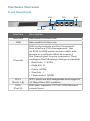
Hardware Overview
Front Panel Ports
Console
SFP+
USB
microSD
RJ45
Interface Description
microSD Reserved for future use.
USB Reserved for future use.
Console
RJ45 serial console port for Command
Line Interface (CLI) management. Use
an RJ45-to-DB9 serial console cable, also
known as a rollover cable, to connect
the Console port to your computer. Then
configure the following settings as needed:
• Baud rate 115200
• Data bits 8
• Parity NONE
• Stop bits 1
• Flow control NONE
SFP+
(Ports 1-8)
SFP+ ports are hot-swappable and support
10 Gbps fiber SFP modules.
RJ45
(Port 0)
RJ45 port supports 10/100/1000 Ethernet
connections.

Front Panel System LED
System
State Status
White Factory defaults, waiting for integration.
Blue
Successfully integrated into a network
and working properly.
Flashing White Bootup in progress.
Flashing Blue Firmware upgrade is taking place.
Front Panel LCD Display
1G
10G
1
378.9
Mbps
535.1
Mbps
2
378.9
Mbps
682.1
Mbps
3
35.7
Mbps
222.9
Mbps
7
1.6
Gbps
5.9
Gbps
8
2.2
Gbps
3.8
Gbps
0
829.3
Mbps
934.9
Mbps
5
/
6
/
# 1
WAN1
192.168.1.1
192.168.122.22
192.168.12.32
32d 1h 52m 5s
CLIENTS
726
192.168.99.233
USG-XG
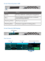
LCD Display
Port Screen
1G
10G
1
378.9
Mbps
535.1
Mbps
2
378.9
Mbps
682.1
Mbps
3
35.7
Mbps
222.9
Mbps
7
1.6
Gbps
5.9 Gbps
8
2.2
Gbps
3.8
Gbps
0
829.3
Mbps
934.9
Mbps
5
/
6
/
# 1 WAN1
192.168.1.1
192.168.122.22
192.168.12.32
32d 1h 52m 5s
CLIENTS
726
192.168.99.233
USG-XG
System and InterfacesPorts 1-4 Ports 5-8
Port 0

Section of
LCD
Information Displayed
Ports 1-4,
Ports 5-8
Information on each SFP+ port:
• Port Speed 1G or 10G
Note: There are two groups of ports:
ports 1-4 and ports 5-8. All ports in
each group operate at the same speed.
For example, if port 1 is set to 1G, then
ports 2-4 will also operate at 1G.
• Port Number 1 to 8
• Interface Type - Primary WAN;
- Other WAN; No icon - LAN port
• Throughput Upload (blue) and download
(green) throughput speeds
• / Port is disconnected
• X Port is disabled
A white outline indicates the currently
selected port.
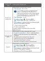
System and
SFP+
Information on the selected SFP+ port:
• # <port><interface> Port: 1 to 8; Interface:
WAN or LAN followed by the WAN/LAN
number
• IP address(es) assigned to the port
• Uptime if port is up; or Disabled or
Disconnected if port is down
• Number of clients (active connections)
Port 0
Information on RJ45 port 0:
• Interface Type - Primary WAN;
- Other WAN; No icon - LAN port
• Throughput Upload (blue) and download
(green) throughput speeds
• IP address of the Primary WAN

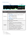
Statistics Screen
THROUGHPUT
5.4
Gbps
12.1
Gbps
BYTES
21.3
GB
284
GB
PACKETS
71.8
1.59
192.168.99.233
USG-XG
34%CPU
34%RAM
TMP.
LATENCY
MS
CLIENTS
743
3
G
M
34
o
c
System Details
Statistics
Section of
LCD
Information Displayed
Statistics
Statistics on uploaded (blue) and downloaded
(green) data:
• Throughput Total throughput speed in
bps/kbps/Mbps/Gbps
• Bytes Total bytes (B)*
• Packets Total packets*
• Bar Graphs Plots of data uploaded and
downloaded
System
Details
Information on the system:
• Host name
• IP address of the primary WAN port
• Latency in ms for the Primary WAN or
selected port
• Number of clients (active connections) for
the Primary WAN or selected port
• CPU and RAM usage percentage (red
indicates usage of 90% or greater)
• Temperature of CPU in °C (red indicates
temperature of 85 °C or greater)
* Units:
k = 2
10
= 1024
M = 2
20
≈ 1,000,000
G = 2
30
≈ 1,000,000,000
T = 2
40
≈ 1,000,000,000,000
P = 2
50
≈ 1,000,000,000,000,000

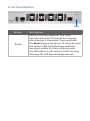
Front Panel Button
Reset
Button Description
Reset
Resets to factory defaults. The UniFi
Security Gateway XG should be running
after bootup is complete. Press and hold
the Reset button for about 10 seconds until
the System LED starts flashing and then
becomes solidly lit. After a few seconds,
the LED will turn off, and the UniFi Security
Gateway XG will automatically reboot.

Back Panel
Fans
AC/DC
PSU Module
PSU 2
Module Bay
The USG-XG-8 includes one hot-swappable AC/DC PSU
module. An optional AC/DC PSU module can be installed in
the PSU 2 Module Bay.
You also have the option to use a DC/DC PowerModule
™
,
model RPS-DC-100W (sold separately).
Note: There are ventilation holes on the sides of the UniFi
Security Gateway XG.

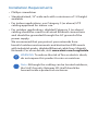
Installation Requirements
• Phillips screwdriver
• Standard-sized, 19" wide rack with a minimum of 1U height
available
• For indoor applications, use Category 5 (or above) UTP
cabling approved for indoor use.
• For outdoor applications, shielded Category 5 (or above)
cabling should be used for all wired Ethernet connections
and should be grounded through the AC ground of the
power supply.
We recommend that you protect your networks from
harmful outdoor environments and destructive ESD events
with industrial-grade, shielded Ethernet cable from Ubiquiti
Networks. For more details, visit: www.ubnt.com/toughcable
WARNING: To reduce the risk of fire or electric shock,
do not expose this product to rain or moisture.
Note: Although the cabling can be located outdoors,
the UniFi Security Gateway XG itself should be
housed inside a protective enclosure.

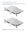
Hardware Installation
The UniFi Security Gateway XG can be placed on a horizontal
surface, mounted on a wall, or mounted on a rack.
WARNING: FAILURE TO PROVIDE PROPER VENTILATION
MAY CAUSE FIRE HAZARD. KEEP AT LEAST 20 MM OF
CLEARANCE NEXT TO THE VENTILATION HOLES FOR
ADEQUATE AIRFLOW.
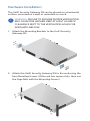
1. Attach the Mounting Brackets to the UniFi Security
GatewayXG.
2. Attach the UniFi Security Gateway XG to the rack using the
four Mounting Screws. (If the rack has square slots, then use
the Cage Nuts with the Mounting Screws.)

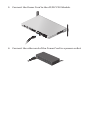
3. Connect the Power Cord to the AC/DC PSU Module.
4. Connect the other end of the Power Cord to a power outlet.

Connecting Ethernet to LAN
Connect a U Fiber 10Gbps SFP+ optical module and fiber optic
patch cable to SFP+ port 1.
For detailed instructions on using SFP+ ports, refer to Using
SFP+ Ports.

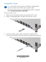
Using SFP+ Ports
Note: Each SFP+ port requires a U Fiber 10 Gbps SFP+
optical module and a fiber optic patch cable.
For information about compatible fiber SFP+ modules,
visit: community.ubnt.com/unifi
To use an SFP+ port:
1. Remove the protective plug covering the SFP+ port.
2. Plug a compatible fiber module into the SFP+ port.
3. Connect a fiber optic cable to the fiber module. Then
connect the other end of the cable to another fiber device.
*640-00305-03*
640-00305-03

Initial Setup via Bluetooth
Use the UniFi Mobile app to configure the UniFi Security
Gateway XG.
1. Download the UniFi Mobile app from the AppStore (iOS)
or Google Play
™
(Android).
2. Enable Bluetooth on your mobile device.
3. Launch the app and hold your mobile device within 1.5m
(5') of the UniFi Security Gateway XG.
4. Follow the on-screen instructions to set up the UniFi
Security Gateway XG.
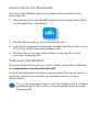
Software Installation
Download the latest version of the UniFi Controller software
at: www.ubnt.com/download/unifi
From a management station connected to the same Layer-2
network, launch the installer and follow the on-screen
instructions.
Note: If you already have UniFi Controller v5.6 or higher
installed, go to the section, Adopting the UniFi Security
Gateway XG.

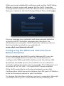
After you have installed the software and run the UniFi Setup
Wizard, a login screen will appear for the UniFi Controller
management interface. Enter the Admin Name and Password
that you created in the UniFi Setup Wizard. Then click Login.
You can manage your network and view network statistics
using the UniFi Controller management interface. For
information on using the UniFi Controller software, refer to
the User Guide located on our website at:
www.ubnt.com/download/unifi
Configuring the WAN and LAN Interfaces
Before Adoption
Prior to adopting the UniFi Security Gateway XG, you can
access its Configuration Interface via a web browser to
configure the WAN and LAN interfaces and the inform URL.
By default, the WAN port is set to DHCP so it can obtain its
network settings from the service provider. The LAN port is set
to a static IP of 192.168.1.1/24 with DHCP Server enabled.
If the UniFi controller is on the local network, access the
Configuration Interface and configure the LAN port’s IP Address
to be on the same subnet as your controller.
To change the interface settings, connect a computer (through
a switch) to SFP+ port 1 of the UniFi Security Gateway XG.

1. From a web browser, go to: https://setup.ubnt.com
https://setup.ubnt.com
2. The UniFi Security Gateway XG Settings window will appear.
Click Configuration to continue.
3. In the Configuration window, configure the WAN Settings,
LAN Settings, and Inform URL as needed.
4. Click Apply Changes to save the changes.

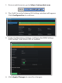
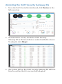
Adopting the UniFi Security Gateway XG
1. From the UniFi Controller dashboard, click Devices in the
left menu bar.
2. On the Devices screen, locate the UniFi Security
GatewayXG in the list of devices under the Model column.
To adopt it, click Adopt.
3. The System LED on the UniFi Security Gateway XG will turn
blue to confirm that it is successfully adopted.

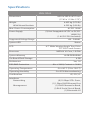
Specifications
USG- XG-8
Dimensions 442.4 x 285.6 x 43.7 mm
(17.42 x 11.24 x 1.72")
Weight
With Mount Brackets
4.435 kg (9.78 lb)
4.535 kg (9.98 lb)
Max. Power Consumption AC/DC 100W
Power Supply (2) Hot-Swappable AC/DC or DC/DC
100W PSU
(1 AC/DC PSU Included)
Supported Voltage Range 100 - 240VAC
System LED Status
LCD 4.7" Wide-Viewing Angle True Color
TFT-LCD Touch Screen
Processor MIPS64 16-Core, 1.8 GHz
System Memory 16 GB DDR4 RAM
On-Board Flash Storage 4 GB
Rackmount Yes, 1U
ESD/EMP Protection Air: ± 24 kV, Contact: ± 24 kV
Operating Temperature -5 to 40° C (23 to 104° F)
Operating Humidity 5 to 95% Noncondensing
Certications CE, FCC, IC
Interfaces
Networking
Management
(8) 10 Gbps SFP+ Ports,
(1) 1 Gbps RJ45 Ethernet Port
(1) RJ45 Ethernet In-Band,
(1) RJ45 Serial Out-of-Band,
(1) Bluetooth 4.0

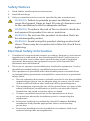
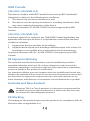
Safety Notices
1. Read, follow, and keep these instructions.
2. Heed all warnings.
3. Only use attachments/accessories specified by the manufacturer.
WARNING: Failure to provide proper ventilation may
cause fire hazard. Keep at least 20 mm of clearance next
to the ventilation holes for adequate airflow.
WARNING: To reduce the risk of fire or electric shock, do
not expose this product to rain or moisture.
WARNING: Do not use this product in location that can
be submerged by water.
WARNING: Avoid using this product during an electrical
storm. There may be a remote risk of electric shock from
lightning.
Electrical Safety Information
1. Compliance is required with respect to voltage, frequency, and current
requirements indicated on the manufacturer’s label. Connection to a
different power source than those specified may result in improper
operation, damage to the equipment or pose a fire hazard if the
limitations are not followed.
2. There are no operator serviceable parts inside this equipment. Service
should be provided only by a qualified service technician.
3. This equipment is provided with a detachable power cord which has
an integral safety ground wire intended for connection to a grounded
safety outlet.
a. Do not substitute the power cord with one that is not the provided
approved type. Never use an adapter plug to connect to a 2-wire
outlet as this will defeat the continuity of the grounding wire.
b. The equipment requires the use of the ground wire as a part of the
safety certification, modification or misuse can provide a shock
hazard that can result in serious injury or death.
c. Contact a qualified electrician or the manufacturer if there
are questions about the installation prior to connecting the
equipment.
d. Protective earthing is provided by Listed AC adapter. Building
installation shall provide appropriate short-circuit backup
protection.
e. Protective bonding must be installed in accordance with local
national wiring rules and regulations.
Pagina se încarcă...
Pagina se încarcă...
Pagina se încarcă...
Pagina se încarcă...
Pagina se încarcă...
Pagina se încarcă...
Pagina se încarcă...
Pagina se încarcă...
-
 1
1
-
 2
2
-
 3
3
-
 4
4
-
 5
5
-
 6
6
-
 7
7
-
 8
8
-
 9
9
-
 10
10
-
 11
11
-
 12
12
-
 13
13
-
 14
14
-
 15
15
-
 16
16
-
 17
17
-
 18
18
-
 19
19
-
 20
20
-
 21
21
-
 22
22
-
 23
23
-
 24
24
-
 25
25
-
 26
26
-
 27
27
-
 28
28


Ubiquiti UniFi Security Gateway XG-8 Ghid de inițiere rapidă
- Tip
- Ghid de inițiere rapidă
- Acest manual este potrivit și pentru
în alte limbi
Lucrări înrudite
-
Ubiquiti UniFi USG Ghid de inițiere rapidă
-
Ubiquiti UniFi USG Ghid de inițiere rapidă
-
-
Ubiquiti US-XG-6POE Ghid de inițiere rapidă
-
Ubiquiti UCKG2-RM Manualul utilizatorului
-
-
-
-
-