Chicago Pneumatic CP86000 Series Manual de utilizare
- Tip
- Manual de utilizare

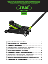
CP86150 / CP86200 / CP86300 / CP86500
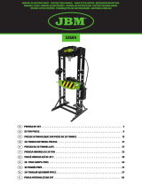
HYDRAULIC PRESS
8940170386 Rev 04 - 09/2022
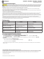
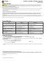
WARNING
To reduce risk of injury, everyone using, installing, repairing, maintaining,
changing accessories on, or working near this tool must read and
understand these instructions, as well as separately provided safety
instructions part number 8940170883, before performing any such task.
Operator’s Manual

Fig. 06
Fig. 05
Fig. 04
Fig. 03
Fig. 02
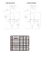
FRAME
TABLE
V-BLOCK
Pin
Feet

CP86150
CP86200
CP86300 & CP86500
Fig. 08
Fig. 07
Fig. 09
Fig. 10
Air Bleed
Valve
Air Valve
Fig. 11
FRAME

1000 1000
1000
1000
CP86150: 135 mm
CP86200: 135 mm
CP86300: 105 mm
CP86500: 130 mm
Fig. 12
Fig. 15
OK NOT OK Fig. 16
Fig. 17
Fig.18
Fig. 14

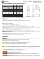
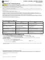
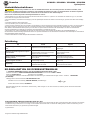
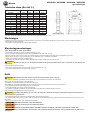
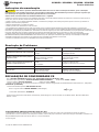
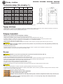
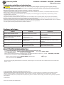
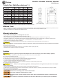
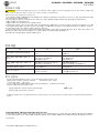
Designation
1
4 Low pressure pump1
5
6
CP86150/CP86200
2Non-return valve
3 High pressure pump1
7 Unloading valve
8 Manometer
9 Oil cylinder
1
1
1
1
1
1
1
1
CP86150
1
1
1
1
1
1
1
1
1
1
1
1
1
1
1
1
1
1
1
CP86500CP86200
CP86300
CP86300/CP86500
Control valve

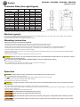
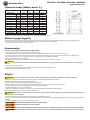
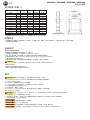
EN English CP86150 / CP86200 / CP86300 / CP86500
Hydraulic press
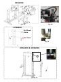
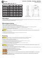
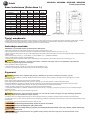
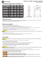
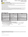
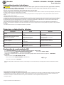
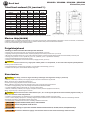
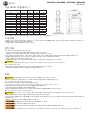
Technical Data (See right figure)
Dimension CP86150 CP86200 CP86300 CP86500
capacity [kg] 15 000 20 000 30 000 50 000
A[mm] 700 740 795 1030
B[mm] 540 700 700 800
C[mm] 882 1772 1772 1830
F[mm] 120 132 140 207
E[mm] 500 510 535 730
F1 [mm] 157 185 151 68
F2 [mm] 457 1175 1031 1048
R[mm] 160 186 160 200
M[mm] / / 200 245
oil [l] 0,6 0,95 1,1 2,5
Weight [kg] 75,5 105 166,7 298
max. pressure [MPa] 61 69 58 62
All values are current as of the date of this publication. For the latest information please visit www.cp.com.
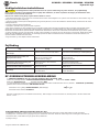
Machine type(s)
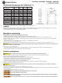
• The machinery described is intended for machinery production and assembling spare parts. It is used to press, size, assemble, rivet small parts in
process No other use permitted. For professional use only.
• Please read the instructions carefully before starting the machine.
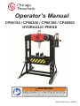
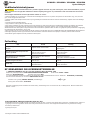
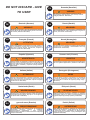
Mounting instruction
Make sure every parts are fixed and tightened.
Document Ref: 8940169914_REV: 01 _ 05-2012
Scale: 1:1
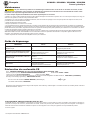
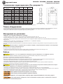
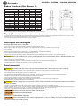
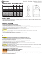
• Attach the base section to the frame (Fig.03) and support to left and right connecting plate. (Fig. 04)
• Assemble the nylon ring to gauge fitting, then put the pressure gauge and twist tight. (Fig. 05/06)
• Remark: twist as tight as possible, otherwise it will be leak. Attach the gauge fitting to the suitable upper cross beam and twist bolt.
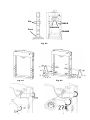
• Assemble pump to the frame and hose kit to the pump Fig. 07 (CP86150), Fig. 09 (CP86200), Fig. 11 (CP86300 & CP86500).
• Insert the complete handle into the opening of the lever support.
• During moving the machine, make sure to use the proper lifting equipment and follow the instructions in document 8940174875 <INSTRUCTIONS
FOR MOVING THE TABLE>
•Main structures of PRESS include Pin, Feet, V-Block, Table, Frame. (Fig. 02)
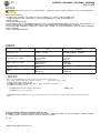
Caution
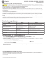
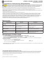
Working area of 1 m must be kept free both in front of and behind the machine while it is in operation so that it
is always easily accessible (Fig.12)
Be careful then use the PESS, SAFETY INSTRUCTIONS in document 8940174875 .(Fig.14)
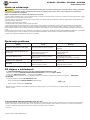
Purge air from the hydraulic system:
• Open the air valve by turning it counterclockwise and purge the air bleed valve (Fig. 09)
• Pump several full stokes to eliminate any air in the system.
Operation
Document Ref: 8940169914_REV: 01 _ 05-2012
Scale: 1:1
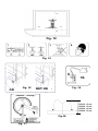
Caution
Ensure table at proper position and lock the table by 4 pins firmly. (Fig.15)
• Close the release valve, by turning it clockwise.
Note :
Press
has an Automatic 2-speed hydraulic pump, equipped with an automatic valve instead of an control valve.
• Pump the handle/foot pedal until serrated saddle nears workpiece.
Align workpiece and ram to ensure center loading.
Document Ref: 8940169914_REV: 01 _ 05-2012
Scale: 1:1
Caution
A single hand-wheel controls the release valve, the switching between fast and slow speed can be done
automatically
• Pump the handle/foot pedal to apply load onto workpiece (see numeration in pressure gauge).
• When work is done, stop pumping, slowly and carefully remove load from workpiece by turning the release valve counterclockwise in small increments.
(must turn with the small angle)
• Once ram has fully retracted, remove workpiece from table.
The V-block must be used by pair, not by piece!
Only one person is allowed to operate the press.
Make sure that the operator must wear protective cloth, gloves, safety helmet, shoes and ear protector
during operating.
To avoid accidents, always be aware of any on-going work on the machine. Also, always stay focused on
the job to be done.

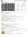
EN English CP86150 / CP86200 / CP86300 / CP86500
Hydraulic press
Maintenance instruction
Do not use damaged/deformed product. If abnormal noise or vibration occurs, stop use immediately, then
inspect and ask manufacturer for help.It is recommended that this inspection be made by a manufacturer’s or supplier’s
authorized repair facility.
The greatest single cause of failure in hydraulic units is dirt.
• Keep the service press clean and well lubricated to prevent foreign matter from entering the system. If the press has been exposed to rain, snow,
sand, or grit, it must be cleaned before it is used.
• Store the press, with pistons completely retracted, in a well-protected area where it will not be exposed to corrosive vapors, abrasive dust, or any
other harmful elements.
• Periodically check the condition of the product.
• Store the product in dry and non-corrosion environment.
• Owners and/or operators should be aware that repair of this equipment may require specialized knowledge and facilities. It is recommended that an
annual inspection of the product be made by a manufacturer’s or supplier’s authorized repair facility and that any defective parts, decals, or safety labels
or signs be replaced with manufacturer’s or supplier’s specified parts. A list of authorized repair facilities is available from the manufacturer or supplier,
please call them for help.
• Any product that appears to be damaged in any way, is found to be worn, or operates abnormally SHALL BE REMOVED FROM SERVICE UNTIL
REPAIRED. It is recommended that necessary repairs be made by a manufacturer’s or supplier’s authorized repair facility if repairs are permitted by the
manufacturer or supplier.
• Only attachments and/or adapters supplied by the manufacturer shall be used.
Trouble Shooting
Fault Cause Remedy
The pump is working, while the ram can't
work 1.The oil pipe loosed the ram is leaking 1.Checking the connecting situation of oil pipes,
replace the oil seals
When open release vavle, the ram can’t
reset
1.The oil pipe loosed
2.No enough space un pump
3.The ram become invalid
1.Checking the connecting situation of oil pipes
2.Open exhaust valve
3.Replace the ram
Manual normal, while ram can’t work 1.Release valve not complete closed
2.air in system
1.check the release valve
2.Purge away the air according manual
The ram can't fully work 1.The oil is not enough 1.Add oil
Oil leaking 1.Seal kits broken
2.Screw parts loosed
1.Replace the seal kits
2.Tighten the screw parts
EC Declaration of conformity
We : CHICAGO PNEUMATIC Tool Co. LLC 1815 Clubhouse Road, SC 29730 - USA
Declare that the product(s): CP86150/CP86200/CP86300/CP86500 Serial Number: 00001 - 99999
Machine type(s): Hydraulic press Origin of the product: China
is in conformity with the requirements of the council Directives on the approximation of the laws of the Member States relating : to “Machinery“
2006/42/EC (17/05/2006)
applicable harmonised standard(s) : EN ISO 16092-1, -3 :2018
Name and position of issuer: PASCAL ROUSSY ( R&D Manager)
Place & Date: Saint-Herblain, 29/08/2022
Document Ref: 8940169914_REV: 01 _ 05-2012
Scale: 1:1
Caution
Technical file available from EU headquarter. Pascal Roussy, R&D manager LLC CP Technocenter 38, rue Bobby Sands - BP10273 44800 Saint
Herblain - France
Copyright 2022, Chicago Pneumatic Tool Co. LLC
All rights reserved. Any unauthorized use or copying of the contents or part thereof is prohibited. This applies in particular to trademarks, model
denominations, part numbers and drawings. Use only authorized parts. Any damage or malfunction caused by the use of unauthorized parts is not
covered by Warranty or Product Liability.
Original Instructions
The design has been validated according to: ASME ASP-2014

DE Deutsch CP86150 / CP86200 / CP86300 / CP86500
Hydraulische Presse
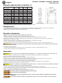
Technische Daten (Siehe Abbildungen 1.)
Abmessungen CP86150 CP86200 CP86300 CP86500
Kapazität [kg] 15 000 20 000 30 000 50 000
A[mm] 700 740 795 1030
B[mm] 540 700 700 800
C[mm] 882 1772 1772 1830
F[mm] 120 132 140 207
E[mm] 500 510 535 730
F1 [mm] 157 185 151 68
F2 [mm] 457 1175 1031 1048
R[mm] 160 186 160 200
M[mm] / / 200 245
oil [l] 0,6 0,95 1,1 2,5
Gewicht [kg] 75,5 105 166,7 298
Max Druck [MPa] 61 69 58 62
Alle Werte aktuell zum Zeitpunkt dieser Veröffentlichung. Gehen Sie für die neuesten Informationen bitte zu www.cp.com.
Typ(en)
• Die beschriebene Maschine ist für die Maschinenproduktion und für die Montage von Ersatzteilen bestimmt. Sie wird zum Pressen, Passen, Montieren
und Nieten von Kleinteilen verwendet Keine andere Verwendung zulässig. Nur für professionelle Verwendung.
• Bitte lesen Sie die Anweisungen sorgfältig durch, bevor Sie die Maschine starten.
Montageanleitung
Prüfen Sie, ob alle Teile befestigt und festgezogen sind.
• Befestigen Sie den Sockel und die Stütze an der linken und rechten Verbindungsplatte. (Abb. 04)
• Setzen Sie den Nylonring auf das Anschlussstück, setzen Sie dann den Druckmesser auf und drehen Sie ihn fest. (Abb. 06)
• Anmerkung: Drehen Sie so fest wie möglich, um Leckagen zu vermeiden. Befestigen Sie das Anschlussstück am passenden oberen Querträger und
drehen Sie die Schraube fest.
• Montieren Sie die Pumpe am Rahmen. Abb. 07 (CP86150), Abb. 09 (CP86200), Abb. 11 (CP86300 & CP86500).
• Führen Sie den kompletten Handgriff in die Öffnung der Hebelstütze ein.
• Benutzen Sie zum Bewegen der Maschine geeignete Hebezeuge und befolgen Sie die abgebildeten Anweisungen (Abb. 02).
Document Ref: 8940169914_REV: 01 _ 05-2012
Scale: 1:1
Caution
Vor und hinter der Maschine muss während des Betriebs ein Arbeitsbereich von jeweils 1 m freigehalten
werden und leicht zugänglich sein.
Entlüften Sie das Hydrauliksystem:
• Öffnen Sie das Ablassventil (Drehen gegen den Uhrzeigersinn) und reinigen Sie das Entlüftungsventil (Abb. 09).
• Pumpen Sie mehrmals mit vollem Hub, um alle Luft aus dem System zu entfernen.
Bedienung
Document Ref: 8940169914_REV: 01 _ 05-2012
Scale: 1:1
Caution
Achten Sie darauf, dass sich der Tisch in der korrekten Position befindet und blockieren Sie ihn durch 4
Stifte. (Abb.15)
• Für CP86150, CP86300 und CP86500, Ablassventil und Regelventil durch Drehen nach rechts schließen.
Hinweis: Die zweistufige Pumpe wird für schnelles Anfahren eingeschaltet.
Für CP86200, Ablassventil durch Drehen nach rechts schließen.
Hinweis: CP86200 verfügt über eine automatische zweistufige Hydraulikpumpe, die mit einem Automatikventil anstatt einem Regelventil ausgestattet ist.
• Drücken Sie mehrmals auf den Griff bzw. das Fußpedal, bis der gezahnte Sattel sich dem Werkstück nähert.
• Richten Sie das Werkstück am Druckkolben aus, um eine mittige Lagerung sicherzustellen.
• Für CP86150, CP86300 und CP86500, Regelventil durch Drehen nach links schließen (langsame Position).
Hinweis: Hinweis: Die zweistufige Pumpe wird für starkes Pressen eingeschaltet.
Document Ref: 8940169914_REV: 01 _ 05-2012
Scale: 1:1
Caution
Vorsicht: Bei Aufbringen der Belastung (15 t, 30 t oder 50 t) muss das Regelwentil geschlossen sein (lang-
same Position), um Schäden an den Systemkomponenten zu verhindern.
• Drücken Sie den Griff bzw. das Fußpedal mehrmals, um einen Druck auf das Werkstück auszuüben (siehe Nummerierung am Manometer).
• Pumpen Sie nach Fertigstellung der Arbeit nicht mehr und senken Sie den Druck auf das Werkstück langsam und vorsichtig, indem Sie das Ablassventil
in kleinen Schritten im Gegenuhrzeigersinn drehen (mit kleinem Winkel drehen).
• Wenn der Druckkolben vollständig eingezogen ist, entfernen Sie das Werkstück vom Tisch.
Der V-Block muss paarweise, nicht einzeln, verwendet werden!
Nur eine Person darf die Presse betreiben.
Stellen Sie sicher, dass der Bediener Schutzkleidung, Handschuhe, Helm, Sicherheitsschuhe und
Ohrschützer während des Betriebs trägt.
Achten Sie zur Unfallvermeidung immer auf laufende Arbeiten an der Maschine. Konzentrieren Sie sich
immer auf die aktuelle Arbeit.

DE Deutsch CP86150 / CP86200 / CP86300 / CP86500
Hydraulische Presse
Wartungsanweisungen
Verwenden Sie keine beschädigten/deformierten Produkte. Falls ungewöhnliche Geräusche oder Vibrationen
auftreten, beenden Sie sofort die Nutzung. Führen Sie dann eine Überprüfung durch und bitten Sie den Hersteller um Hilfe.
Es wird empfohlen, dass diese Überprüfung durch eine vom Hersteller oder Lieferanten autorisierte Reparaturwerkstatt
erfolgt.
Die häufigste einzelne Ursache für Ausfälle in Hydraulikaggregaten ist Schmutz.
• Halten Sie den Hubwagen sauber und gut geschmiert, damit keine Fremdkörper in das System eindringen können. Wenn der Hubwagen Regen,
Schnee, Sand oder Splitt ausgesetzt war, muss er vor der nächsten Verwendung gereinigt werden.
• Lagern Sie den Hubwagen mit vollständig eingefahrenen Kolben in einem gut geschützten Bereich, wo er keinen ätzenden Dämpfe, Schleifstaub oder
anderen schädlichen Elementen ausgesetzt ist.
• Überprüfen Sie in regelmäßigen Abständen den Zustand des Produkts.
• Lagern Sie das Produkt an einem trockenen und nicht korrosiven Umgebung.
• Eigentümer und/oder Bediener sollten sich bewusst sein, dass die Reparatur dieser Geräte möglicherweise spezielles Fachwissen und eine spezielle
Ausrüstung erfordern. Es wird empfohlen, dass eine jährliche Überprüfung des Produkts durch eine vom Hersteller oder Lieferanten autorisierten
Reparaturwerkstatt durchgeführt wird und dass alle defekten Teile, Schilder, Sicherheitsetiketten oder Zeichen durch die vom Hersteller oder Lieferanten
angegebenen Teile ersetzt werden. Eine Liste der autorisierten Reparaturwerkstätten ist beim Hersteller oder Lieferanten erhältlich, rufen Sie sie hierzu
an.
• Jedes Produkt, das in irgendeiner Weise beschädigt oder verschlissen zu sein scheint oder nicht normal funktioniert, DARF NICHT WEITER
VERWENDET WERDEN, BIS ES REPARIERT IST. Es wird empfohlen, dass die notwendigen Reparaturen durch eine vom Hersteller oder Lieferanten
autorisierte Reparaturwerkstatt erfolgt, falls Reparaturen vom Hersteller oder Lieferanten erlaubt werden.
• Nur vom Hersteller geliefertes Zubehör bzw. Adapter dürfen verwendet werden.
Fehlersuche
Fehler Ursache Behebung
Die Pumpe funktioniert, aber der
Druckkolben nicht.
1.Die Ölleitung zum Druckkolben ist locker
und leckt.
1.Kontrolle der Verbindungen der Ölleitungen,
Öldichtungen ersetzen.
Beim Önen des Ablassventils wird der
Druckkolben nicht eingezogen.
1.Die Ölleitung ist locker.
2.Kein ausreichender Platz in Pumpe.
3.Der Druckkolben ist defekt.
1.Kontrolle der Verbindungen der Ölleitungen.
2.Ablassventil önen.
3.Druckkolben ersetzen.
Wenn Gri der Presse betätigt wird,
funktioniert Druckkolben nicht.
1.Überdruckventil nicht vollständig
geschlossen.
2.Luft im System.
1.Überdruckventil kontrollieren.
2.Gemäß Handbuch entlüften.
Der Druckkolben funktioniert nicht korrekt. 1.Keine ausreichende Ölmenge. 1.Öl auüllen.
Ölleck 1.Dichtungen defekt.
2.Schrauben locker.
1.Dichtungen ersetzen.
2.Schrauben festziehen.
EG-KONFORMITÄTSERKLÄRUNG
Wir: CHICAGO PNEUMATIC Tool Co. LLC 1815 Clubhouse Road, SC 29730 - USA
Erklären hiermit, dass das (die) Produkt(e): CP86150/CP86200/CP86300/CP86500 Serial Number: 00001 - 99999
Typ(en): Hydraulische Presse Produktherkunft: China
den Anforderungen der EG-Richtlinie zur Angleichung der Rechtsvorschriften der Mitgliedsstaaten entspricht: für “Maschinen” 2006/42/EC
(17/05/2006)
Geltende harmonisierte Norme(n): EN 693:2001+A1+A2
Name und Position des Ausstellers: PASCAL ROUSSY ( R&D Manager)
Ort und Datum: Saint-Herblain, 12/02/2019
Technische Datei bei EU-Hauptbüro erhältlich. Pascal Roussy, R&D manager LLC CP Technocenter 38, rue Bobby Sands - BP10273 44800 Saint
Herblain - France
Copyright 2019, Chicago Pneumatic Tool Co. LLC
Alle Rechte vorbehalten. Jede nicht ausdrücklich genehmigte Verwendung oder Vervielfältigung des Inhalts, ob ganz oder auszugsweise, ist untersagt.
Dies gilt insbesondere auch für Handelsmarken, Modellbezeichnungen, Teilenummern und Zeichnungen. Nur vom Hersteller zugelassene Ersatzteile
benutzen! Schäden oder Funktionsstörungen, die durch die Verwendung nicht autorisierter Teile verursacht wird, wird von der Garantie oder
Produkthaftung nicht abgedeckt.
Ursprüngliche Betriebsanleitung
Document Ref: 8940169914_REV: 01 _ 05-2012
Scale: 1:1
Caution
Das Design wurde nach validierten: ASME ASP-2014

FR Français CP86150 / CP86200 / CP86300 / CP86500
Presse hydraulique
Données techniques (Voir gure 1.)
Dimensions CP86150 CP86200 CP86300 CP86500
Capacité [kg] 15 000 20 000 30 000 50 000
A[mm] 700 740 795 1030
B[mm] 540 700 700 800
C[mm] 882 1772 1772 1830
F[mm] 120 132 140 207
E[mm] 500 510 535 730
F1 [mm] 157 185 151 68
F2 [mm] 457 1175 1031 1048
R[mm] 160 186 160 200
M[mm] / / 200 245
oil [l] 0,6 0,95 1,1 2,5
Poids [kg] 75,5 105 166,7 298
Pression max. [MPa] 61 69 58 62
Toutes les valeurs sont justes à la date de cette publication. Pour obtenir les dernières informations, veuillez consulter www.cp.com.
Type(s) de machine
• Les machines décrites sont conçues pour la production de machines et l'assemblage de pièces détachées. Elles servent à presser, dimensionner,
assembler et riveter de petites pièces en cours de fabrication. Aucune autre utilisation n'est autorisée. Réservé à un usage professionnel.
• Veuillez lire attentivement les instructions avant de démarrer la machine.
Instruction de montage
S'assurer que toutes les pièces sont fixées et serrées.
• Fixer la section de base et le support à la plaque de raccordement gauche et droite. (Fig. 04)
• Assembler l'anneau de nylon au raccord de la jauge, puis mettre le manomètre et serrer fort. (Fig. 06)
• Remarque : serrer aussi fort que possible pour éviter les fuites. Fixer le raccord de la jauge à la traverse supérieure appropriée et visser le boulon.
• Assembler la pompe sur le cadre. Fig. 07 (CP86150), Fig. 09 (CP86200), Fig. 11 (CP86300 & CP86500).
• Insérer la poignée complète dans l'ouverture du support de levier, Fig. 02.
• Pendant le déplacement de la machine, veiller à utiliser l'équipement de levage approprié et suivre les instructions comme indiqué (Fig. 02).
Document Ref: 8940169914_REV: 01 _ 05-2012
Scale: 1:1
Caution
Une zone de travail de 1 m doit être dégagée devant et derrière la machine pendant son fonctionnement, afin
qu'elle soit toujours facilement accessible.
Purger l'air du système hydraulique :
• Ouvrir la soupape de décharge en la tournant dans le sens anti-horaire et purger la soupape de purge d'air (Fig. 09)
• Pomper complètement plusieurs fois pour éliminer l'air dans le système.
Utilisation
Document Ref: 8940169914_REV: 01 _ 05-2012
Scale: 1:1
Caution
S'assurer que la table est à la bonne position et la bloquer fermement à l'aide de 4 clavettes. (Fig.15)
• Pour CP86150, CP86300 et CP86500, Fermer la vanne de détente et la vanne de commande en les tournant dans le sens des aiguilles d'une montre.
Remarque : la pompe à 2 vitesses est placée en position d'approche rapide.
Pour CP86200, Fermer la vanne de détente en la tournant dans le sens des aiguilles d'une montre.
Remarque : Le modèle CP86200 comporte une pompe hydraulique à 2 vitesses automatique équipée d'une vanne automatique à la place d'une vanne de commande.
• Pomper sur la poignée/pédale jusqu'à ce que la pièce crantée soit proche de la pièce de travail.
• Aligner la pièce à usiner et le vérin pour être sûr du centrage.
• Pour CP86150, CP86300 et CP86500, Fermer la vanne de commande en la tournant dans le sens inverse des aiguilles d'une montre (position lente).
Remarque : La pompe à 2 vitesses est placée en position de pressage puissant.
Document Ref: 8940169914_REV: 01 _ 05-2012
Scale: 1:1
Caution
Prudence : lors de l'application de la charge (15 t, 30 t ou 50 t), il est impératif que la vanne de commande
soit fermée (position lente) pour éviter des dégâts sur les différentes parties du système.
• Pomper sur la poignée/pédale afin d'appliquer la charge sur la pièce de travail (observer la pression sur la jauge).
• Lorsque le travail est terminé, cesser de pomper et retirer, lentement et avec précaution, la charge de la pièce de travail en faisant tourner la vanne de
décharge dans le sens inverse des aiguilles d'une montre par petits incréments (tourner par petits angles).
• Une fois que le vérin est pleinement rétracté, retirer la pièce de travail de la table.
Le bloc en V doit être utilisé par paire, pas par pièce !
Seule une personne est autorisée à utiliser la presse.
S‘assurer que l‘opérateur porte une combinaison, des gants de protection, un casque de sécurité, des
chassures de sécurité et une protection auditive pendant utilisation.
Afin d‘éviter des accidents, observez toujours avec vigilance ce qui se passe avec la machine. Restez
également toujours concentré sur le travail à faire.

FR Français CP86150 / CP86200 / CP86300 / CP86500
Presse hydraulique
Maintenance
Ne pas utiliser un produit s'il est endommagé ou déformé. En cas de bruit ou vibration anormaux, arrêter
immédiatement l'utilisation, puis inspecter et demander de l'assistance au fabricant.Il est recommandé de confier cette
inspection à un réparateur agréé du fabricant ou du revendeur.
La cause unique majeure de défaillance des unités hydrauliques est la saleté.
• Garder le cric propre et bien lubrifié afin d'éviter que des matières étrangères n'entrent dans le système. Si le cric a été exposé à la pluie, à la neige, au
sable ou à des gravillons, il doit être nettoyé avant d'être utilisé.
• Entreposer le cric, avec les pistons complètement rétractés, dans un endroit bien protégé où il ne sera pas exposé à des vapeurs corrosives, de la
poussière abrasive ni d'autre éléments nuisibles.
• Vérifier périodiquement l'état du produit.
• Ranger le produit dans un local sec et non corrosif.
• Les propriétaires et/ou les opérateurs doivent être conscients que la réparation de cet équipement peut nécessiter des connaissances et installations
spécialisées. Il est recommandé de confier l'inspection annuelle du produit à un réparateur agréé du fabricant ou du revendeur et de remplacer toutes les
pièces défectueuses, autocollants, étiquettes de sécurité ou symbole de sécurité par des pièces spécifiées par le fabricant ou le revendeur. Pour obtenir
une liste des réparateurs agréés, appelez le fabricant ou le revendeur.
• Tout produit semblant endommagé de quelque manière que ce soit, s'avérant usé ou présentant des dysfonctionnements DOIT ÊTRE MIS HORS
SERVICE JUSQU'À CE QU'IL SOIT RÉPARÉ. Il est recommandé de confier les réparations nécessaires à un réparateur agréé du fabricant ou du
revendeur, si les réparations sont permises par le fabricant ou le revendeur.
• Utiliser uniquement les accessoires et/ou adaptateurs fournis par le fabricant.
Guide de dépannage
Défaillance Cause Solution
La pompe fonctionne, mais le vérin ne
fonctionne pas
1.La conduite d‘huile est desserrée, le vérin
fuit
1.Vériez l‘état des raccords des conduites d‘huile,
changez les joints d‘huile
Lorsque la vanne de décharge est ouverte,
le vérin ne peut pas se remettre en place
1.La conduite d‘huile est desserrée
2.Espace insusant pour pomper
3.Le vérin devient inopérant
1.Vériez la connexion des exibles d‘huile
2.Ouvrez la vanne d‘échappement
3.Remplacez le vérin
Quand la presse est actionnée, le vérin ne
fonctionne pas
1.La vanne de décharge ne se referme pas
totalement
2.Air dans le système
1.Vérier la vanne de décharge
2.Purgez l‘air comme l‘indique le manuel
Le cric ne fonctionne pas pleinement 1.Il n‘y a pas susamment d‘huile 1.Ajouter de l‘huile
Fuite d'huile 1.Les joints sont cassés
2.Les pièces vissées sont desserrées
1.Remplacer les joints d‘étanchéité
2.Serrer les pièces à vis
Déclaration de conformité CE
Nous : CHICAGO PNEUMATIC Tool Co. LLC 1815 Clubhouse Road, SC 29730 - USA
Déclarons que les produits: CP86150/CP86200/CP86300/CP86500 Serial Number: 00001 - 99999
Type(s) de machine: Presse hydraulique Origine du produit: Chine
est conforme aux exigences de la directive „Machines“ du conseil concernant la législation des États membres 2006/42/EC (17/05/2006)
Norme(s) harmonisée(s) applicable(s) : EN 693:2001+A1+A2
Nom et fonction de l‘émetteur: PASCAL ROUSSY ( R&D Manager)
Lieu et date: Saint-Herblain, 12/02/2019
Dossier technique disponible auprès du siège social européen. Pascal Roussy, R&D manager LLC CP Technocenter 38, rue Bobby Sands - BP10273
44800 Saint Herblain - France
Copyright 2019, Chicago Pneumatic Tool Co. LLC
Tous droits réservés. Toute utilisation ou reproduction non autorisée du contenu ou d’une partie du contenu est interdite. Cette restriction s’applique en
particulier aux marques de commerce, dénominations de modèle, numéros de pièces et plans. N’utiliser que des piéces homologuées. Aucun dégât ou
défaut de fonctionnement résultant de l’utilisation de pièces non homologuées n’est couvert par la garantie ou la responsabilité de produits.
Instructions originales
Document Ref: 8940169914_REV: 01 _ 05-2012
Scale: 1:1
Caution
La conception a été validé selon: ASME ASP-2014

ES Español CP86150 / CP86200 / CP86300 / CP86500
Prensa hidráulica
Datos técnicos (véanse los grácos 1.)
Dimensiones CP86150 CP86200 CP86300 CP86500
capacidad [kg] 15 000 20 000 30 000 50 000
A[mm] 700 740 795 1030
B[mm] 540 700 700 800
C[mm] 882 1772 1772 1830
F[mm] 120 132 140 207
E[mm] 500 510 535 730
F1 [mm] 157 185 151 68
F2 [mm] 457 1175 1031 1048
R[mm] 160 186 160 200
M[mm] / / 200 245
oil [l] 0,6 0,95 1,1 2,5
Peso [kg] 75,5 105 166,7 298
presión máx. [MPa] 61 69 58 62
Todos los valores son correctos en el momento de la publicación. Para obtener la información más reciente, visite www.cp.com.
Tipo(s) de máquina
• La maquinaria descrita está destinada a la producción de maquinaria y montaje de piezas de repuesto. Se utiliza para presionar, dar forma, ensamblar,
o remachar pequeñas piezas en proceso No se permite ningún otro uso. Solo para uso profesional.
• Por favor, lea atentamente las instrucciones antes de encender la máquina.
Instrucciones de montaje
Asegúrese de que todas las partes estén fijadas y apretadas.
• Acople la sección base y el soporte para la placa de conexión izquierda y derecha. (Imagen 04)
• Monte el anillo de nailon en el terminal del indicador, a continuación coloque el indicador de presión y apriete. (Imagen 06)
• Observación: apriete lo máximo posible, de lo contrario habrán fugas. Acople el terminal del indicador a la barra transversal superior adecuada y apriete
el perno.
• Monte la bomba en el marco. Imagen 07 (CP86150), Imagen 09 (CP86200), Imagen 11 (CP86300 & CP86500).
• Inserte toda la empuñadura en la abertura del soporte de palanca, Imagen 02.
• Al mover la máquina, asegúrese de utilizar el equipo de elevación adecuado y siga las instrucciones mostradas en (Imagen 02).
Document Ref: 8940169914_REV: 01 _ 05-2012
Scale: 1:1
Caution
Se debe mantener libre una zona de trabajo de 1 m tanto delante como detrás de la máquina mientras esté
en marcha de forma que siempre sea fácilmente accesible.
Purgue el aire del sistema hidráulico:
• Abra la válvula de descarga girándola hacia la izquierda y purgue la válvula de purga de aire (Imagen 09)
• Bombee varios recorridos completos para eliminar cualquier aire en el sistema.
Funcionamiento
Document Ref: 8940169914_REV: 01 _ 05-2012
Scale: 1:1
Caution
Asegúrese de que la mesa esté en la posición correcta y bloquéela firmemente con los 4 pasadores. (Fig.15)
• Para CP86150, CP86300 y CP86500, Cierre la válvula de descarga y la válvula de control, haciéndolas girar en el sentido de las agujas del reloj.
Nota: La bomba de dos velocidades está conectada para un ataque rápido.
Para CP86200, Cierre la válvula de descarga, girándola en el sentido de las agujas del reloj.
Nota: CP86200 tiene una bomba hidráulica automática de 2 velocidades, dotada de una válvula automática en lugar de una válvula de control.
• Bombee con el pedal/manivela hasta que la mordaza dentada se acerque a la pieza de trabajo.
• Alinee la pieza de trabajo y el martinete para asegurar que la carga esté centrada.
• Para CP86150, CP86300 y CP86500, Cierre la válvula de control girándola en sentido contrario a las agujas del reloj (posición lenta).
Nota: La bomba de dos velocidades está conectada para una presión muy potente.
Document Ref: 8940169914_REV: 01 _ 05-2012
Scale: 1:1
Caution
Precaución: Cuando aplique la carga (15 t, 30 t o 50 t), la válvula de control deberá estar cerrada (posición
lenta) para no dañar las piezas del sistema.
• Bombee con el pedal/manivela para aplicar la carga sobre la pieza de trabajo (compruebe la numeración en el indicador de presión).
• Cuando haya finalizado el trabajo, deje de bombear, lentamente y con cuidado retire la carga de la pieza de trabajo, girando la válvula de alivio en
sentido anti horario a pequeños intervalos.(se debe girar un ángulo pequeño, un ángulo grande será excesivo)
• Cuando el martinete se haya retraído completamente, retire la pieza de trabajo de la mesa.
El bloque en V se debe utilizar en pares, no por pieza.
Solamente puede utilizar la prensa una sola persona.
Asegúrese de que el operador utiliza prendas de protección, guantes, casco de seguridad, zapatos y
protector auditivo mientras utiliza la unidad.
Para evitar accidentes,esté siempre pendiente de cualquier trabajo en curso en la máquina. Además,
mantenga siempre la concentración en el trabajo que está realizando.

ES Español CP86150 / CP86200 / CP86300 / CP86500
Prensa hidráulica
Instrucciones de mantenimiento
No utilice el producto en caso de que esté dañado/deformado. Si detecta ruidos o vibraciones anormales,
detenga el uso inmediatamente, inspeccione el producto y pida asistencia al fabricante. Se recomienda llevar el producto a
revisar al fabricante o a un centro de reparaciones autorizado del fabricante.
La mayor causa de fallos en las unidades hidráulicas es la suciedad.
• Mantenga el gato de servicio limpio y bien lubricado para evitar que entre material extraño en el sistema. Si el gato ha sido expuesto a lluvia, nieve,
arena o gravilla, debe de limpiarlo antes de usarlo.
• Guarde el gato, con pistones totalmente retraídos, en un área bien protegida donde no esté expuesto a vapores corrosivos, polvo abrasivo o cualquier
otro elemento dañino.
• Compruebe el estado del producto periódicamente.
• Almacene el producto en lugar seco y libre de corrosión.
• Los propietarios y/o los operadores deben ser conscientes de que la reparación de este equipo puede requerir conocimientos e instalaciones
especializados. Se recomienda una inspección anual del producto en un centro de reparación autorizado del proveedor o fabricante y que cualquier
pieza defectuosa, dañada, o cualquier etiqueta o señal borrada o despegada sean sustituidas por piezas específicas suministradas por el fabricante o el
proveedor. El proveedor o fabricante le proporcionarán una lista de centros de reparación autorizados, consulte para que le proporcionen la información
necesaria.
• Cualquier producto que presente cualquier tipo de daño, desgaste o no funcione correctamente DEBE SER RETIRADO DEL SERVICIO HASTA QUE
HAYA SIDO COMPLETAMENTE REPARADO. Se recomienda que cualquier reparación necesaria se realice en un centro de reparaciones aprobado por
el fabricante o el proveedor, en caso de que dicha reparación haya sido autorizada por el fabricante o proveedor.
• Se deben utilizar únicamente accesorios y/o adaptadores suministrados por el fabricante.
Resolución de problemas
Fallo Causa Solución
La bomba funciona pero el martinete no
se mueve
1.Se ha aojado el tubo de aceite del
martinete y hay una fuga
1.Compruebe el estado de las conexiones de los
tubos de aceite, sustituya los sellos de aceite
Al abrir la válvula de alivio, el martinete no
vuelve a la posición inicial
1.El tubo de aceite se ha aojado
2.No hay suciente espacio en la bomba
3.El martinete no funciona
1.Compruebe el estado de las conexiones de los tubos
de aceite
2.Abra la válvula de escape
3.Sustituya el martinete
Funcionamiento manual normal pero el
martinete no funciona
1.La válvula de alivio no se cierra
completamente
2.Aire en el sistema
1.Compruebe la válvula de alivio
2.Purgue el aire de acuerdo con el manual
El martinete no funciona completamente 1.No hay bastante aceite 1.Añada aceite
Fuga de aceite 1.Los kits de sellado están rotos
2.Atornille las piezas que se hayan aojado
1.Sustituya los kits de sellado
2.Ajuste las piezas atornilladas
DECLARACION DE CONFORMIDAD CE
Nosotros: CHICAGO PNEUMATIC Tool Co. LLC 1815 Clubhouse Road, SC 29730 - USA
Declaramos que el producto: CP86150/CP86200/CP86300/CP86500 Serial Number: 00001 - 99999
Tipo(s) de máquina: Prensa hidráulica Origen del producto: China
es conforme a los requisitos de la Directiva del Consejo sobre la aproximación de las leyes de los Estados Miembros con relación : a la „maquinaria“
2006/42/EC (17/05/2006)
normas armonizadas aplicadas: EN 693:2001+A1+A2
Nombre y cargo del expedidor: PASCAL ROUSSY ( R&D Manager)
Lugar y fecha: Saint-Herblain, 12/02/2019
Ficha técnica disponible en las oficinas centrales de la UE. Pascal Roussy, R&D manager LLC CP Technocenter 38, rue Bobby Sands - BP10273
44800 Saint Herblain - France
Copyright 2019, Chicago Pneumatic Tool Co. LLC
Derechos reservados. Cualquier uso o copiado no autorizado del contenido o parte del mismo está prohibido. Esto corresponde en particular a marcas
comerciales, denominaciones de modelos, números de partes y dibujos. Utilice partes autorizadas únicamente. La garantía o responsabilidad de
productos no cubre ningún daño o defecto causado por el uso de partes
Instrucciones originales
Document Ref: 8940169914_REV: 01 _ 05-2012
Scale: 1:1
Caution
El diseño ha sido validado de acuerdo: ASME ASP-2014

IT Italiano CP86150 / CP86200 / CP86300 / CP86500
Pressa idraulica
Dati Tecnici (vedi gure 1.)
Dimensioni CP86150 CP86200 CP86300 CP86500
capacità [kg] 15 000 20 000 30 000 50 000
A[mm] 700 740 795 1030
B[mm] 540 700 700 800
C[mm] 882 1772 1772 1830
F[mm] 120 132 140 207
E[mm] 500 510 535 730
F1 [mm] 157 185 151 68
F2 [mm] 457 1175 1031 1048
R[mm] 160 186 160 200
M[mm] / / 200 245
oil [l] 0,6 0,95 1,1 2,5
Peso [kg] 75,5 105 166,7 298
max pressione [MPa] 61 69 58 62
Tutti i valori sono vigenti alla data della presente pubblicazione. Per informazioni più recenti, visitare il sito www.cp.com.
Tipo
• La macchina descritta è destinata alla produzione e assemblaggio di macchine e ricambi. Viene utilizzata per premere, dimensionare, montare, rivettare
piccole parti nel processo Nessun altro utilizzo consentito. Solo per uso professionale.
• Si prega di leggere attentamente le istruzioni prima di avviare la macchina.
Istruzioni di montaggio
Verificare che tutte le parti siano fissate e serrate.
• Montare la sezione di base e il supporto alla piastra di connessione di sinistra e destra (fig. 04).
• Montare l'anello in nylon al raccordo del misuratore, quindi posizionare il manometro e serrare (fig. 06).
• Nota: girare il più possibile per evitare il verificarsi di perdite. Collegare il raccordo del misuratore alla traversa superiore e serrare il bullone.
• Fissare la pompa al telaio. Fig. 07 (CP86150), fig. 09 (CP86200), fig. 11 (CP86300 e CP86500).
• Inserire la maniglia completa nell'apertura del supporto della leva.
• Durante lo spostamento della macchina, utilizzare attrezzature di sollevamento adeguate e seguire le istruzioni indicate (fig. 02).
Document Ref: 8940169914_REV: 01 _ 05-2012
Scale: 1:1
Caution
Mentre la macchina è in funzione, mantenere un'area di lavoro di 1 metro libera nella parte anteriore e
posteriore in modo che sia facilmente raggiungibile.
Spurgare l'aria dall'impianto idraulico:
• Aprire la valvola di rilascio ruotandola in senso antiorario e spurgare la valvola di sfiato dell'aria (fig. 09)
• Effettuare diversi pompaggi completi per eliminare l'aria nell'impianto.
Funzionamento
Document Ref: 8940169914_REV: 01 _ 05-2012
Scale: 1:1
Caution
Assicurare la tavola nella posizione corretta e bloccarla saldamente con i 4 perni. (Fig.15)
• Per CP86150, CP86300 eCP86500, Chiudere la valvola di sfiato e la valvola di controllo, girandola in senso orario.
Note: La pompa a 2 velocità è impostata per un approccio veloce.
Nota: CP86200 ha una pompa idraulica automatica a 2 velocità, dotata di una valvola automatica al posto della valvola di controllo.
• Pompare la maniglia/il pedale fino a che la sella seghettata sia vicina al pezzo.
• Allineare pezzo e pistone per assicurare la centratura del carico.
• Per CP86150, CP86300 e CP86500, Chiudere la valvola di controllo, girandola in senso antiorario (posizione "lenta").
Nota: La pompa a 2 velocità è impostata per una pressatura potente.
Document Ref: 8940169914_REV: 01 _ 05-2012
Scale: 1:1
Caution
Attenzione: Quando si applica il carico (15 t, 30 t o 50 t), la valvola di controllo deve essere chiusa (posizione
"lenta") per evitare danni ai componenti del sistema.
• Pompare la maniglia/il pedale per applicare il carico sul pezzo (vedere numerazione sul manometro).
• Quando il lavoro è stato eseguito, interrompere il pompaggio, rimuovere con cautela e lentamente il carico dal pezzo ruotando la valvola di rilascio in
senso antiorario in piccoli passi (deve girare con un angolo ridotto).
• Una volta che il pistone è completamente retratta, rimuovere il pezzo dalla tavola.
Il blocco a V deve essere utilizzato in coppia, non singolarmente!
Solo una persona può operare la pressa.
Assicurarsi che l‘operatore indossi indumenti di protezione, guanti, casco di sicurezza, scarpe e protezioni
auricolari durante il funzionamento.
Per evitare incidenti, essere sempre consapevoli dei lavori in corso sulla macchina. Occorre inoltre
mantenere sempre la concentrazione sul lavoro da effettuare.

IT Italiano CP86150 / CP86200 / CP86300 / CP86500
Pressa idraulica
Istruzioni per la manutenzione
Non utilizzare un prodotto danneggiato o deformato. In caso di rumori anomali o vibrazioni, interrompere
immediatamente l'uso, quindi ispezionare e chiedere l'assistenza del produttore. Si consiglia di far effettuare l'ispezione da
un centro riparazioni autorizzato del produttore o fornitore.
La principale causa di guasto negli utensili idraulici è lo sporco.
• Mantenere il martinetto pulito e ben lubrificato per impedire che corpi estranei entrino nell'impianto. Se il martinetto è stato esposto a pioggia, neve,
sabbia o terra, deve essere pulito prima dell'utilizzo.
• Conservare il martinetto, con i pistoni completamente rientrati, in una zona ben protetta dove non sia esposto a vapori corrosivi, polvere abrasiva o altri
elementi dannosi.
• Controllare periodicamente le condizioni del prodotto.
• Conservare il prodotto in ambienti asciutti e privi di agenti corrosivi.
• I proprietari e/o gli operatori devono essere consapevoli che la riparazione di questa apparecchiatura può richiedere conoscenze e strutture
specializzate. Si raccomanda un controllo annuale del prodotto da parte di un centro riparazioni autorizzato del produttore o del fornitore. Le eventuali
parti difettose, decalcomanie, etichette e segnali di sicurezza vanno sostituiti con parti originali del produttore o del fornitore. Un elenco di centri di
riparazione autorizzati è disponibile presso il produttore o il fornitore, si prega di rivolgersi a loro per l'assistenza.
• Qualsiasi prodotto che sembri essere in qualche modo danneggiato, usurato, o funzioni in modo anomalo DEVE ESSERE RIMOSSO DAL SERVIZIO
FINO ALLA RIPARAZIONE. Si raccomanda di far effettuare le riparazioni necessarie da un centro riparazioni autorizzato del produttore o del fornitore, se
le riparazioni sono autorizzate dal produttore o dal fornitore.
• Vanno utilizzati solo accessori e/o adattatori forniti dal produttore.
Risoluzione dei problemi
Guasto Causa Rimedio
La pompa è in moto, ma il pistone non
funziona 1.Tubo dell‘olio allentato, perdita dal pistone 1.controllando il collegamento delle tubazioni
dell‘olio, sostituire le guarnizioni
Quando si apre la valvola di rilascio, il
pistone non torna in posizione
1.Il tubo dell‘olio è allentato
2.Spazio pompa insuciente
3.Il pistone non è operativo
1.controllando il collegamento delle tubazioni dell‘olio,
sostituire le guarnizioni
2.Aprire la valvola di scarico
3.Sostituire il pistone
Funzionamento manuale normale, ma il
pistone non funziona
1.Valvola di rilascio non completamente
chiusa
2.aria nell‘impianto
1.Controllare la valvola di rilascio
2.Eliminare l‘aria in modalità manuale
La slitta non può funzionare pienamente 1.L‘olio non è suciente 1.Aggiungere olio
Perdita di olio 1.Guarnizioni rotte
2.Viti allentate
1.Sostituire le guarnizioni
2.Serrare le parti a vite
DICHIARAZIONE DI CONFORMITÀ CE
La Società: CHICAGO PNEUMATIC Tool Co. LLC 1815 Clubhouse Road, SC 29730 - USA
Dichiara che il(i) prodotto(i): CP86150/CP86200/CP86300/CP86500 Serial Number: 00001 - 99999
Tipo: Pressa idraulica Origine del prodotto: Porcellana
è (sono) in conformità con le esigenze previste dalla Direttiva sulla convergenza delle legislazioni degli Stati membri relative: - alle „Macchine“
2006/42/EC (17/05/2006)
norma(e) armonizzata(e) applicabile(i): EN 693:2001+A1+A2
Nome e funzione del dichiarante: PASCAL ROUSSY ( R&D Manager)
Luogo e Data: Saint-Herblain, 12/02/2019
File tecnico disponibile dalla Sede Centrale europea Pascal Roussy, R&D manager LLC CP Technocenter 38, rue Bobby Sands - BP10273 44800
Saint Herblain - France
Copyright 2019, Chicago Pneumatic Tool Co. LLC
Tutti i diritti riservati. Qualsivoglia uso non autorizzato o copia del contenuto o di parte del contenuto è proibito. Questo vale in particolar modo per
i marchi registrati, le descrizioni dei modelli, i numeri delle parti e i disegni. Si avvisa che l’utilizzo di parti originali non è coperto da garanzia o da
responsabilità per danni causati da un prodotto difettoso.
Istruzioni originali
Document Ref: 8940169914_REV: 01 _ 05-2012
Scale: 1:1
Caution
Il progetto è stato convalidato secondo: ASME ASP-2014

NL Nederlands CP86150 / CP86200 / CP86300 / CP86500
Hydraulische pers
Technische gegevens (zie afbeeldingen 1.)
Afmetingen CP86150 CP86200 CP86300 CP86500
capaciteit [kg] 15 000 20 000 30 000 50 000
A[mm] 700 740 795 1030
B[mm] 540 700 700 800
C[mm] 882 1772 1772 1830
F[mm] 120 132 140 207
E[mm] 500 510 535 730
F1 [mm] 157 185 151 68
F2 [mm] 457 1175 1031 1048
R[mm] 160 186 160 200
M[mm] / / 200 245
oil [l] 0,6 0,95 1,1 2,5
Gewicht [kg] 75,5 105 166,7 298
max. druk [MPa] 61 69 58 62
Alle waarden zijn van toepassing op de datum van deze publicatie. Actuele informatie vindt u op www.cp.com.
Machinetype
• Het beschreven materieel is bedoeld voor de productie van machines en montage van reserveonderdelen. Het wordt gebruikt om te persen, op maat te
maken, assembleren, klinken van kleine onderdelen in het proces Andere toepassingen zijn niet toegestaan. Alleen voor professioneel gebruik.
• Lees de instructies aandachtig door voordat u de machine start.
Montage-instructie
Zorg ervoor dat alle onderdelen bevestigd en vastgedraaid zijn.
• Bevestig het basisdeel en de steun aan de linker en rechter aansluitplaat. (Afb. 04)
• Monteer de nylon ring op de meterfitting, plaats de drukmeter en draai deze vast. (Afb. 06)
• Opmerking: draai dit zo strak mogelijk vast, anders gaat het lekken. Bevestig de meterfitting aan de betreffende bovenste dwarsbalk en draai de bout
vast.
• Monteer de pomp op het frame. Afb. 07 (CP86150), afb. 09 (CP86200), afb. 11 (CP86300 & CP86500).
• Steek de complete handgreep in de opening van de hefboomsteun.
• Gebruik de juiste hijsapparatuur voor het verplaatsen van de machine en volg de weergegeven instructies op (afb. 02).
Document Ref: 8940169914_REV: 01 _ 05-2012
Scale: 1:1
Caution
Het werkgebied van 1 m moet zowel voor als achter de machine vrijgehouden worden terwijl deze in bedrijf
is, zodat deze altijd gemakkelijk toegankelijk is.
Lucht uit het hydraulische systeem laten ontsnappen:
• Open de aflaatklep door deze linksom te draaien en laat de lucht uit de luchtaftapklep ontsnappen (afb. 09)
• Pomp verschillende volledige slagen om alle lucht uit het systeem te verwijderen.
Bediening
Document Ref: 8940169914_REV: 01 _ 05-2012
Scale: 1:1
Caution
Zorg ervoor dat de tafel op de juiste positie staat en vergrendel de tafel stevig met 4 pennen. (Afb.15)
• Voor CP86150, CP86300 en CP86500, sluit het overdrukventiel en de regelklep door ze met de klok mee te verdraaien.
Opmerking: De 2-snelheidspomp is geschakeld voor een snelle methode.
Voor CP86200, sluit het overdrukventiel door deze met de klok mee te verdraaien.
Opmerking: CP86200 heeft een automatische hydraulische pomp met 2 snelheden, uitgerust met een automatisch ventiel in plaats van een regelklep.
• Pomp de hendel/voetpedaal tot de gekartelde zadel het werkstuk nadert.
• Lijn het werkstuk en ram om gecentreerd belasten te garanderen.
• Voor CP86150, CP86300 en CP86500, sluit de regelklep door deze tegen de klok in te verdraaien (langzame stand).
Opmerking: De 2-snelheidspomp is geschakeld voor krachtig persen.
Document Ref: 8940169914_REV: 01 _ 05-2012
Scale: 1:1
Caution
Opgelet: Bij het toepassen van de last (15 t, 30t of 50t) moet de regelklep zijn gesloten (langzame stand) om
schade aan de systeemonderdelen te voorkomen.
• Pomp de hendel/voetpedaal om belasting op werkstuk toe te passen (zie nummering in manometer).
• Wanneer werk is gedaan, stop met pompen, verwijder langzaam en zorgvuldig de belasting van het werkstuk door het ontluchtingsventiel in kleine
stappen linksom te draaien (moet draaien met een kleine hoek).
• Zodra de ram volledig is teruggeschoven, verwijder het werkstuk uit de tafel.
Het V-blok moet per paar worden gebruikt, niet per stuk!
Slechts één persoon is toegestaan om de pers te bedienen.
Zorg ervoor dat de operator beschermende kleding, handschoenen, veiligheidshelm, schoenen en
oorbeschermers tijdens het bedienen draagt.
Om ongevallen te voorkomen, wees altijd bewust van eventueel lopende werkzaamheden op de machine.
Blijf ook altijd geconcentreerd op het werk dat moet worden gedaan.

NL Nederlands CP86150 / CP86200 / CP86300 / CP86500
Hydraulische pers
Onderhoudsinstructies
Gebruik geen beschadigd/vervormd product. Als abnormaal lawaai of trilling optreedt, stop onmiddellijk het
gebruik, inspecteer en vraag de fabrikant om hulp. Het wordt aanbevolen om deze inspectie door een hersteldienst van de
fabrikant of leverancier uit te laten voeren.
De belangrijkste oorzaak van storing in hydraulische units, is vuil.
• Houd de servicekrik schoon en goed gesmeerd om het binnendringen dat vreemde stoffen in het systeem te voorkomen. Als de krik is blootgesteld aan
regen, sneeuw, zand of grind, moet het worden gereinigd voordat het wordt gebruikt.
• Bewaar de krik, met de zuigers volledig ingeschoven, in een goed beschermd ruimte waar het niet aan corrosieve dampen, schurende stof of andere
schadelijke elementen zal worden blootgesteld.
• Controleer periodiek de toestand van het product.
• Berg het product in een droge en corrosievrije omgeving op.
• Eigenaren en/of gebruikers moeten zich er bewust van zijn dat reparatie van deze apparatuur gespecialiseerde kennis en faciliteiten kan vereisen. Het
wordt aanbevolen om een jaarlijkse inspectie van het product door een geautoriseerde hersteldienst van de fabrikant of leverancier te laten uitvoeren
en dat eventuele defecte onderdelen, stickers, of veiligheidsetiketten of aanwijzingen door gespecificeerde onderdelen van de fabrikant of leverancier
worden vervangen. Een lijst van geautoriseerde hersteldiensten is verkrijgbaar bij de fabrikant of leverancier, bel ze voor hulp.
• Een product dat op enigerlei wijze beschadigd lijkt te zijn, versleten wordt bevonden, of abnormaal werkt MAG NIET WORDEN GEBRUIKT TOTDAT
HET GEREPAREERD IS. Het wordt aanbevolen dat noodzakelijke reparaties door een geautoriseerde hersteldienst van de fabrikant of leverancier
worden uitgevoerd, indien reparaties door de fabrikant of leverancier worden toegestaan.
• Alleen hulpstukken en/of adapters geleverd door de fabrikant mogen worden gebruikt.
Problemen oplossen
Storing Oorzaak Oplossing
De pomp werkt, terwijl de ram niet kan
werken 1.De oliepijp is losgeraakt, de ram lekt 1.Controleer de aansluitingen van oliepijpen,
vervang de oliekeerringen
Wanneer het ontluchtingsventiel wordt
geopend, kan de ram niet naar de
beginpositie terugkeren
1.De oliepijp is losgeraakt
2.Onvoldoende ruimte onder de pomp
3.De ram is ongeldig
1.Controleer de aansluitingen van oliepijpen
2.Open het ontluchtingsventiel
3.Vervang de ram
Bij bediening van de hendel van de pers,
kan de ram niet werken
1.Het ontluchtingsventiel is niet volledig
gesloten
2.Lucht in het systeem
1.Controleer het ontluchtingsventiel
2.Ontlucht volgens de handleiding
De ram kan niet volledig werken 1.De olie is niet genoeg 1.Voeg olie toe
Olie lekt 1.Afdichtingsets kapot
2.Schroefdelen losgeraakt
1.Vervang de afdichtingsets
2.Draai de schroefdelen vast
E.G.-VERKLARING VAN OVEREENSTEMMING
De firma : CHICAGO PNEUMATIC Tool Co. LLC 1815 Clubhouse Road, SC 29730 - USA
Verklaart hierbij dat het (de) produkt(en): CP86150/CP86200/CP86300/CP86500 Serial Number: 00001 - 99999
Machinetype: Hydraulische pers Herkomst van het product: China
in overeenstemming is (zijn) met de vereisten van de richtlijn van de Raad inzake de onderlinge aanpassing van de wetgevingen van de lidstaten
betreffende: “machines” 2006/42/EC (17/05/2006)
geldige geharmoniseerde norm(en) : EN 693:2001+A1+A2
Naam en Functie van de opsteller: PASCAL ROUSSY ( R&D Manager)
Plaats en datum: Saint-Herblain, 12/02/2019
Technisch bestand is verkrijgbaar van het EU-hoofdkwartier. Pascal Roussy, R&D manager LLC CP Technocenter 38, rue Bobby Sands - BP10273
44800 Saint Herblain - France
Copyright 2019, Chicago Pneumatic Tool Co. LLC
Alle rechten voorbehouden. Onbevoegd gebruik of kopiëren van de inhoud of een deel daarvan is verboden. Dit geldt in het bijzonder voor
handelsmerken, modelbenamingen, onderdeelnummers en teken. Gebruik uitsluitend goedgekeurde onderdelen. Schade of storingen, veroorzaakt door
het gebruik van niet-goedgekeurde onderdelen, worden niet door de
Originele instructies
Document Ref: 8940169914_REV: 01 _ 05-2012
Scale: 1:1
Caution
Het ontwerp is gevalideerd volgens: ASME ASP-2014

RU русский язык CP86150 / CP86200 / CP86300 / CP86500
Гидравлический пресс
Технические характеристики (См. рисунки 1.)
Габаритные размеры CP86150 CP86200 CP86300 CP86500
номинал [kg] 15 000 20 000 30 000 50 000
A[mm] 700 740 795 1030
B[mm] 540 700 700 800
C[mm] 882 1772 1772 1830
F[mm] 120 132 140 207
E[mm] 500 510 535 730
F1 [mm] 157 185 151 68
F2 [mm] 457 1175 1031 1048
R[mm] 160 186 160 200
M[mm] / / 200 245
oil [l] 0,6 0,95 1,1 2,5
Вес [kg] 75,5 105 166,7 298
макс. давление [MPa] 61 69 58 62
Все значения являются действительными на дату настоящей публикации. Для получения дополнительной информации, пожалуйста, посетите веб-сайт www.ср.com.
Тип(ы) оборудования
• Рассмотренный механизм предназначен для машиностроения и монтажа запасных частей. Он применяется для выдавливания, подгонки,
сборки и клепки небольших деталей в процессе Другое использование запрещено. Для профессионального применения.
• Пожалуйста, внимательно прочтите инструкцию перед запуском инструмента.
Инструкции по установке
Убедитесь, что все детали закреплены и затянуты.
• Соедините базовую секцию и опору с левой и правой соединительной пластиной. (Рис. 04)
• Вставьте нейлоновое кольцо в фитинг измерителя, затем установите манометр и прочно закрутите. (Рис. 06)
• Примечание: закрутите как можно прочнее, иначе возможна утечка. Прикрепите фитинг измерителя к подходящей верхней перекладине и
закрутите болт.
• Прикрепите насос к раме. Рис. 07 (CP86150), Рис. 09 (CP86200), Рис. 11 (CP86300 & CP86500).
• Вставьте ручку в сборе в отверстие опоры рычага.
• Во время перемещения механизма убедитесь в применении подходящего подъемного оборудования и следуйте инструкциям, как указано.
(Рис. 02).
Document Ref: 8940169914_REV: 01 _ 05-2012
Scale: 1:1
Caution
Рабочая область 1 м должна быть оставлена спереди и сзади механизма во время его эксплуатации,
чтобы всегда оставался свободный доступ.
• Откройте выпускной клапан поворотом против часовой стрелки и прокачайте клапан перепуска воздуха (рис. 09).
• Накачайте несколько полных тактов для полного удаления воздуха из системы.
Работа
Document Ref: 8940169914_REV: 01 _ 05-2012
Scale: 1:1
Caution
Убедитесь, что стол в правильном положении и прочно закрепите его 4 штифтами. (рис.15)
• Для CP86150, CP86300 и CP86500: закройте выпускной и контрольный клапаны поворотом по часовой стрелке.
Примечание: 2-скоростной насос переключен на ускоренное приближение.
Примечание: CP86200 имеет автоматический 2-скоростной гидравлический насос, оснащенный вместо контрольного клапана автоматическим.
• Накачивайте ручкой/ножной педалью до продвижения рифленого седла к обрабатываемой детали.
• Выровняйте обрабатываемую деталь и плунжер для обеспечения центровки нагрузки.
• Для CP86150, CP86300 и CP86500: закройте контрольный клапан поворотом против часовой стрелки (положение «медленно»).
Примечание: 2-скоростной насос переключен на усиленное нагнетание.
Document Ref: 8940169914_REV: 01 _ 05-2012
Scale: 1:1
Caution
Осторожно: При приложении нагрузки (15 т, 30 т или 50 т) контрольный клапан должен быть закрыт
(положение «медленно»), во избежание повреждения частей системы.
• Накачивайте ручкой/ножной педалью для приложения нагрузки к обрабатываемой детали (см. отсчет на манометре).
• Когда обработка завершена, остановите накачку, затем медленно и аккуратно снимите нагрузку с обрабатываемой детали за счет поворота с
небольшими перемещениями клапана сброса против часовой стрелки (необходим поворот на небольшой угол)
• После полного втягивания плунжера снимите обрабатываемую деталь со стола.
V-блок должен использоваться парой, а не по одному!
Только одному человеку разрешено управлять прессом.
Убедитесь, что во время работы оператор надел защитный комбинезон, очки, каску, обувь и
наушники.
Чтобы предотвратить инциденты, всегда отслеживайте текущие работы с механизмом. Также не
отвлекайтесь от выполняемой работы.

RU русский язык CP86150 / CP86200 / CP86300 / CP86500
Гидравлический пресс
Инструкция по техническому обслуживанию
Не пользуйтесь поврежденным/деформированным продуктом. При возникновении аномального шума
или вибрации немедленно прекратите эксплуатацию, проведите осмотр и обратитесь за помощью к производителю.
Рекомендуется проведение такого осмотра уполномоченным ремонтным подразделением производителя или
поставщика.
Единственной наиболее важной причиной неисправности гидравлических блоков является грязь.
• Содержите сервисный домкрат в чистоте и хорошо смазывайте его для предотвращения проникновения внешних частиц в систему. Если
домкрат подвергался воздействию дождя, влажности, пыли или песка, перед использованием необходима его очистка.
• Храните домкрат с полностью втянутыми поршнями в хорошо защищенном месте, где нет воздействия коррозионных паров, абразивной пыли
или других опасных компонентов.
• Периодически проверяйте состояние продукта.
• Храните продукт в сухом помещении без условий для возникновения коррозии.
• Владельцы и/или операторы данного продукта должны знать, что ремонт этого оборудования может потребовать специальных знаний и
инструментов. Рекомендуется ежегодный осмотр продукта уполномоченным ремонтным подразделением производителя или поставщика
с заменой дефектных деталей, бирок и знаков/этикеток безопасности указанными производителем или поставщиком аналогами. Список
уполномоченных ремонтных подразделений доступен у производителя или поставщика - пожалуйста, обратитесь к ним за помощью.
• Любой продукт, который кажется дефектным, оценивается изношенным или работает неправильно ДОЛЖЕН БЫТЬ СНЯТ С СЕРВИСНОГО
ОБСЛУЖИВАНИЯ ДО ОКОНЧАНИЯ РЕМОНТА. Рекомендуется проведение ремонта уполномоченным ремонтным подразделением
производителя или поставщика, если такой ремонт допускается производителем или поставщиком.
• Используйте только приспособления и/или адаптеры предоставленные производителем.
Диагностика
Неисправность Причина Устранение
Насос работает, но плунжер не
действует.
1.Утечка в ослабленной масляной трубке
плунжера
1.Проверьте состояние соединения масляных
трубок, замените средства герметизации масла
При открытом клапане сброса плунжер
не возвращается в исходное состояние
1.Ослаблена масляная трубка
2.Недостаточно пространства в насосе
3.Плунжер поврежден
1.Проверьте состояние подключения масляных
трубок
2.Откройте выходной клапан
3.Замените плунжер
При управлении ручкой пресса плунжер
может не работать
1.Не полностью закрыт клапан сброса.
2.воздух в системе
1.проверьте клапан сброса
2.Удалите воздух согласно руководству
Плунжер действует не полностью 1.Недостаточно масла 1.Добавьте масла
Утечка масла 1.Сломаны комплекты герметизации
2.Ослаблены винтовые части
1.Замените комплекты герметизации
2.Затяните винтовые части
ДЕКЛАРАЦИЯ СООТВЕТСТВИЯ
Мы: CHICAGO PNEUMATIC Tool Co. LLC 1815 Clubhouse Road, SC 29730 - USA
Заявляем, что продукция: CP86150/CP86200/CP86300/CP86500 Serial Number: 00001 - 99999
Тип(ы) оборудования: Гидравлический пресс Происхождение продукта: Китай
соответствует требованиям директив Европейского Совета относительно законодательств стран-участниц по: „Машинному оборудованию“
2006/42/EC (17/05/2006)
применяемые согласованные нормы: EN 693:2001+A1+A2
Фамилия и должность составителя: PASCAL ROUSSY ( R&D Manager)
Место и дата: Saint-Herblain, 12/02/2019
Технический документ доступен в главном офисе Европейского Союза. Pascal Roussy, R&D manager LLC CP Technocenter 38, rue Bobby Sands
- BP10273 44800 Saint Herblain - France
Copyright 2019, Chicago Pneumatic Tool Co. LLC
Оригинальная инструкция по эксплуатации
Document Ref: 8940169914_REV: 01 _ 05-2012
Scale: 1:1
Caution
Дизайн был утвержден в соответствии: ASME ASP-2014

SV Svenska CP86150 / CP86200 / CP86300 / CP86500
Hydraulpress
Tekniska data (Se gurerna 1.)
Mått CP86150 CP86200 CP86300 CP86500
kapacitet [kg] 15 000 20 000 30 000 50 000
A[mm] 700 740 795 1030
B[mm] 540 700 700 800
C[mm] 882 1772 1772 1830
F[mm] 120 132 140 207
E[mm] 500 510 535 730
F1 [mm] 157 185 151 68
F2 [mm] 457 1175 1031 1048
R[mm] 160 186 160 200
M[mm] / / 200 245
oil [l] 0,6 0,95 1,1 2,5
Vikt [kg] 75,5 105 166,7 298
max. tryck [MPa] 61 69 58 62
Alla värden är aktuella vid denna publikations utgivningsdatum. För den senaste informationen, besök www.cp.com.
Maskintyp
• Maskineriet som beskrivs är avsett för maskineriproduktion och montering av reservdelar. Det används för att pressa, forma till rätt storlek, montera och
nita små detaljer i processen Ingen annan användning är tillåten. Endast för professionell användning.
• Läs instruktionerna noggrant innan du startar maskinen.
Monteringsanvisningar
Se till att alla delar har fästs och dragits åt ordentligt.
• Fäst bassektionen och stödet till vänster och höger anslutningsplåt. (Fig. 04)
• Sätt nylonringen på mätarens anslutning och skruva sedan fast på tryckmätaren tills den sitter tätt. (Fig. 06)
• Observera: Vrid så hård som det går, annars kommer läckor att uppstå. Fäst mätarens anslutning på lämplig övre tvärbalk och skruva fast.
• Montera pumpen på ramen. Fig. 07 (CP86150), Fig. 09 (CP86200), Fig. 11 (CP86300 & CP86500).
• Sätt in hela handtaget i spakstödets öppning, Fig. 02.
• När maskinen flyttas är det viktigt att se till att lämpliga lyftanordningar används samt att tillgängliga instruktioner följs (Fig. 02).
Document Ref: 8940169914_REV: 01 _ 05-2012
Scale: 1:1
Caution
Ett arbetsområde på 1 m måste hållas fritt framför och bakom maskinen när den är i drift så den alltid kan
kommas åt enkelt.
För att tömma luft från hydraulsystemet:
• Öppna dumpventilen genom att vrida den moturs och töm ut luften (Fig. 09).
• Pumpa flera hela slag för att driva ut all luft ur systemet.
Drift
Document Ref: 8940169914_REV: 01 _ 05-2012
Scale: 1:1
Caution
Se till att bordet är i rätt läge och lås bordet ordentligt med 4 stift. (рис.15)
• För CP86150, CP86300 och CP86500, stäng avlastningsventilen och styrventilen, genom att vrida den medurs.
Obs! Pumpen med två hastigheter kopplas om för att bli snabb.
För CP86200, stäng avlastningsventilen genom att vrida den medurs.
Obs! CP86200 har en automatisk hydraulpump med två hastigheter, som är utrustad med en automatisk ventil i stället för en styrventil.
• Pumpa handtaget/pedalen tills den räfflade sadeln närmar sig arbetsstycket.
• Rikta in arbetsstycket och hejaren för att säkerställa att belastningen är centrerad.
• För CP86150, CP86300 och CP86500, stäng styrventilen, genom att vrida den moturs (långsam position).
Obs! Pumpen med två hastigheter, kopplas om för att pressa med kraft.
Document Ref: 8940169914_REV: 01 _ 05-2012
Scale: 1:1
Caution
Försiktighet : Vid belastning (15t, 30t eller 50t), måste styrventilen vara stängd (långsam position) för att
undvika skador på systemdelar.
• Pumpa handtaget/pedalen för att belasta arbetsstycket (se numrering i tryckmätaren).
• När arbetet är slutfört, sluta pumpa, ta långsamt och försiktigt bort belastningen från arbetsstycket genom att vrida tömningsventilen moturs i små steg
(du måste vrida med små vinklar)
• Ta bort arbetsstycket från bordet när hejaren är helt indragen.
V-blocken måste användas i par, inte enstaka!
Endast en person får använda pressen.
Se till att användaren använder skyddskläder, handskar, skyddshjälm, skyddsskor och hörselskydd under
användningen.
För att undvika olyckor, var alltid medveten om pågående arbete på maskinen. Fokusera också på det
arbete som ska utföras.
Pagina se încarcă...
Pagina se încarcă...
Pagina se încarcă...
Pagina se încarcă...
Pagina se încarcă...
Pagina se încarcă...
Pagina se încarcă...
Pagina se încarcă...
Pagina se încarcă...
Pagina se încarcă...
Pagina se încarcă...
Pagina se încarcă...
Pagina se încarcă...
Pagina se încarcă...
Pagina se încarcă...
Pagina se încarcă...
Pagina se încarcă...
Pagina se încarcă...
Pagina se încarcă...
Pagina se încarcă...
Pagina se încarcă...
Pagina se încarcă...
Pagina se încarcă...
Pagina se încarcă...
Pagina se încarcă...
Pagina se încarcă...
Pagina se încarcă...
Pagina se încarcă...
Pagina se încarcă...
Pagina se încarcă...
Pagina se încarcă...
Pagina se încarcă...
Pagina se încarcă...
Pagina se încarcă...
Pagina se încarcă...
Pagina se încarcă...
Pagina se încarcă...
Pagina se încarcă...
Pagina se încarcă...
Pagina se încarcă...
Pagina se încarcă...
Pagina se încarcă...
Pagina se încarcă...
Pagina se încarcă...
-
 1
1
-
 2
2
-
 3
3
-
 4
4
-
 5
5
-
 6
6
-
 7
7
-
 8
8
-
 9
9
-
 10
10
-
 11
11
-
 12
12
-
 13
13
-
 14
14
-
 15
15
-
 16
16
-
 17
17
-
 18
18
-
 19
19
-
 20
20
-
 21
21
-
 22
22
-
 23
23
-
 24
24
-
 25
25
-
 26
26
-
 27
27
-
 28
28
-
 29
29
-
 30
30
-
 31
31
-
 32
32
-
 33
33
-
 34
34
-
 35
35
-
 36
36
-
 37
37
-
 38
38
-
 39
39
-
 40
40
-
 41
41
-
 42
42
-
 43
43
-
 44
44
-
 45
45
-
 46
46
-
 47
47
-
 48
48
-
 49
49
-
 50
50
-
 51
51
-
 52
52
-
 53
53
-
 54
54
-
 55
55
-
 56
56
-
 57
57
-
 58
58
-
 59
59
-
 60
60
-
 61
61
-
 62
62
-
 63
63
-
 64
64


Chicago Pneumatic CP86000 Series Manual de utilizare
- Tip
- Manual de utilizare
în alte limbi
Lucrări înrudite
Alte documente
-
 JBM 53725 Manualul utilizatorului
-
 JBM 53684 Manualul utilizatorului
-
 JBM 54001 Manualul utilizatorului
-
BORMANN PRO BWR5216 Manual de utilizare
-
 NEO TOOLS 11-731 Manualul proprietarului
-
RODCRAFT GHN600 Manual de utilizare
-
 JBM 54257 Manualul utilizatorului
-
 Raider Power Tools RD-TJ01 Manual de utilizare
-
 NEO TOOLS 11-701 Manualul proprietarului
-
DAB KDN 150-200 Instruction For Installation And Maintenance


