Sulzer XRW 480 Installation and Operating Instructions
- Tip
- Installation and Operating Instructions

www.sulzer.com
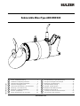
Submersible Mixer Type ABS XRW 480
15970840 EU 03.2021
Einbau- und Betriebsanleitung .......................................2 Inbouwhandleiding en gebruiksaanwijzing ...........................29
Installation and Operating Instructions ..........................5 Instrução de montagem e de utilização ............................... 32
Instructions de montage et d‘utilisation .........................8 Monterings- og bruksanvisning ............................................35
Istruzioni di montaggio e d‘uso.................................. ...11 Instrukcjamontażuiobsługi ................................................ .38
Instrucciones de Instalación y Funcionamiento. ..........14 Paigaldus- ja kasutusjuhend ................................................ .41
Monterings- och bruksanvisning ..................................17 Beépítési és üzemeltetési útmutató ......................................44
Monterings- og betjeningsvejledning ......................... .20 Montážníaprovoznípokyny ................................................ .47
Asennus - ja käyttöohje .............................................. .23 Ръководствозамонтажиексплоатация .........................50
ΟδηγίεςΕγκατάστασηςκαιΛειτουργίας ......................26 Instrucţiunidemontajşiutilizare ......................................... .53
de nl
en pt
fr no
it pl
es et
sv hu
da cs
fi bg
el ro

2
1 Allgemeines
Grundsätzlich ist die Einbau- und Betriebsanleitung mit Art.-Nr. 6006573 (Tauchmotorrührwerke Type ABS XRW) in großen Teilen auch
für das XRW 480 gültig. Dies gilt auch für den sachgemäßen Anschluss und den sicheren Betrieb der Ex-Ausführung des
XRW 480. Gleiches gilt für die Sicherheitshinweise. Diese sind in dem separaten Heft mit der Art.-Nr. 6005591 enthalten und sind vor
der Installation und Inbetriebnahme sorgfältig zu studieren!
In dieser „Zusatz“-Einbau- und Betriebsanleitung für das Tauchmotorrührwerk Typ ABS XRW 480 sind daher nur Querverweise
bzw.dieabweichenden,zusätzlichenundproduktspezischenInformationenenthalten.
1.1 - 1.3 Einführung; Bestimmungsgemäße Verwendung; Einsatzgrenzen
Siehe Kapitel 1.1 - 1.3 der Einbau- und Betriebsanleitung 6006573.
1.4 Einsatzbereiche
DasTauchmotorrührwerkXRW480dientzumMischen,RührenundUmwälzenvonzähen,feststohaltigenFluideninKläranlagen,in
der Industrie und in der Landwirtschaft. Es ist besonders für die speziellen Anforderungen bei der Homogenisierung von Schlamm und
Kofermenten ausgelegt.
1.5 Typenschlüssel
Siehe Kapitel 1.5 der Einbau- und Betriebsanleitung 6006573. *Propellertyp = 2-Blatt-Spezialpropeller für Schlamm und Kofermente.
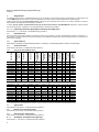
1.6 Technische Daten
Siehe Kapitel 2 der Einbau- und Betriebsanleitung 6006573.
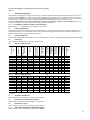
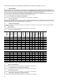
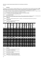
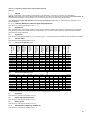
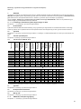
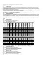
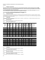
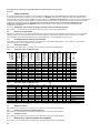
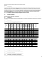
1.6.1 Technische Daten XRW 480, 50 Hz
Rührwerkstyp
Propellerdurch-
messer
Drehzahl
Motortyp
Nennleistungs-
aufnahme P1
Motornennlei-
stung P2
Nennstrom bei
400 V
Temperaturü-
berwachung
Dichtungsüber-
wachung
Ex db II BT4
Führungsrohr
□ 100
Gesamt
gewicht
[mm] [1/min] [kW/hp] [kW/hp] [A] [kg]
XRW 4811 B 480 436 PM 75/24 8,3 7,5 15,8 ● ● ○ ● 142
XRW 4812 B 480 448 PM 75/24 8,3 7,5 15,8 ● ● ○ ● 142
XRW 4813 B 480 461 PM 75/24 8,3 7,5 15,8 ● ● ○ ● 142
XRW 4814 B 480 474 PM 75/24 8,3 7,5 15,8 ● ● ○ ● 142
XRW 4811 C 480 487 PM 100/24 11,2 10,0 24,2 ● ● ○ ● 142
XRW 4812 C 480 499 PM 100/24 11,2 10,0 24,2 ● ● ○ ● 142
XRW 4813 C 480 510 PM 100/24 11,2 10,0 24,2 ● ● ○ ● 142
XRW 4814 C 480 521 PM 100/24 11,2 10,0 24,2 ● ● ○ ● 142
XRW 4815 C 480 531 PM 100/24 11,2 10,0 24,2 ● ● ○ ● 142
XRW 4816 C 480 539 PM 100/24 11,2 10,0 24,2 ● ● ○ ● 142
1.6.2 Technische Daten XRW 480, 60 Hz
XRW 4811 B 480 436 PM 75/24 8,3/11,1 7,5/10,1 15,8 ● ● ○ ● 142/313
XRW 4812 B 480 448 PM 75/24 8,3/11,1 7,5/10,1 15,8 ● ● ○ ● 142/313
XRW 4813 B 480 461 PM 75/24 8,3/11,1 7,5/10,1 15,8 ● ● ○ ● 142/313
XRW 4814 B 480 474 PM 75/24 8,3/11,1 7,5/10,1 15,8 ● ● ○ ● 142/313
XRW 4811 C 480 487 PM 100/24 11,2/15 10,0/13,4 26,4 ● ● ○ ● 142/313
XRW 4812 C 480 499 PM 100/24 11,2/15 10,0/13,4 26,4 ● ● ○ ● 142/313
XRW 4813 C 480 510 PM 100/24 11,2/15 10,0/13,4 26,4 ● ● ○ ● 142/313
XRW 4814 C 480 521 PM 100/24 11,2/15 10,0/13,4 26,4 ● ● ○ ● 142/313
XRW 4815 C 480 531 PM 100/24 11,2/15 10,0/13,4 26,4 ● ● ○ ● 142/313
XRW 4816 C 480 539 PM 100/24 11,2/15 10,0/13,4 26,4 ● ● ○ ● 142/313
P1 = Leistungsaufnahme; P2=Leistungsabgabe;●=Standard;○=Option;**Kabeltyp:10mKabelmitfreiemKabelendesindStandardlieferumfang
1.7 Typenschild
Siehe Kapitel 2.5 der Einbau- und Betriebsanleitung 6006573.
1.8 Betrieb an Frequenzumrichtern
Siehe Kapitel 10 der Einbau- und Betriebsanleitung 6006573.
1.9 Abmessungen und Gewichte
Siehe Kapitel 2.4 der Einbau- und Betriebsanleitung 6006573.
2 - 3 Sicherheit; Transport und Lagerung
Siehe Kapitel 3 - 4 der Einbau- und Betriebsanleitung 6006573.
...
480 V
Einbau- und Betriebsanleitung (Original Anleitung)
XRW 480

3
4 Produktbeschreibung
4.1 Beschreibung allgemein
Siehe Kapitel 5 der Einbau- und Betriebsanleitung 6006573.
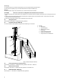
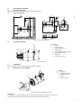
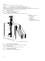
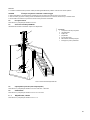
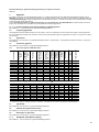
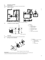
4.1.1 Baumaße XRW 480
287
[11,3]
min.190
[min.7,5]
*min.500
[min.19,7]
min.50
[min.2,0]
484
[DIA19,1]
[4,0x4,0]
100x100
286,5
[11,3]
310
[12,2]
789
[31,1]
99,5
[3,9]
100x100
40
[1,6]
484
[19,1]
[4,0x4,0]
0551-0042
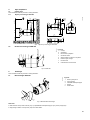
Bild 1 Baumaße XRW 480
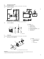
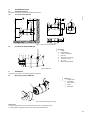
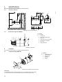
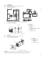
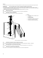
4.2 Konstruktiver Aufbau XRW 480
65 4
821
3
7
0551-0043
Legende
1 Halterung
2 Kabeleinführung
3 Halterung mit Schäkel
4 Motorgehäuse
5 Welleneinheit mit Rotor und Lagern
6 Propellernabe / Propeller
7 SD - Ring
8 Gleitringdichtung
Bild 2 XRW 480
5 Installation
Siehe Kapitel 8 der Einbau- und Betriebsanleitung 6006573.
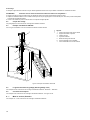
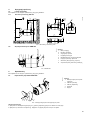
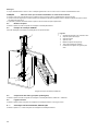
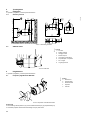
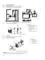
5.1 Propellermontage XRW 480
34
5
12
0551-0044
Legende
1 Zylinderschraube
2 Propellerscheibe
3 Sicherungsscheiben
4 Propeller
5 Passfeder
Bild 3 Propellermontage/-demontage

4
Demontage
• Zylinderschraube (3/1) mit Sicherungsscheiben (3/3) und Propellerscheibe (3/2) demontieren.
• Ziehen Sie den Propeller (3/4) von der Motorwelle. Entfernen Sie die Passfeder (3/5).
Montage
• Welle und Nabe reinigen. Neue Passfeder (3/5) in die Nut der Motorwelle einsetzen.
ACHTUNG Keine Öle verwenden die Molybdän-Schwefelkohlensto enthalten!
• Richten Sie die Nut der Propellernabe an der Passfeder aus und drücken Sie den Propeller vorsichtig bis zum Anschlag über die Pass-
feder.
• SetzenSiedieSicherungsscheibeund(fallszutreend)diePropellerscheibeaufdieZylinderschraube.AchtenSieaufdierichtige
Positionierung der Sicherungsscheiben.
• Ziehen Sie die Zylinderschraube auf das vorgegebene Drehmoment fest.
5.2 Anzugsmomente
Siehe Kapitel 8.2 der Einbau- und Betriebsanleitung 6006573.
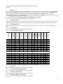
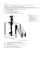
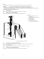
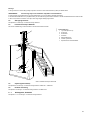
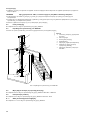
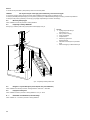
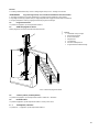
5.3 Installationsbeispiel XRW 480
Für diese Installation wird empfohlen, die geschlossene Halterung zu verwenden.
1
2
3
5
4
6
7
1581-00
Legende
1 Hebegalgen
2 Oberer Haltebock
3 Halterung geschlossen
4 Bodenlager
5 Sicherheitsklemmanschlag
6 Drehbares Vierkantleitrohr
7 Abspannklemme mit Kabelhaken
Bild 4 Installationsbeispiel XRW 480
5.4 Führungsrohrlängen (Vierkantleitrohr)
Siehe Kapitel 8.6 der Einbau- und Betriebsanleitung 6006573. XRW 480 = XRW 650.
5.5 Elektrischer Anschluß
Siehe Kapitel 9 der Einbau- und Betriebsanleitung 6006573. Siehe Bild 22/23.
6 - 7 Inbetriebnahme; Wartung
Siehe Kapitel 12 - 13 der Einbau- und Betriebsanleitung 6006573.

5
1 General
The main parts of the installation and operating instructions with part no. 6006573 (submersible mixer type ABS XRW) are also valid for XRW
480. This also applies if the XRW 480 model Ex is connected correctly and operated in safe mode. The same applies for the Safety instruc-
tions. These are included in the separate booklet 6005591 and have to be studied carefully before installation and commisioning!
These “additional” installation and operating instructions for ABS submersible mixer XRW 480 contain only cross-references e.g.
thediering,additionalandproductspecicinformation.
1.1 - 1.3 Introduction; Correct usage of the product; Application restrictions
See chapter 1.1 - 1.3 of the Installation and Operating Instructions 6006573.
1.4 Application areas
ThesubmersiblemixerXRW480isusedformixing,stirringandagitatingofviscousuidscontainingsolidsinsewagetreatmentplants,
industry,andagriculture.Itisspecicallydesignedforthemajormixingfunctionsduringhomogenizationofsludgeandcoenzymes.
1.5 Identication code
See chapter 2 of the Installation and Operating Instructions 6006573. *Propeller type = 2-blade special propeller for sludge and coen-
zymes.
1.6 Technical data
See chapter 2 of the Installation and Operating Instructions 6006573.
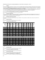
1.6.1 Technical data XRW 480, 50 Hz
Mixer type
Propeller dia-
meter
Speed / Gear
ratio
Motor type
Rated power
input P1
Rated power
output P2
Rated current
at 400 V
Temperature
monitoring
Seal monito-
ring
Ex dII BT4
Guide tube □
100
Total weight
[mm] [1/min] [kW/hp] [kW/hp] [A] [kg]
XRW 4811 B 480 436 PM 75/24 8,3 7,5 15,8 ● ● ○ ● 142
XRW 4812 B 480 448 PM 75/24 8,3 7,5 15,8 ● ● ○ ● 142
XRW 4813 B 480 461 PM 75/24 8,3 7,5 15,8 ● ● ○ ● 142
XRW 4814 B 480 474 PM 75/24 8,3 7,5 15,8 ● ● ○ ● 142
XRW 4811 C 480 487 PM 100/24 11,2 10,0 24,2 ● ● ○ ● 142
XRW 4812 C 480 499 PM 100/24 11,2 10,0 24,2 ● ● ○ ● 142
XRW 4813 C 480 510 PM 100/24 11,2 10,0 24,2 ● ● ○ ● 142
XRW 4814 C 480 521 PM 100/24 11,2 10,0 24,2 ● ● ○ ● 142
XRW 4815 C 480 531 PM 100/24 11,2 10,0 24,2 ● ● ○ ● 142
XRW 4816 C 480 539 PM 100/24 11,2 10,0 24,2 ● ● ○ ● 142
1.6.2 Technical data XRW 480, 60 Hz
XRW 4811 B 480 436 PM 75/24 8,3/11,1 7,5/10,1 15,8 ● ● ○ ● 142/313
XRW 4812 B 480 448 PM 75/24 8,3/11,1 7,5/10,1 15,8 ● ● ○ ● 142/313
XRW 4813 B 480 461 PM 75/24 8,3/11,1 7,5/10,1 15,8 ● ● ○ ● 142/313
XRW 4814 B 480 474 PM 75/24 8,3/11,1 7,5/10,1 15,8 ● ● ○ ● 142/313
XRW 4811 C 480 487 PM 100/24 11,2/15 10,0/13,4 26,4 ● ● ○ ● 142/313
XRW 4812 C 480 499 PM 100/24 11,2/15 10,0/13,4 26,4 ● ● ○ ● 142/313
XRW 4813 C 480 510 PM 100/24 11,2/15 10,0/13,4 26,4 ● ● ○ ● 142/313
XRW 4814 C 480 521 PM 100/24 11,2/15 10,0/13,4 26,4 ● ● ○ ● 142/313
XRW 4815 C 480 531 PM 100/24 11,2/15 10,0/13,4 26,4 ● ● ○ ● 142/313
XRW 4816 C 480 539 PM 100/24 11,2/15 10,0/13,4 26,4 ● ● ○ ● 142/313
P1 =Power input; P2=Poweroutput;●=Standard;○=Option;Cabletype:10mcablewithfreeendsasstandard.
1.7 Nameplate
See chapter 2.5 of the Installation and Operating Instructions 6006573.
1.8 Operation with frequency inverters
See chapter 10 of the Installation and Operating Instructions 6006573.
1.9 Dimensions and weights
See chapter 2.4 of the Installation and Operating Instructions 6006573.
2 - 3 Safety; Transport and storage
See chapter 3 - 4 of the Installation and Operating Instructions 6006573.
...
480 V
Installation and Operating Instructions (Translation of Original Instructions)
XRW 480

6
4 Product description
4.1 General description
See chapter 5 of the Installation and Operating Instructions 6006573.
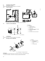
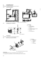
4.1.1 Dimensions XRW 480
287
[11,3]
min.190
[min.7,5]
*min.500
[min.19,7]
min.50
[min.2,0]
484
[DIA19,1]
[4,0x4,0]
100x100
286,5
[11,3]
310
[12,2]
789
[31,1]
99,5
[3,9]
100x100
40
[1,6]
484
[19,1]
[4,0x4,0]
0551-0042
Figure 1 Dimensions XRW 480
4.2 Structural design XRW 480
65 4
82
1
3
7
0551-0043
Legend
1 Bracket
2 Cable inlet
3 Bracket with shackle
4 Motor housing
5 Shaft unit with rotor and bearings
6 Propeller boss / propeller
7 SD ring
8 Mechanical seal
Figure 2 XRW 480
5 Installation
See chapter 8 of the Installation and Operating Instructions 6006573.
5.1 Propeller assembly XRW 480
34
5
12
0551-0044
Legend
1 Socket head screw
2 Propeller washer
3 Lock washers
4 Propeller
5 Shaft key
Figure 3 Propeller assembly/dismantling
Dismantling
• Dismantle socket head screw (3/1) with lock washers (3/3) and propeller washer (3/2).
• Withdraw the propeller (3/4) from the propeller shaft. Remove key (3/5) from the end of the shaft.

7
Assembly
• Clean carefully shaft and boss. the key to the shaft end.
ATTENTION Do not use any products containing molybdenum disulphide!
• Bring the groove of the propeller hub into line with the shaft key and push the propeller carefully to a stop.
• Fitthesecuringwasherandthepropellerwasher(whereapplicable)tothesocketheadscrew.Ensurethecorrectttingpositionofthe
securing washers.
• Screwinthesocketheadscrewandtightenittothespeciedtighteningtorque.
5.2 Tightening torque
See chapter 8.2 of the Installation and Operating Instructions 6006573.
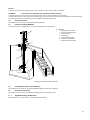
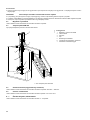
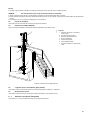
5.3 Installation example XRW 480
We recommend that the closed bracket be used for this type of installation
1
2
3
5
4
6
7
1581-00
Legend
1 Hoist with winch and rope
2 Upper bracket with locking plate
3 Closed bracket
4 Bottom plate
5 Safety stop clamp
6 Swivellingsquareguidetube
7 Cable clamp with cable hook
Figure 4 Installation example XRW 480
5.4 Guide tube lengths (square tube)
See chapter 8.6 of the Installation and Operating Instructions 6006573. XRW 480 = XRW 650.
5.5 Electrical connection
See chapter 9 of the Installation and Operating Instructions 6006573. See gure 22/23.
6 - 7 Commissioning; Maintenance
See chapter 12 - 13 of the Installation and Operating Instructions 6006573.

8
1 Généralités
De manière générale, la notice de montage et d'utilisation, réf. 6006573 (Agitateur submersible type ABS XRW) est également valable
pour le modèle XRW 480. Ceci vaut également pour le raccordement conforme et le fonctionnement sûr du modèle Ex du
XRW 480. Il en est de même pour les consignes de sécurité.Celles-cigurentdansundocumentséparé,réf.6005591,etdoiventêtre
soigneusement étudiées avant l'installation et la mise en service !
Cette notice de montage et d'utilisation « supplémentaire » pour l'agitateur à moteur submersible XRW 480 comprend en outre
uniquementdesréférencescroiséesoudesinformationsdérivées,supplémentairesetspéciquesauproduit.
1.1 - 1.3 Introduction; Utilisation conforme; Limites d’utilisation des unités
Voir Chapitre 1.1 - 1.3 de l’Instructions de montage et d'utilisation 6006573.
1.4 Domaines d‘application
L'agitateuràmoteursubmersibleXRW480sertàmélanger,agiteretbrasserlesuidesvisqueuxetsolidesdanslesstationsd'épuration,
dans l'industrie et dans l'agriculture. Il a été spécialement conçu pour les exigences spéciales en matière d'homogénéisation de la boue
et des co-ferments/co-substrats.
1.5 Codes de types
Voir Chapitre 1.5 de l’Instructions de montage et d'utilisation 6006573. *Type d‘hélice = Hélice spéciale 2-pales pour la boue et les co-
ferments/co-substrats.
1.6 Caractéristiques techniques
Voir Chapitre 2 de l’Instructions de montage et d'utilisation 6006573.
1.6.1 Caractéristiques techniques XRW 480, 50 Hz
Type
d‘agitateur
Diamètre
d’hélice
Vitesse / Ré-
ducteur
Type de mo-
teur
Puissance nomi-
nale absorbée
P1
Puissance nomi-
nale du moteur P2
Courant nomi-
nal à 400 V
Contrôle de
température
Contrôle de
l’étanchéité
Ex dII BT4
Tube de guida-
ge □ 100
Poids total
[mm] [1/min] [kW/hp] [kW/hp] [A] [kg]
XRW 4811 B 480 436 PM 75/24 8,3 7,5 15,8 ● ● ○ ● 142
XRW 4812 B 480 448 PM 75/24 8,3 7,5 15,8 ● ● ○ ● 142
XRW 4813 B 480 461 PM 75/24 8,3 7,5 15,8 ● ● ○ ● 142
XRW 4814 B 480 474 PM 75/24 8,3 7,5 15,8 ● ● ○ ● 142
XRW 4811 C 480 487 PM 100/24 11,2 10,0 24,2 ● ● ○ ● 142
XRW 4812 C 480 499 PM 100/24 11,2 10,0 24,2 ● ● ○ ● 142
XRW 4813 C 480 510 PM 100/24 11,2 10,0 24,2 ● ● ○ ● 142
XRW 4814 C 480 521 PM 100/24 11,2 10,0 24,2 ● ● ○ ● 142
XRW 4815 C 480 531 PM 100/24 11,2 10,0 24,2 ● ● ○ ● 142
XRW 4816 C 480 539 PM 100/24 11,2 10,0 24,2 ● ● ○ ● 142
1.6.2 Caractéristiques techniques XRW 480, 60 Hz
XRW 4811 B 480 436 PM 75/24 8,3/11,1 7,5/10,1 15,8 ● ● ○ ● 142/313
XRW 4812 B 480 448 PM 75/24 8,3/11,1 7,5/10,1 15,8 ● ● ○ ● 142/313
XRW 4813 B 480 461 PM 75/24 8,3/11,1 7,5/10,1 15,8 ● ● ○ ● 142/313
XRW 4814 B 480 474 PM 75/24 8,3/11,1 7,5/10,1 15,8 ● ● ○ ● 142/313
XRW 4811 C 480 487 PM 100/24 11,2/15 10,0/13,4 26,4 ● ● ○ ● 142/313
XRW 4812 C 480 499 PM 100/24 11,2/15 10,0/13,4 26,4 ● ● ○ ● 142/313
XRW 4813 C 480 510 PM 100/24 11,2/15 10,0/13,4 26,4 ● ● ○ ● 142/313
XRW 4814 C 480 521 PM 100/24 11,2/15 10,0/13,4 26,4 ● ● ○ ● 142/313
XRW 4815 C 480 531 PM 100/24 11,2/15 10,0/13,4 26,4 ● ● ○ ● 142/313
XRW 4816 C 480 539 PM 100/24 11,2/15 10,0/13,4 26,4 ● ● ○ ● 142/313
P1 =Puissance absorbée; P2=Puissancedébitée;●=Standard;○=Option;Typedecâble:10mdecâbleavecextrémitélibrefontpartiedelafourni-
ture standard
1.7 Plaque signalétique de type
Voir Chapitre 2.5 de l’Instructions de montage et d‘utilisation 6006573.
1.8 Fonctionnement avec convertisseurs de fréquence
Voir Chapitre 10 de l’Instructions de montage et d‘utilisation 6006573.
1.9 Dimensions et poids
Voir Chapitre 2.4 de l’Instructions de montage et d'utilisation 6006573.
2 - 3 Sécurité; Transport et mise en place
Voir Chapitre 3 - 4 de l’Instructions de montage et d‘utilisation 6006573.
...
480 V
Instructions de montage et d‘utilisation (Traduction des consignes d‘origine) - XRW 480

9
4 Description du produit
4.1 Description générale
Voir Chapitre 5 de l’Instructions de montage et d‘utilisation 6006573.
4.1.1 Dimensions XRW 480
287
[11,3]
min.190
[min.7,5]
*min.500
[min.19,7]
min.50
[min.2,0]
484
[DIA19,1]
[4,0x4,0]
100x100
286,5
[11,3]
310
[12,2]
789
[31,1]
99,5
[3,9]
100x100
40
[1,6]
484
[19,1]
[4,0x4,0]
0551-0042
Figure 1 Dimensions XRW 480
4.2 Conception XRW 480
65 4
821
3
7
0551-0043
Légende
1 Fixation
2 Entréedecâble
3 Support avec manille
4 Carter-moteur
5 Unité d‘arbre avec rotor et paliers
6 Moyeu d‘hélice / Hélice
7 Bague SD
8 Garnituremécanique
Figure 2 XRW 480
5 Installation
Voir Chapitre 8 de l’Instructions de montage et d'utilisation 6006573.
5.1 Montage de l‘hélice XRW 480
34
5
12
0551-0044
Légende
1 Vis à tête
2 Rondelle de l‘hélice
3 Rondelles d‘arrêt
4 Hélice
5 Clavette d’arbre
Figure 3 Montage / Démontage de l‘hélice
Démontage
• Desserrerlavisàtêtecylindrique(3/1)aveclesrondellesd'arrêt(3/3)etlarondelledel‘hélice(3/2).
• Enlever l’hélice de l’arbre d’hélice. Retirer la clavette (3/5) de l’extrémité de l’arbre.

10
Assemblage
• Nettoyer soigneusement l’arbre et le moyeu. Huiler légèrement l’arbre et le moyeu. Mettre la clavette sur l’extrémité de l’arbre.
ATTENTION N'utiliser aucune huile contenant du sulfure de carbone au molybdène !
• Aligner la gorge du moyeu de l’hélice avec la clavette de l’arbre et pousser soigneusement l’hélice à l’arrêt.
• Adapterlarondelledexationetlarondelled’hélice(suivantcequis’applique)àlavisdetêtedeprise.Assurerlapositiond’adaptation
correctedesrondellesdexation.
• Visserlavisdetêtedepriseetlaserrerselonlecoupledeserragespécié.
5.2 Couple des serrage
Voir paragraphe 8.2 d‘Instructions de montage et d‘utilisation 6006573.
5.3 Exemple d‘installation XRW 480
Pourcetyped‘installationnousrecommandonsd‘utiliserlaxationfermée
1
2
3
5
4
6
7
1581-00
Légende
1 Potencedelevageavectreuiletcâble
2 Supportdexationsupérieur
3 Fixation fermée
4 Logement inférieur
5 Butée de serrage de sécurité
6 Tube de guidage carré orientable
7
Pinced‘extrémitéaveccrochetdecâble
Figure 4 Exemple d‘installation XRW 480
5.4 Longueurs des tubes de guidage (tube de guidage carré)
Voir Chapitre 8.6 de l’Instructions de montage et d'utilisation 6006573. XRW 480 = XRW 650.
5.5 Connections électriques
Voir Chapitre 9 de l’Instructions de montage et d'utilisation 6006573. Voir gure 22/23.
6 - 7 Mise en service; Entretien
Voir Chapitre 12 - 13 de l’Instructions de montage et d'utilisation 6006573.

11
1 Informazioni generali
Sostanzialmente le istruzioni di montaggio e d'uso dell'Art. Nr. 6006573 (Miscelatori sommersi tipo ABS XRW) valgono in gran parte
anche per l'agitatore XRW 480. Lo stesso vale per il corretto collegamento e il funzionamento sicuro dell‘XRW 480 in esecuzione per
atmosfere a rischio di esplosione. Lo stesso dicasi per le avvertenze di sicurezza. Queste sono contenute in un opuscolo separato con
l'Art. Nr. 6005591 e debbono essere lette e studiate attentamente prima dell'installazione e della messa in funzione!
Nel presente "Supplemento" delle istruzioni montaggio e d'uso per l' ABS agitatori a motore sommerso XRW 480sonoquindi
contenutisolorimandinonchéinformazionisupplementariespecichedelprodotto.
1.1 - 1.3 Introduzione; Utilizzo conforme; Limiti d‘impiego
Vedere capitolo 1.1 - 1.3 delle istruzioni di montaggio e d'uso 6006573.
1.4 Campi d‘applicazione
L'agitatoreamotoresommersoXRW480servepermescolare,girareerimestareuididensicontenentisostanzesolidepresentinegli
impianti di depurazione, in uso nell'industria e nell'agricoltura. Esso è stato progettato appositamente per soddisfare le particolari ri-
chieste di omogenizzazione di fanghi e cofermenti/substrati.
1.5 Codici identicativi
Vedere capitolo 1.5 delle istruzioni di montaggio e d'uso 1 597 0832-EU/0833-EU. *Tipo elica = Elica speciale a 2 pale per fanghi e cofermenti/substrati.
1.6 Dati tecnici
Vedere capitolo 2 delle istruzioni di montaggio e d'uso 6006573.
1.6.1 Dati tecnici XRW 480, 50 Hz
Tipo miscela-
tore
Diametro elica
Numero di giri /
Riduzione
Tipo motore
Assorbimento di
potenza nominale P
1
Potenza nomi-
nale motore P2
Corrente nomi-
nale a 400 V
Monitoraggio
temperatura
Monitoraggio
tenuta stagna
Ex dII BT4
Guida tubolare
□ 100
Peso comples-
sivo
[mm] [1/min] [kW/hp] [kW/hp] [A] [kg]
XRW 4811 B 480 436 PM 75/24 8,3 7,5 15,8 ● ● ○ ● 142
XRW 4812 B 480 448 PM 75/24 8,3 7,5 15,8 ● ● ○ ● 142
XRW 4813 B 480 461 PM 75/24 8,3 7,5 15,8 ● ● ○ ● 142
XRW 4814 B 480 474 PM 75/24 8,3 7,5 15,8 ● ● ○ ● 142
XRW 4811 C 480 487 PM 100/24 11,2 10,0 24,2 ● ● ○ ● 142
XRW 4812 C 480 499 PM 100/24 11,2 10,0 24,2 ● ● ○ ● 142
XRW 4813 C 480 510 PM 100/24 11,2 10,0 24,2 ● ● ○ ● 142
XRW 4814 C 480 521 PM 100/24 11,2 10,0 24,2 ● ● ○ ● 142
XRW 4815 C 480 531 PM 100/24 11,2 10,0 24,2 ● ● ○ ● 142
XRW 4816 C 480 539 PM 100/24 11,2 10,0 24,2 ● ● ○ ● 142
1.6.2 Dati tecnici XRW 480, 60 Hz
XRW 4811 B 480 436 PM 75/24 8,3/11,1 7,5/10,1 15,8 ● ● ○ ● 142/313
XRW 4812 B 480 448 PM 75/24 8,3/11,1 7,5/10,1 15,8 ● ● ○ ● 142/313
XRW 4813 B 480 461 PM 75/24 8,3/11,1 7,5/10,1 15,8 ● ● ○ ● 142/313
XRW 4814 B 480 474 PM 75/24 8,3/11,1 7,5/10,1 15,8 ● ● ○ ● 142/313
XRW 4811 C 480 487 PM 100/24 11,2/15 10,0/13,4 26,4 ● ● ○ ● 142/313
XRW 4812 C 480 499 PM 100/24 11,2/15 10,0/13,4 26,4 ● ● ○ ● 142/313
XRW 4813 C 480 510 PM 100/24 11,2/15 10,0/13,4 26,4 ● ● ○ ● 142/313
XRW 4814 C 480 521 PM 100/24 11,2/15 10,0/13,4 26,4 ● ● ○ ● 142/313
XRW 4815 C 480 531 PM 100/24 11,2/15 10,0/13,4 26,4 ● ● ○ ● 142/313
XRW 4816 C 480 539 PM 100/24 11,2/15 10,0/13,4 26,4 ● ● ○ ● 142/313
P1 = Potenza assorbita; P2=Potenzaerogata;●=Standard;○=Optional;Tipodicavo:ladotazionestandardprevedecavida10mconestremi-
tà cavo libera
1.7 Targhetta identicativa
Vedere capitolo 2.5 delle istruzioni di montaggio e d‘uso 6006573.
1.8 Esercizio su convertitori di frequenza
Vedere capitolo 10 delle istruzioni di montaggio e d‘uso 6006573.
1.9 Dimensione e peso
Vedere capitolo 2.4 delle istruzioni di montaggio e d'uso 6006573.
2 - 3 Sicurezza; Trasporto e immagazzinaggio
Vedere capitolo 3 - 4 delle istruzioni di montaggio e d‘uso 6006573.
...
480 V
Istruzioni di montaggio e d‘uso (Traduzione delle istruzioni originali)
XRW 480

12
4 Descrizione del prodotto
4.1 Descrizione in genere
Vedere capitolo 5 delle istruzioni di montaggio e d‘uso 6006573.
4.1.1 Dimensioni XRW 480
287
[11,3]
min.190
[min.7,5]
*min.500
[min.19,7]
min.50
[min.2,0]
484
[DIA19,1]
[4,0x4,0]
100x100
286,5
[11,3]
310
[12,2]
789
[31,1]
99,5
[3,9]
100x100
40
[1,6]
484
[19,1]
[4,0x4,0]
0551-0042
Fig. 1 Dimensioni XRW 480
4.2 Struttura costruttiva XRW 480
65 4
821
3
7
0551-0043
Legenda
1 Supporto
2 Introduzione cavo
3 Supporto con maniglia
4 Corpo motore
5 Unità albero con rotore e cuscinetti
6 Mozzo dell‘elica / Elica
7 Anello SD
8 Guarnizione ad anello scorrevole
Fig. 2 XRW 480
5 Installazione
Vedere capitolo 8 delle istruzioni di montaggio e d'uso 6006573.
5.1 Montaggio dell‘elica XRW 480
34
5
12
0551-0044
Legenda
1 Vite a testa cilindrica
2 Disco dell‘elica
3 Rondelle di sicurezza
4 Elica
5 Chiavetta albero
Fig. 3 Montaggio e smontaggio dell'elica
Smontaggio
• Smontare la vite a testa cilindrica (3/1) con rosette di sicurezza (3/3), rondella dell'elica (3/2).
• Estrarre l’elica dall’albero. Rimuovere la chiavetta (3/5) dall’estremità dell’albero.

13
Montaggio
• Pulire con cura albero e mozzo. Oliare leggermente albero e mozzo. Inserire la chiavetta nell’estremità dell’albero.
ATTENZIONE Non usare oli contenenti molibdeno e zolfo!
• Portarelascanalaturadelmozzodell’elicainlineaconlachiavettadell’alberoespingerel’elicaconcautelanoall’arresto.
• Far corrispondere la rondella autobloccante e la rondella dell’elica (se presente) alla vite a testa cilindrica. Assicurare la corretta posizi-
one di corrispondenza delle rondelle autobloccanti.
• Avvitarelaviteatestacilindricaeserrarlaconilmomentodiserraggiospecicato.
5.2 Coppie di serraggio
Vedere capitolo 8.2 delle istruzioni di montaggio e d'uso 6006573.
5.3 Esempi di installazione XRW 480
Perquestotipodiinstallazionesisuggeriscediutilizzareilsupportochiuso.
1
2
3
5
4
6
7
1581-00
Legenda
1 „Braccio“ da sollevamento con verri
cello e cavo
2 Cavalletto di supporto superiore
3 Supporto chiuso
4 Cuscinetti pavimento
5 Finecorsadissaggiodisicurezza
6 Tubazionequadragirevole
7 Dispositivo di ancoraggio con cavo e
gancio
Fig. 4 Esempi di installazione XRW 480
5.4 Lunghezze delle guide tubolari (tubazioni quadre)
Vedere capitolo 8.6 delle istruzioni di montaggio e d'uso 6006573. XRW 480 = XRW 650.
5.5 Collegamento elettrico
Vedere capitolo 9 delle istruzioni di montaggio e d'uso 6006573. Vedere Fig.22/23.
6 - 7 Messa in esercizio; Manutenzione
Vedere capitolo 12 - 13 delle istruzioni di montaggio e d'uso 6006573.

14
1 Generalidades
El manual de instrucciones de instalación y funcionamiento con nº de referencia 6006573 (Agitador Sumergible Gama ABS XRW) es
también válido para los componentes principales del agitador modelo XRW 480. Esto vale también para la conexión adecuada y el fun-
cionamientosegurodelavarianteExdelXRW480,aligualquelasInstrucciones generales de Seguridad cuyo documento con nº de
referencia15970799debeestudiarseatentamenteantesdelainstalaciónylapuestaenmarcadelequipo.
Estas instrucciones “adicionales” para el agitador sumergible XRW 480 corresponden a referencias cruzadas relacionada con
informaciónqueseaespecíca,adicionalodiferenteparaesteequipoenconcreto.
1.1 - 1.3 Introducción; Uso adecuado; Limitaciones
Ver apartado 1.1 - 1.3 de las Instrucciones de Instalación y Funcionamiento – Ref. 6006573.
1.4 Áreas de aplicación
ElagitadorsumergibleXRW480esidóneoparalamezclayagitacióndeuídosviscososconcontenidossólidosenplantasdetrata-
miento de aguas residuales, así como en la industria y en la agricultura. Está especialmente diseñado para las principales funciones de
agitación durante el proceso de homogeneización de lodos y coencimas.
1.5 Código de identicación
Ver apartado 1.5 de las Instrucciones de Instalación y Funcionamiento – Ref. 6006573. *Tipo de hélice = Hélice especial de 2 álabes
para lodos y coencimas.
1.6 Datos técnicos
Ver apartado 2 de las Instrucciones de Instalación y Funcionamiento – Ref. 6006573.
1.6.1 Datos técnicos XRW 480, 50 Hz
Modelo
agitador
Diámetro
hélice
Velocidad /
Desmultiplica-
ción
Tipo de motor
Potencia
absorbida P1
Potencia en el
eje P2
Intensidad no-
minal a 400 V
Control de
temperatura
Detector de
humedad
Ex dII BT4
Tubo guía
□ 100
Peso total
[mm] [1/min] [kW/hp] [kW/hp] [A] [kg]
XRW 4811 B 480 436 PM 75/24 8,3 7,5 15,8 ● ● ○ ● 142
XRW 4812 B 480 448 PM 75/24 8,3 7,5 15,8 ● ● ○ ● 142
XRW 4813 B 480 461 PM 75/24 8,3 7,5 15,8 ● ● ○ ● 142
XRW 4814 B 480 474 PM 75/24 8,3 7,5 15,8 ● ● ○ ● 142
XRW 4811 C 480 487 PM 100/24 11,2 10,0 24,2 ● ● ○ ● 142
XRW 4812 C 480 499 PM 100/24 11,2 10,0 24,2 ● ● ○ ● 142
XRW 4813 C 480 510 PM 100/24 11,2 10,0 24,2 ● ● ○ ● 142
XRW 4814 C 480 521 PM 100/24 11,2 10,0 24,2 ● ● ○ ● 142
XRW 4815 C 480 531 PM 100/24 11,2 10,0 24,2 ● ● ○ ● 142
XRW 4816 C 480 539 PM 100/24 11,2 10,0 24,2 ● ● ○ ● 142
1.6.2 Datos técnicos XRW 480, 60 Hz
XRW 4811 B 480 436 PM 75/24 8,3/11,1 7,5/10,1 15,8 ● ● ○ ● 142/313
XRW 4812 B 480 448 PM 75/24 8,3/11,1 7,5/10,1 15,8 ● ● ○ ● 142/313
XRW 4813 B 480 461 PM 75/24 8,3/11,1 7,5/10,1 15,8 ● ● ○ ● 142/313
XRW 4814 B 480 474 PM 75/24 8,3/11,1 7,5/10,1 15,8 ● ● ○ ● 142/313
XRW 4811 C 480 487 PM 100/24 11,2/15 10,0/13,4 26,4 ● ● ○ ● 142/313
XRW 4812 C 480 499 PM 100/24 11,2/15 10,0/13,4 26,4 ● ● ○ ● 142/313
XRW 4813 C 480 510 PM 100/24 11,2/15 10,0/13,4 26,4 ● ● ○ ● 142/313
XRW 4814 C 480 521 PM 100/24 11,2/15 10,0/13,4 26,4 ● ● ○ ● 142/313
XRW 4815 C 480 531 PM 100/24 11,2/15 10,0/13,4 26,4 ● ● ○ ● 142/313
XRW 4816 C 480 539 PM 100/24 11,2/15 10,0/13,4 26,4 ● ● ○ ● 142/313
P
1
= Potencia absorbida; P
2
=Potenciaeneleje;●=Standard;○=Opcional;Tipodecable:10mdecableconlosextremoslibresincluidoenelsuministro
standard.
1.7 Placa de características
Ver apartado 2.5 de las Instrucciones de Instalación y Funcionamiento – Ref. 6006573.
1.8 Funcionamiento con variadores de frecuencia
Ver apartado 10 de las Instrucciones de Instalación y Funcionamiento – Ref. 6006573
1.9 Dimensiones y pesos
Ver apartado 2.4 de las Instrucciones de Instalación y Funcionamiento – Ref. 6006573.
2 - 3 Seguridad; Transporte y almacenamiento
Ver apartado 3 - 4 de las Instrucciones de Instalación y Funcionamiento – Ref. 6006573.
...
480 V
Instrucciones de Instalación y Funcionamiento (Traducción de las instrucciones originales) - XRW 480

15
4 Descripción del equipo
4.1 Descripción general
Ver apartado 5 de las Instrucciones de Instalación y Funcionamiento – Ref. 6006573.
4.1.1 Dimensiones XRW 480
287
[11,3]
min.190
[min.7,5]
*min.500
[min.19,7]
min.50
[min.2,0]
484
[DIA19,1]
[4,0x4,0]
100x100
286,5
[11,3]
310
[12,2]
789
[31,1]
99,5
[3,9]
100x100
40
[1,6]
484
[19,1]
[4,0x4,0]
0551-0042
Bild 1 Baumaße XRW 480
4.2 Diseño de XRW 480
65 4
821
3
7
0551-0043
Leyenda
1 Soporte guía
2 Entrada de cable
3 Soporte con grillete
4 Alojamiento del motor
5 Eje + Rotor y rodamientos
6 Protector tornillo de la hélice / hélice
7 Anillodeector(SD)
8 Junta mecánica
Fig. 2 XRW 480
5 Instalación
Ver apartado 8 de las Instrucciones de Instalación y Funcionamiento – Ref. 6006573.
5.1 Montaje de la hélice XRW 480
34
5
12
0551-0044
Leyenda
1 Tornillo de cabeza hueca
2 Arandela de la hélice
3 Arandelasdebloqueo
4 Hélice
5 Chaveta del eje
Fig. 3 Montaje/desmontaje de la hélice
Desmontaje
• Retirareltornillodecabezahueca(3/1)conlasarandelasdebloqueo(3/3),laarandeladelahélice(3/2).
• Separe la hélice del eje. Extraiga la chaveta (3/5) del extremo del eje.

16
Montaje
• Limpiecuidadosamenteelejeylabrida.Lubríquelosligeramente.Montelachavetaenelextremodeleje.
ATENCIÓN ¡No utilizar ningún producto que contenga bisulfuro de molibdeno!
• Alinee la ranura del cubo de la hélice con la chaveta del eje y empuje la hélice cuidadosamente hasta el tope.
• FColoquelaarandeladeseguridadylaarandeladelahélice(siprocede)eneltornilloAllen.Asegúresedequelasarandelasde
seguridadquedencolocadascorrectamente.
• EnrosqueeltornilloAllenyapriételoalparespecicado.
5.2 Pares de apriete
Ver apartado 8.2 de las Instrucciones de Instalación y Funcionamiento – Ref. 6006573.
5.3 Ejemplo de instalación de XRW 480
Para este tipo de instalación, recomendamos la utilización del soporte guía cerrado.
1
2
3
5
4
6
7
1581-00
Leyenda
1 Elemento de elevación con torno
mural y cable
2 Soportesuperiorconplacadebloqueo
3 Soporte guía cerrado
4 Placa de anclaje
5 Tope de seguridad
6 Tubo guía cuadrado giratorio
7 Abrazadera y gancho para el cable
Fig. 4 Ejemplo de instalación de XRW 480
5.4 Longitud de los tubos guía (forma cuadrada)
Ver apartado 8.6 de las Instrucciones de Instalación y Funcionamiento – Ref. 6006573. XRW 480 = XRW 650.
5.5 Conexión eléctrica
Ver apartado 9 de las Instrucciones de Instalación y Funcionamiento – Ref. 6006573. Ver g. 22/23.
6 - 7 Puesta en servicio; Mantenimiento
Ver apartado 12 - 13 de las Instrucciones de Instalación y Funcionamiento – Ref. 6006573.

17
1 Allmänt
I princip gäller inmonterings- och bruksanvisning med art.-Nr. 6006573 (Dränkbar mixer typ ABS RW) itill största delen också för
XRW 480. Detta gäller också för den korrekta anslutningen och säker drift av Ex-utförandet av XRW 480. Det samma gäller också för Säker-
hetsanvisningarna.Dessannsiettseparathäftemedart.-Nr.6005591ochskastuderasnogainnaninstallationochidriftsättning!
I denna "Tillsats"-monterings- och bruksanvisning för ABS dränkbar pump-omrörare XRW 480nnsdärförbarareferenshänvis-
ningarresp.avvikande,kompletterandeochproduktspecikainformationer.
1.1 - 1.3 Inledning; Avsedd användning; Användningsbegränsningar
Se kapitel 1.1 - 1.3 i monterings- och bruksanvisning 6006573.
1.4 Användningsområden
Dränkmotoromröringsverk XRW 480 tjänar till blandning, omröring och cirkulation av sega, fasta medier i reningsanläggningar, inom
industri och lantbruk. Det är speciellt konstruerat för de speciella kraven vid homogenisering av slamm och kofermenter/kosubstrater.
1.5 Typnyckel
Se kapitel 1.5 i monterings- och bruksanvisning 6006573. *Propellertyp = 2-blads specialpropeller för slamm och kofermenter/kosubstra-
ter.
1.6 Tekniska data
Se kapitel 2 i monterings- och bruksanvisning 6006573.
1.6.1 Tekniska data XRW 480, 50 Hz
Omrörartyp
Propellerdia-
meter
Varvtal / Dri-
vutväxling
Motortyp
Angiven eekt-
förbrukning P1
Angiven mo-
toreekt P2
Angiven ströms-
tyrka vid 400 V
Temperaturö-
vervakning
Tätningsover-
vakning
Ex dII BT4
Gejdrör □ 100
Totalvikt
[mm] [1/min] [kW/hp] [kW/hp] [A] [kg]
XRW 4811 B 480 436 PM 75/24 8,3 7,5 15,8 ● ● ○ ● 142
XRW 4812 B 480 448 PM 75/24 8,3 7,5 15,8 ● ● ○ ● 142
XRW 4813 B 480 461 PM 75/24 8,3 7,5 15,8 ● ● ○ ● 142
XRW 4814 B 480 474 PM 75/24 8,3 7,5 15,8 ● ● ○ ● 142
XRW 4811 C 480 487 PM 100/24 11,2 10,0 24,2 ● ● ○ ● 142
XRW 4812 C 480 499 PM 100/24 11,2 10,0 24,2 ● ● ○ ● 142
XRW 4813 C 480 510 PM 100/24 11,2 10,0 24,2 ● ● ○ ● 142
XRW 4814 C 480 521 PM 100/24 11,2 10,0 24,2 ● ● ○ ● 142
XRW 4815 C 480 531 PM 100/24 11,2 10,0 24,2 ● ● ○ ● 142
XRW 4816 C 480 539 PM 100/24 11,2 10,0 24,2 ● ● ○ ● 142
1.6.2 Tekniska data XRW 480, 60 Hz
XRW 4811 B 480 436 PM 75/24 8,3/11,1 7,5/10,1 15,8 ● ● ○ ● 142/313
XRW 4812 B 480 448 PM 75/24 8,3/11,1 7,5/10,1 15,8 ● ● ○ ● 142/313
XRW 4813 B 480 461 PM 75/24 8,3/11,1 7,5/10,1 15,8 ● ● ○ ● 142/313
XRW 4814 B 480 474 PM 75/24 8,3/11,1 7,5/10,1 15,8 ● ● ○ ● 142/313
XRW 4811 C 480 487 PM 100/24 11,2/15 10,0/13,4 26,4 ● ● ○ ● 142/313
XRW 4812 C 480 499 PM 100/24 11,2/15 10,0/13,4 26,4 ● ● ○ ● 142/313
XRW 4813 C 480 510 PM 100/24 11,2/15 10,0/13,4 26,4 ● ● ○ ● 142/313
XRW 4814 C 480 521 PM 100/24 11,2/15 10,0/13,4 26,4 ● ● ○ ● 142/313
XRW 4815 C 480 531 PM 100/24 11,2/15 10,0/13,4 26,4 ● ● ○ ● 142/313
XRW 4816 C 480 539 PM 100/24 11,2/15 10,0/13,4 26,4 ● ● ○ ● 142/313
P1=uppmätteektförbrukning;P2=eektuttag;●=standard;○=tillvall;Kabeltyp:10mkabelmedfriaändaristandardutförande
1.7 Typskylt
Se kapitel 2.5 i monterings- och bruksanvisning 6006573.
1.8 Drift med frekvensomformare
Se kapitel 10 i monterings- och bruksanvisning 6006573.
1.9 Mått och vikter
Se kapitel 2.4 i monterings- och bruksanvisning 6006573.
2 - 3 Säkerhet; Transport och lagring
Se kapitel 3- 4 i monterings- och bruksanvisning 6006573.
...
480 V
Monterings- och bruksanvisning (Översättning av originalinstruktioner)
XRW 480

18
4 Produktbeskrivning
4.1 Generell beskrivning
Se kapitel 5 i monterings- och bruksanvisning 6006573.
4.1.1 Måttdata XRW 480
287
[11,3]
min.190
[min.7,5]
*min.500
[min.19,7]
min.50
[min.2,0]
484
[DIA19,1]
[4,0x4,0]
100x100
286,5
[11,3]
310
[12,2]
789
[31,1]
99,5
[3,9]
100x100
40
[1,6]
484
[19,1]
[4,0x4,0]
0551-0042
Bild 1 Måttdata XRW 480
4.2 Konstruktion för XRW 480
65 4
821
3
7
0551-0043
Teckenförklaring
1 Fäste
2 Kabelgenomföring
3 Hållare med schackel
4 Motorghus
5 Axelenhet med rotor och lager
6 Propellernav / Propeller
7 SD - ring
8 Glidringstätning
Bild 2 XRW 480
5 Installation
Se kapitel 8 i monterings- och bruksanvisning 6006573.
5.1 Propellermontering XRW 480
34
5
12
0551-0044
Teckenförklaring
1 Cylinderskruv
2 Propellerplatta
3 Låsbrickor
4 Propeller
5 Skaftnyckel
Bild 3 Propellermontage/-demontage
Demontage
• Demontera cylinderskruv (3/1) med Låsbrickor (3/3), och propellerplatta (3/2).
• Dra ut propellern från propellerskaftet. Ta bort nyckeln (3/5) från skaftets ände.

19
Montage
• Rengör skaft och centrumdel grundligt. Olja lätt in skaft och centrumdel. Montera nyckeln på skaftets ände.
OBSERVERA Använd inga oljor som innehåller molybden-svavelkolämnen!
• Rikta in spåret på propellernavet i linje med skaftnyckeln och tryck propellern försiktigt till stoppet.
• Monterasäkerhetsbrickanochpropellerbrickan(omensådannns)påsockelnshuvudskruv.Setillattsäkerhetsbrickornasitterkorrekt.
• Skruva in sockelns huvudskruv och spänn den enligt angivet åtdragningsmoment.
5.2 Åtdragningsmoment
Se kapitel 8.2 i monterings- och bruksanvisning 6006573.
5.3 Installationsexempel XRW 480
För denna installationstyp rekommenderar vi att det slutna fästet används.
1
2
3
5
4
6
7
1581-00
Teckenförklaring
1 Lyft med talja och rep
2 Övre bock
3 Slutet fäste
4 Golvstöd
5 Säkerhetsklämma
6 Vridbart fyrkantsrör
7 Spännklämma med kabelhakar
Bild 4 Installationsexempel XRW 480
5.4 Gejdrör (fyrkantsledrör)
Se kapitel 8.6 i monterings- och bruksanvisning 6006573. XRW 480 = XRW 650.
5.5 Elektrisk anslutning
Se kapitel 9 i monterings- och bruksanvisning 6006573. Se Bild 22/23.
6 - 7 Idrifttagande; Underhåll
Se kapitel 12 - 13 i monterings- och bruksanvisning 6006573.

20
1 Generelt
Principielt er en stor del af monterings- og betjeningsvejledning med art.-nr. 6006573 (Dykkede mixer type ABS XRW) også relevant for XRW
480. Det gælder også for den passende tilslutning og sikre drift af Ex-udgaven fra XRW 480. Det samme gælder for sikkerhedsanvisninger-
ne.Dendesietseparathæftemedart.-nr.6005591ogskallæsesomhyggeligtigennemindeninstallationogibrugtagning!
I denne "ekstra" monterings- og betjeningsvejledning for (Dykkede mixer type ABS XRW) 480ndesderforkunkrydshenvisninger
elleryderligereinformationer,dererentenafvigendeellerspecikkeforproduktet.
1.1 - 1.3 Introduktion; Bestemmelsesmæssig anvendelse; Anvendelsesområder
Se kapitel 1.1 - 1.3 i monterings- og betjeningsvejledning 6006573.
1.4 Anvendelsesområder
OmrøreremedundervandsmotorXRW480brugestilblanding,omrøringogcirkuleringafsejt,fastydendemediumirenseanlægtilbåde
industri og landbrug. Det er beregnet specielt til de krav, der stilles til homogenisering af slam og coenzymer.
1.5 Typekoder
Se kapitel 1.5 i monterings- og betjeningsvejledning 6006573. *Propeltype = 2-blad specialpropel beregnet til slam og coenzymer.
1.6 Tekniske data
Se kapitel 2 i monterings- og betjeningsvejledning 6006573.
1.6.1 Tekniske data XRW 480, 50 Hz
Omrørertype
Propeldiameter
Omdrejnings-
tal / Gearre-
duktion
Motortype
Nominel ind-
gangseekt P1
Motorens nomi-
nelle eekt
P2
Nominel strøm
ved 400 V
Temperaturo-
vervågning
Tætningsover-
vågning
Ex dII BT4
Guiderør □ 100
Totalvægt
[mm] [1/min] [kW/hp] [kW/hp] [A] [kg]
XRW 4811 B 480 436 PM 75/24 8,3 7,5 15,8 ● ● ○ ● 142
XRW 4812 B 480 448 PM 75/24 8,3 7,5 15,8 ● ● ○ ● 142
XRW 4813 B 480 461 PM 75/24 8,3 7,5 15,8 ● ● ○ ● 142
XRW 4814 B 480 474 PM 75/24 8,3 7,5 15,8 ● ● ○ ● 142
XRW 4811 C 480 487 PM 100/24 11,2 10,0 24,2 ● ● ○ ● 142
XRW 4812 C 480 499 PM 100/24 11,2 10,0 24,2 ● ● ○ ● 142
XRW 4813 C 480 510 PM 100/24 11,2 10,0 24,2 ● ● ○ ● 142
XRW 4814 C 480 521 PM 100/24 11,2 10,0 24,2 ● ● ○ ● 142
XRW 4815 C 480 531 PM 100/24 11,2 10,0 24,2 ● ● ○ ● 142
XRW 4816 C 480 539 PM 100/24 11,2 10,0 24,2 ● ● ○ ● 142
1.6.2 Tekniske data XRW 480, 60 Hz
XRW 4811 B 480 436 PM 75/24 8,3/11,1 7, 5/10,1 15,8 ● ● ○ ● 142/313
XRW 4812 B 480 448 PM 75/24 8,3/11,1 7,5/10,1 15,8 ● ● ○ ● 142/313
XRW 4813 B 480 461 PM 75/24 8,3/11,1 7,5/10,1 15,8 ● ● ○ ● 142/313
XRW 4814 B 480 474 PM 75/24 8,3/11,1 7,5/10,1 15,8 ● ● ○ ● 142/313
XRW 4811 C 480 487 PM 100/24 11,2/15 10,0/13,4 26,4 ● ● ○ ● 142/313
XRW 4812 C 480 499 PM 100/24 11,2/15 10,0/13,4 26,4 ● ● ○ ● 142/313
XRW 4813 C 480 510 PM 100/24 11,2/15 10,0/13,4 26,4 ● ● ○ ● 142/313
XRW 4814 C 480 521 PM 100/24 11,2/15 10,0/13,4 26,4 ● ● ○ ● 142/313
XRW 4815 C 480 531 PM 100/24 11,2/15 10,0/13,4 26,4 ● ● ○ ● 142/313
XRW 4816 C 480 539 PM 100/24 11,2/15 10,0/13,4 26,4 ● ● ○ ● 142/313
P1=Indgangseekt;P2=Udgangseekt;●=Standard;○=Ekstratilbehør;Kabeltype:10mkablermedfrikabelendeerdelafstandardieveringsomfanget
1.7 Typeskilt
Se kapitel 2.5 i monterings- og betjeningsvejledning 6006573.
1.8 Drift på frekvensomformere
Se kapitel 10 i monterings- og betjeningsvejledning 6006573.
1.9 Dimensioner og vægte
Se kapitel 2.4 i monterings- og betjeningsvejledning 6006573.
2 - 3 Sikkerhed; Transport og opbevaring
Se kapitel 3 - 4 i monterings- og betjeningsvejledning 6006573.
...
480 V
Monterings- og betjeningsvejledning (Oversættelse af de oprindelige instruktioner)
XRW 480
Pagina se încarcă...
Pagina se încarcă...
Pagina se încarcă...
Pagina se încarcă...
Pagina se încarcă...
Pagina se încarcă...
Pagina se încarcă...
Pagina se încarcă...
Pagina se încarcă...
Pagina se încarcă...
Pagina se încarcă...
Pagina se încarcă...
Pagina se încarcă...
Pagina se încarcă...
Pagina se încarcă...
Pagina se încarcă...
Pagina se încarcă...
Pagina se încarcă...
Pagina se încarcă...
Pagina se încarcă...
Pagina se încarcă...
Pagina se încarcă...
Pagina se încarcă...
Pagina se încarcă...
Pagina se încarcă...
Pagina se încarcă...
Pagina se încarcă...
Pagina se încarcă...
Pagina se încarcă...
Pagina se încarcă...
Pagina se încarcă...
Pagina se încarcă...
Pagina se încarcă...
Pagina se încarcă...
Pagina se încarcă...
Pagina se încarcă...
-
 1
1
-
 2
2
-
 3
3
-
 4
4
-
 5
5
-
 6
6
-
 7
7
-
 8
8
-
 9
9
-
 10
10
-
 11
11
-
 12
12
-
 13
13
-
 14
14
-
 15
15
-
 16
16
-
 17
17
-
 18
18
-
 19
19
-
 20
20
-
 21
21
-
 22
22
-
 23
23
-
 24
24
-
 25
25
-
 26
26
-
 27
27
-
 28
28
-
 29
29
-
 30
30
-
 31
31
-
 32
32
-
 33
33
-
 34
34
-
 35
35
-
 36
36
-
 37
37
-
 38
38
-
 39
39
-
 40
40
-
 41
41
-
 42
42
-
 43
43
-
 44
44
-
 45
45
-
 46
46
-
 47
47
-
 48
48
-
 49
49
-
 50
50
-
 51
51
-
 52
52
-
 53
53
-
 54
54
-
 55
55
-
 56
56


Sulzer XRW 480 Installation and Operating Instructions
- Tip
- Installation and Operating Instructions
Lucrări înrudite
Alte documente
-
Laserliner DampMaster Compact Plus Manualul proprietarului
-
Laserliner MultiWet-Master Compact Plus Manualul proprietarului
-
NORD Drivesystems Dust explosion protection Instrucțiuni de utilizare
-
LEXMAN 3276000705062 Manual de utilizare
-
DAB ADAC Instrucțiuni de utilizare
-
STIEBEL ELTRON PEY 18 Operation and Installation
-
Acer S1285N Manual de utilizare
-
Kärcher K5 Premium Smart Control Manualul proprietarului
-
Whirlpool MWD 275 WH Recipe book
-
Acer X1185 Manual de utilizare