
GP-330B
www.furuno.com
OPERATOR'S
MANUAL
GPS RECEIVER
Model
Part no. 17-468-01 rev. 07


i
IMPORTANT NOTICES
General
• This manual has been authored with simplified grammar, to meet the needs of international users.
• The operator of this equipment must read and follow the descriptions in this manual. Wrong oper-
ation or maintenance can cancel the warranty or cause injury.
• Do not copy any part of this manual without written permission from FURUNO.
• If this manual is lost or worn, contact your dealer about replacement.
• The contents of this manual and equipment specifications can change without notice.
• The example screens (or illustrations) shown in this manual can be different from the screens you
see on your display. The screens you see depend on your system configuration and equipment
settings.
• Save this manual for future reference.
• Any modification of the equipment (including software) by persons not authorized by FURUNO will
cancel the warranty.
• The following concern acts as our importer in Europe, as defined in DECISION No 768/2008/EC.
- Name: FURUNO EUROPE B.V.
- Address: Ridderhaven 19B, 2984 BT Ridderkerk, The Netherlands
• All brand and product names are trademarks, registered trademarks or service marks of their re-
spective holders.
How to discard this product
Discard this product according to local regulations for the disposal of industrial waste. For disposal
in the USA, see the homepage of the Electronics Industries Alliance (http://www.eiae.org/) for the
correct method of disposal.
How to discard a used battery
Some FURUNO products have a battery(ies). To see if your product has a battery, see the chapter
on Maintenance. Follow the instructions below if a battery is used. Tape the + and - terminals of bat-
tery before disposal to prevent fire, heat generation caused by short circuit.
In the European Union
The crossed-out trash can symbol indicates that all types of batter-
ies must not be discarded in standard trash, or at a trash site. Take
the used batteries to a battery collection site according to your na-
tional legislation and the Batteries Directive 2006/66/EU.
In the USA
The Mobius loop symbol (three chasing arrows) indicates that Ni-
Cd and lead-acid rechargeable batteries must be recycled. Take
the used batteries to a battery collection site according to local
laws.
In the other countries
There are no international standards for the battery recycle symbol. The number of symbols can in-
crease when the other countries make their own recycle symbols in the future.
Cd
Ni-Cd Pb

ii
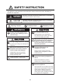
SAFETY INSTRUCTION
Always wear safety goggles and a
dust mask when installing to avoid
personal injury.
WARNING
Indicates a potentially hazardous situation which, if not avoided,
could result in death or serious injury.
CAUTION
Indicates a potentially hazardous situation which, if not avoided,
may result in minor or moderate injury.
Warning, Caution
Mandatory Action
Prohibitive Action
WARNING
CAUTIONCAUTION
GPS position and velocity accuracies
are controlled by the U.S. Department
of Defense. Therefore, the position
accuracy described in the pecifications
cannot be guaranteed.
No one navigation device should ever
be solely relied upon for the
navigation of a vessel.
Always confirm position against all
available aids to navigation, for safety of
vessel and crew.
The compass safe distance for
standard and steering compasses is
0.30 m.
Observe this distance to prevent
inteference to a magnetic compass.
Do not use high-pressure cleaners to
clean this equipment.
This equipment has the waterproof rating
outlined in the specifications, at the back
of this manual. However, the use of
high-pressure cleaning equipment can
cause water ingress, resulting in damage
to, or failure of, the equipment.
Do not disassemble the unit.
Disasembling the unit will damage
the waterproof seal. Further, there are
no user-serviceable parts inside.
The operator of this equipment must read these safety instructions before attempting to
operate the equipment.
CAUTIONCAUTION
The input voltage shall be 12 - 24 VDC.
Any other input voltage can damage the
equipment.
Make power connections to a 12 - 24
VDC power source that is isolated
from the engine start battery(s).
Voltage drop may cause the GPS
receiver to lose information and/or
change operating mode.
A safe installation requires a 0.5 amp
fast-blow fuse or circuit breaker.

iii
TABLE OF CONTENTS
Note: This manual contains both English and Japanese instructions. The Installation
Materials, Outline Drawings, and Interconnection Diagram are located at the back of this
manual.
FOREWORD................................................................................................................... iv
SYSTEM CONFIGURATION ........................................................................................... v
1. INSTALLATION ........................................................................................................ 1
1.1 Equipment Lists.............................................................................................................1
1.2 Tools & Materials...........................................................................................................1
1.3 Choosing the Mounting Location...................................................................................2
1.4 Mounting........................................................................................................................3
1.4.1 Pole/Rail (Pipe) Mount ...........................................................................................3
1.4.2 Deck Mount............................................................................................................4
1.4.3 Flush Mount ...........................................................................................................5
2. WIRING, SETTINGS ................................................................................................. 6
2.1 CAN bus Connection (Type A or N) ..............................................................................6
2.1.1 Direct Connection...................................................................................................6
2.1.2 Network Connection...............................................................................................7
2.1.3 Routing and Connecting the Cable Assembly........................................................8
2.2 NMEA 0183 Connection (Type B or N) .........................................................................9
2.3 Settings for NavNet vx2...............................................................................................10
3. MAINTENANCE, TROUBLESHOOTING ............................................................... 11
3.1 Maintenance................................................................................................................11
3.2 Troubleshooting...........................................................................................................11
4. TECHNICAL INFORMATION ................................................................................. 12
4.1 NMEA 0183 Sentences ...............................................................................................12
4.2 NMEA 2000 PGN Commands.....................................................................................13
SPECIFICATION ....................................................................................................... SP-1
INSTALLATION MATERIALS..................................................................................... A-1
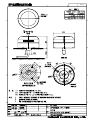
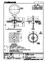
OUTLINE DRAWINGS ................................................................................................ D-1
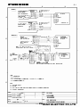
INTERCONNECTION DIAGRAM ................................................................................ S-1

iv
FOREWORD
A Word to the Owner of the GP-330B
Congratulations on your choice of the FURUNO GP-330B GPS Receiver. We are confident you
will see why the FURUNO name has become synonymous with quality and reliability.
Since 1948, FURUNO Electric Company has enjoyed an enviable reputation for quality marine
electronics equipment. This dedication to excellence is furthered by our extensive global network
of agents and dealers.
This equipment is designed and constructed to meet the rigorous demands of the marine environ-
ment. However, no machine can perform its intended function unless installed, operated and
maintained properly. Please carefully read and follow the recommended procedures for installa-
tion and maintenance.
Thank you for considering and purchasing FURUNO equipment.
Feature
The GP-330B is a high performance GPS Receiver designed for any type of vessel. This compact
and cost-effective receiver offers extremely accurate position fixes, within 3 meters with the WAAS
mode activated.
•
65 channels for receiving 12 satellites simultaneously
•
Output in CAN bus or NMEA 0183 format
•
Position fixed within approx. 60 seconds after start up
• Position updated every second
• Spa
ce-saving installation
•
Ideal position-fixing sensor for NavNet 3D series
Program No.
• BOOT:1.***
• App
l:1.***
• GPS:13.*.*
** den
otes minor modifications.
CE declaration
With regards to CE declarations, please refer to our website (www.furuno.com), for further infor-
mation on RoHS conformity declarations.

v
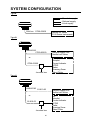
SYSTEM CONFIGURATION
Type A
Type B
Type N
: Standard supply
: Optional supply
: Local supply
NavNet 3D Series
FI-50 Series Instruments
CAN bus
CP20-03200
NMEA0183
CP20-03220
CP20-03220
Remote Display Unit
NavNet vx2 Series
AIS
Autopilot
Current Indicator
ECDIS
Radar
Scanning Sonar
Video Plotter
Junction box
22-910-03
22-910-03
NMEA0183
Remote Display Unit
NavNet vx2 Series
AIS
Autopilot
Current Indicator
ECDIS
Radar
Scanning Sonar
Video Plotter
Junction box
or

1
1. INSTALLATION
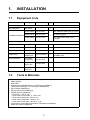
1.1 Equipment Lists
1.2 Tools & Materials
Name Type Code No. Qty Remarks
Standard Supply
GPS Receiver GP-330B 1
Installation Materials
CP20-03200 000-012-581
1
With CAN bus cable (6 m) (A Type)
CP20-03210 000-012-582 No cable (N Type)
CP20-03220 000-037-142 With NMEA0183 cable (10 m)
(B Type)
Optional Supply
Cable Assy. 33-1209-01 001-193-460-10 1 6 m, for CAN bus
Cable Assy. 33-1209-02 001-193-470-10 1 10 m, for CAN bus
Cable Assy. 22-910-03 001-163-140-10 1 10 m, for NMEA 0183
Cable Assy.
MJ-A7SPF/
SRMD-100
000-144-534-11 1
10 m, straight, MJ7P(P)-MJ7P(J),
for NMEA 0183
Flush Mount Kit GP-330B-
FLUSH KIT
001-037-630
1
Deck Mount Kit GP-330B-
DECK KIT
001-037-640
1
Pipe Mount Kit GP-330B-
PIPE KIT
001-041-560 1
• Mounting hardware with standard 1-14" UNS (Pole/Rail Mount installation) threads
• Safety goggles
• Dust mask
• Screwdrivers (Pole/Rail Mount or Deck Mount installation)
• Teflon pipe thread tape, 1/2" wide (some installations)
• Pencil (some installations)
• Electric drill (some installations)
• Drill bits (some installations):
• Pilot hole - 3 mm or 1/8"
• Deck mount screw holes - 5.1 mm or #7
• Deck mount cable hole - 25 mm or 1”
• Flush mount stud holes - 6 mm or 1/4”
• Flush mount cable hole - 38 mm or 1-1/2”
• Loctite 242 or removable thread locker (Flush Mount installation)
• Cable ties (some installations)

1. INSTALLATION
2
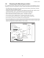
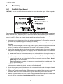
1.3 Choosing the Mounting Location
For a reliable GPS signal, selecting the best location for the receiver is very important. It can be
mounted on a pole, rail, or flat surface. Choose a location that balances the requirements below.
• The GPS receiver must have a clear view of the sky to the horizon in all directions. Note that
frozen water spray may degrade reception.
• Referring to the figure below for distances, mount away from any VHF radio, satellite commu-
nications equipment, radar, or other antennas to avoid mutual interference.
• Mount above or below any radar beam. Do not mount within a radar beam.
• Mount reasonably level with the earth’s surface -- not tilted to one side.
• Do not mount on top of a sailboat mast. The sway will cause jitter in the data.
• Do not mount where the GPS receiver could be a tripping hazard or tread upon.
• Be sure there is access to the underside of the mounting surface.
• Be sure the cable(s) can be routed to reduce electrical interference from other electrical wiring
and any equipment with a strong magnetic field such as radar, radio transmitters, engines, gen-
erators, etc. Separate the cables by at least 1 meter (3 feet).
not within
INMARSAT beam
VHF antenna
or RX MF/HF
whip antenna
Loop
antenna
GPS receiver
TX whip
antenna
(MF/HF)
INMARSAT
antenna
Long-wire
TX MF/HF
antenna
Min. 3 m
not within
radar beam
Min. 1 m
Min. 4 m
Min. 1 m
Min. 5 m
Min. 1.5 m
Min. 5 m
Radar
Min. 4 m
B-, F-type: 25°
C-type: 15°
Antenna
insulator

1. INSTALLATION
3
1.4 Mounting
1.4.1 Pole/Rail (Pipe) Mount
CAUTION! - Do not use the flush mount materials to mount the unit on a pole. Water may leak
into the unit.
The nut assembly supplied has standard 1-14" UNS threads that can be screwed to a standard
marine antenna mount, extension pole, or rail-mount bracket. Before beginning the installation,
plan for securing the pole/rail bracket to the boat and purchase locally all the necessary hardware.
It may be helpful to fasten the pole/rail bracket to the boat before proceeding.
1. Unscrew the mount base (part C) from the surface bracket (part E). (The surface
bracket is
not used in this installation. See the next page for part (E)).
2. Remove the label from the GPS receiver’s socket (underside of receive
r). The label may be
discarde
d.
Fasten the mount base (part C) to the GPS receiver (part A) with the supplied two panhe
ad
scr
ews, flat washers and spring washers. The torque for the screws is 1.35 N m.
3. Decide if you want the cable to exit through the center or along the side of the pole/rail brac
ket.
Slide the nut assembly (captive nut and adaptor) onto the cable at the 9-pin GPS connector
end. Do n
ot connect the GPS receiver at this time.
1) Center exit: Pass the instrument connector end of the cable down through the center o
f
the pole. Be sure to leave several inches of cable extending beyond the nut assembly.
2) Side exit: Place the cable side-exit adaptor (part D) over the cable. Being sure th
e cable
is passing thro
ugh the slot in the side, screw the nut assembly onto the adaptor. Hand-
tighten only. Do not over tighten.
Note: Use the adaptor supplied as it has smooth edges that will not chafe the cable.
Do
not use a purchased part.
CAUTION: if you use a thread locker, use teflon pipe thread tape. Do not use a liquid thread
locker as it may weaken the plastic, causing it to swell and crack.
4. Screw the extension pole/rail bracket onto the nut assembly/cable side-exit adaptor. Hand-
tighten only. Do not over tighten.
5. Remove the protective cap from the GPS connector on the cable. (Save the
cap to protect the
conn
ector, when the receiver is removed.) Plug the cable firmly into the GPS receiver.
6. With the alignment tab on the GPS receiver facing forward, slide the captive nut upward
and
scr
ew it onto the mount base. Hand-tighten only. Do not over tighten.
1)
2)

1. INSTALLATION
4
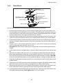
1.4.2 Deck Mount
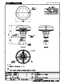
See the outline drawing for mounting hole dimensions and fixing instructions
1. Unscrew the mount base (part C) from the surface bracket (part E) (see figure above). Re-
move the label from over the GPS receiver's socket. (The label may be discarded.) Fasten the
mount base (part C) to the GPS receiver (part A) with the supplied panhead screws, flat wash-
ers and spring washers. The torque for the screws is 1.35 N m.
2. Screw the surface bracket (part E) onto the mount base of the assembled GPS receiver. Use
a pencil to extend the alignment tab onto the surface bracket. Unscrew the surface bracket.
3. At the selected location, position the surface bracket with the pencil mark facing forward. Us-
ing it as a template, mark the position for the three mounting screws and the center hole for
the cable.
4. Using a 3 mm or 1/8" bit, drill the pilot holes. Using 5.1 mm or #7 bit, drill the three mounting
holes. Drill the cable hole with a 25 mm or 1" bit.
Fiberglass-Minimize surface cracking by running the drill in reverse until the gelcoat is pen-
etrated.
5. At the location shown in the figure above, coat the surface bracket (part E) with silicone seal-
ant.
6. Apply silicone sealant to the three #10 x 1/2" self-tapping screws to seal the deck. With the
pencil mark facing forward, fasten the surface bracket in place. Do not block the drain slots.
They will allow any water that accumulates inside the surface bracket to escape. CAUTION:
Do not use a liquid thread locker as it may weaken the plastic, causing it to swell and crack.
7. Wrap pipe thread tape around the threads of the mount base two times to seal it tightly to the
surface bracket.
8. Coat the part of the GPS connector shown in the figure on page 4 with silicone sealant. Pass
the GPS connector end of the cable up through the hole in the surface bracket.
9. Remove the protective cap from the cable's GPS connector. (Save the cap to protect the con-
nector, when the receiver is removed.) Plug the cable firmly into the GPS receiver.
10. Counterclockwise twist the cable three and one-half turns. Then screw the GPS receiver onto
the installed surface bracket. Hand-tighten only. Do not over tighten.
Aligment tab
GPS receiver (part A)
Mount base (part C)
Panhead screw (2 pcs.)
GPS connector
Self-tapping screw (3 pcs.)
#10x1/2"
Surface bracket (part E)
Silicone sealant
Silicone sealant
Flat washer (2 pcs.)
Spring washer (2 pcs.)
Drain slot (6)

1. INSTALLATION
5
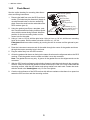
1.4.3 Flush Mount
See the outline drawing for mounting hole dimen-
sions and fixing instructions.
1. Remove the label from over t
he GPS receiver's
socket.
(The label may be discarded.) Apply re-
movable thread locker to the two studs sup-
plied. Screw the studs into the underside of
the
GPS receiver (part
A).
2. Using the gasket (part B) as a template, posi-
tion it at the selected mounting location up
side
down with
the arrow facing forward
. Mark the
position
for the two mounting holes an
d the
cent
er hole for the cable.
3. Using a 3 mm or 1/8" bit, drill the pilot holes. Using a 6 mm or 1/4" bit, drill the two mounting
holes for the studs. Drill the cable hole with a 38 mm or 1-1/2" bit.
Fiberglass-Minimize surface cracking by running the drill in reverse until the gelcoat is pen-
etrated.
4. Pass the instrument connector-end of the cable through the center of the gasket and
down
through
the center mounting hole in the boat.
5. Plug the cable firmly into the GPS receiver.
6. Orient the gasket with the arrow facing in the same direction as the alignment tab on th
e GPS
receiver.
Push the gasket onto the studs and slide it over the connecto
r.
Note: Th
e gasket fits one way only. A groove in the gasket fits over the alignment tab on
the
conn
ector.
7. With the GPS receiver alignment tab pointing forward, push the studs through the moun
ting
surfa
ce. Check to be sure the gasket is tucked under the lip of the unit. From underneath t
he
moun
ting surface, slide the flat washer and spring washer onto each stud. Fasten
the studs
with the
thumb nuts. Hand-tighten only. Do not over tighten.
8. Coat the circumference of the GPS receiver with silicone sealant so that there is no space be-
tween the GPS receiver and the mounting surface.
GPS receiver (part A)
Aligment tab
Stud (2 pcs.)
GPS connector
Gasket (part B)
Arrow
Mounting surface
Thumb nut (2 pcs.)
Flat washer (2 pcs.)
Spring washer (2 pcs.)

6
2. WIRING, SETTINGS
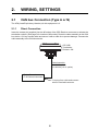
2.1 CAN bus Connection (Type A or N)
The LEN (Load Equivalency Number) for this equipment is 2.
2.1.1 Direct Connection
Insert the contact pin (supplied) into the #5 socket of the GPS Receiver connector to activate the
termination resistor. (See page 8 for location of #5 socket.) Route the cable assembly to the CAN
bus device. Coil any excess cable and secure it with a cable tie to prevent damage. Connect the
cable assembly to the CAN bus device.
Cable Assembly
33-1209-01 (6 m)
33-1209-02 (10 m, option)
GP-330B
Termination
Resistor: ON
* Cut plug from cable and connect
wires to terminal/connector
.
- Radar Sensor*
- FI-50 Series Instrument

2. WIRING, SETTINGS
7
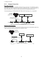
2.1.2 Network Connection
Drop cable connection
A drop cable is connected to a backbone cable with T-type connectors*. The backbone cable is
of the "light" type. Attach a terminator at the ends of the backbone cable. Only two termination re-
sistors are required on an CAN bus network. More than two will degrade performance.
* Recommended
type: LTWSS-050505-FMF-TS001 (LTW Technology, Inc.), or equivalent
Backbone cable connection
Use this connection method to connect the GP-330B at the final node in the backbone cable. Use
T-type connectors to connect equipment to the backbone cable.
Backbone cable
Terminator 1
T-connector
T-connector
- NavNet 3D Series
- FI-50 Instrument
Cable Assembly
33-1209-01 (6 m)
Power
(12 -24 VDC)
T-connector
Power
(12 - 24 VDC)
GP-330B
Termination
Resistor: OFF
Terminator 2
GP-330B
Termination
Resistor: ON
T-connector
Cable Assembly
33-1209-01 (6 m)
33-1209-02 (10 m, option)
Power
(12 - 24 VDC)
T-connector
- NavNet 3D Series
- FI-50 Instrument
Power
(12 - 24 VDC)
T
-connector
Backbone cable (max. 25 m)

2. WIRING, SETTINGS
8
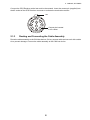
Connect the GPS Receiver at the last node in the network. Insert the contact pin (supplied) into
the #5 socket of the GPS Receiver connector to activate the termination resistor.
2.1.3 Routing and Connecting the Cable Assembly
Route the cable assembly to the CAN bus device. Coil any excess cable and secure it with a cable
tie to prevent damage. Connect the cable assembly to the CAN bus device.
Contact pin inserted
in #5 socket
Ta b

2. WIRING, SETTINGS
9
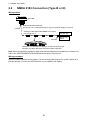
2.2 NMEA 0183 Connection (Type B or N)
Wiring outline
Note: When connecting to equipment other than a Remote Display Unit or NAVnet vx2 series unit,
refer to the INTERCONNECTION DIAGRAM at the back of this manual.
Wiring procedure
Route the cable assembly to the display. Coil any excess cable and secure it with a cable tie to
prevent damage. Connect the GPS Receiver to your NMEA 0183 display.
NAVnet vx2
Series
Waterproof connectors by wrapping them with vulcanizing tape
and then vinyl tape. Bind tape ends with suitable cable ties.
GP-330B
Female
NMEA 0183 Cable Assembly
(22-910-03, 10 m, Standard supply for Type B, Optional supply for Type N)
Remote Display
Unit (RD-30)
Extension cable (MJ-A7SPF/SRMD-100, option)
max. length: 50 m
Female

2. WIRING, SETTINGS
10
2.3 Settings for NavNet vx2
The following items in the NavNet vx2 menu system are applicable to the GP-330B. For details
and operating procedure, see the Installation Manual for your NavNet vx2 model.
NAV SETUP menu
Set POSITION SOURCE to GPS or ALL.
GPS SETUP menu
• GEODETIC DATUM
Select your chart type. WGS-84 is the GPS standard.
• FIX
MODE
Set position fixing mode to 2D/3D (three or four satellites in view).
• COLD START
Clear the Almanac currently stored in the GPS receiver to receive the latest Almanac.
WAAS SETUP menu
• WAAS MODE
Select ON to use the WAAS mode.
• WAAS
SEARCH
Set WAAS satellite search method to automatic.
• CORRECTIONS DATA
Select the type of message for WAAS connection, 00 for North America, 02 elsewhere.
WAAS settings effective from the version numbers shown below.
C-MAP specification NAVIO specification
Program No. Model Program No. Model
1950026-03.02 Model 1804C-BB 1950025-03.02 Model 1804C-BB
1950024-03.02 Model 1804C 1950023-03.02 Model 1804C
1950028-03.02 Model 1704C 1950027-03.02 Model 1704C

11
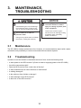
3. MAINTENANCE,
TROUBLESHOOTING
3.1 Maintenance
The GP-330B is virtually maintenance free. However, it is recommended to wipe it with a water-
moistened cloth periodically to remove accumulated dirt and water deposits.
3.2 Troubleshooting
If position is not found within a reasonable amount of time, check the following items.
• Is there power to the GPS receiver? (Check unit that is supplying power to the GP-330B.)
• Are all the connections tight?
• Does the GPS receiver have a clear view of the sky?
• Is there interference from other antennas or instruments?
• Is cabling damaged?
• Is the cable-run free of kinks or damage?
• Is there damage to the GPS receiver?
• Is there ice on the GPS receiver?
CAUTIONCAUTION
Do not disassemble the unit.
Disassembling the unit will damage
the waterproof seal. Further, there
are no user-serviceable parts inside.
Do not immerse in water or
pressure wash.
Doing so may allow water to infiltrate
the sensor, voiding the warranty.
Do not apply paint, anti-
corrosive sealant or contact
spray to coating or plastic parts
of the equipment.
Those items contain organic
solvents that can damage coating
and plastic parts, especially
plastic connectors.
NOTICE

12
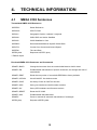
4. TECHNICAL INFORMATION
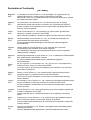
4.1 NMEA 0183 Sentences
Transmitted NMEA 0183 Sentences
* Default outp
ut
Received NMEA 0183 Sentences and Commands
$GPDTM* Datum Reference
$GPGGA* GPS Fix Data
$GPGLL* Geographic Position -Latitude / Longitude
$GPGSA GNSS DOP and Active Satellites
$GPGSV GNSS Satellites in View
$GPRMC* Recommended Minimum Specific GNSS Data
$GPVTG* Course Over Ground and Ground Speed
$GPZDA* Time and Date
$PFEC,pidat Response to $PFEC,pireq
$PAMTC,BAUD Change the baud rate from the nominal 4800 baud to 38400 baud
$PAMTC,EN Enable/disable transmission of specific sentences, and change their rate of
transmission
$PAMTC,ERST Reset the user portion of nonvolatile EEPROM to factory defaults
$PAMTC,OPTION WAAS ON/OFF. Set 3d/Auto mode.
$PAMTC,POST Set Query Power On Self Test function
$PAMTC,QPS Query part number and serial number versions
$PAMTC,QV Query GPS hardware and firmware versions
$PAMTC,RESET Reset the GP-330B
$PAMTC,SIM Enable/disable Simulate Mode
$PAMTX Pause or resume all automatic transmission of messages
$PFEC,pireq Request to $PFEC,pidat

4. TECHNICAL INFORMATION
13
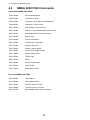
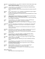
4.2 NMEA 2000 PGN Commands
Transmitted NMEA 2000 PGNs
Received NMEA 2000 PGNs
PGN 059392 ISO Acknowledgment
PGN 060928 ISO Address Claim
PGN 065285 Proprietary: Boot State Acknowledgment
PGN 065287 Proprietary: Access Level
PGN 126208 Acknowledge Group Function
PGN 126464 PGN List - Transmit/Received PGN's Group
PGN 126720 Addressable Multi-Frame Proprietary
PGN 126992 System Time
PGN 126996 Product Information
PGN 126998 Configuration Information
PGN 127258 Magnetic Variation
PGN 129025 Position, Rapid Update
PGN 129026 COG & SOG, Rapid Update
PGN 129029 GNSS Position Data
PGN 129033 Time & Date
PGN 129044 Datum
PGN 129538 GNSS Control Status
PGN 129539 GNSS DOPs
PGN 129540 GNSS Sats in View
PGN 059904 ISO Request
PGN 060928 ISO Address Claim
PGN 126208 Request Group Function
PGN 126208 Command Group Function
PGN 126720 Addressable Multi-Frame Proprietary
Pagina se încarcă...
Pagina se încarcă...
Pagina se încarcă...
Pagina se încarcă...
Pagina se încarcă...
Pagina se încarcă...
Pagina se încarcă...
Pagina se încarcă...
Pagina se încarcă...
Pagina se încarcă...
Pagina se încarcă...
Pagina se încarcă...
Pagina se încarcă...
-
 1
1
-
 2
2
-
 3
3
-
 4
4
-
 5
5
-
 6
6
-
 7
7
-
 8
8
-
 9
9
-
 10
10
-
 11
11
-
 12
12
-
 13
13
-
 14
14
-
 15
15
-
 16
16
-
 17
17
-
 18
18
-
 19
19
-
 20
20
-
 21
21
-
 22
22
-
 23
23
-
 24
24
-
 25
25
-
 26
26
-
 27
27
-
 28
28
-
 29
29
-
 30
30
-
 31
31
-
 32
32
-
 33
33


în alte limbi
- English: Furuno GP330B User manual
Lucrări înrudite
Alte documente
-
Garmin ECHOMAP UHD 75sv Manualul proprietarului
-
Vaisala MOG100 Manual de utilizare
-
Navitel E707 Magnetic Manual de utilizare
-
Garmin GPSMAP® 86s Manualul proprietarului
-
Garmin Montana® 750i Manualul proprietarului
-
Garmin GPSMAP® 66i Manualul proprietarului
-
Garmin GPSMAP® 66s Manualul proprietarului
-
-
Garmin GPSMAP® 64x Manual de utilizare
-
Garmin GPSMAP® 86sci Manual de utilizare