Pagina se încarcă...
Pagina se încarcă...

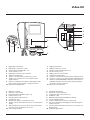
Video Kit
3
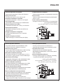
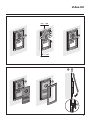
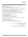
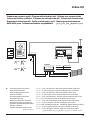
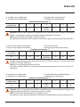
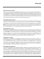
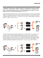
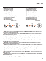
• Vecchio impianto a campanello
Impianato esistente con 3 fili e sola chiamata.
• Old system with bell
Existing system with 3 wires and just call.
• Ancienne installation a sonnette
Installation existante à 3 fils et un seul appel.
• Alte klingelanlage
Vorhandene 3-Leiter Anlage nur mit Ruffunktion.
• Vieja instalación con timbre
Instalación existente con 3 hilos y una llamada.
• Oude deurbelinstallatie
Bestaande 3-aderige installatie met alleen een
oproepfunctie.
• Antiga instalação em campaínha
Instalação existente com 3 fios e somente
chamada.
• Παλαιό σύστηα ε κουδούνι
Παρόν σύστηα ε 3 καλώδια και ια κλήση
• Старая система со звонком
3 .
• Esk zl sstem
3 kablo ve sadece arama le donatılmış halhazırda
mevcut sstem.
• Stara instalacja z dzwonkiem
Istniejąca instalacja dzwonkowa na 3 przewodach.
}
346000
0322 06
IP30
PRI 230V~ 50 - 60Hz 260mA
BUS
2-1
27V 1,2A
PRI
230 Vac
PS
BUS TK
BUS PI
346830
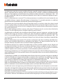
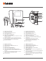
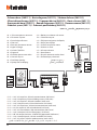
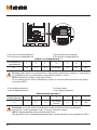
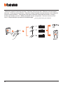
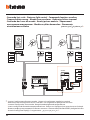
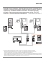
• Nuovo impianto citofonico
Impianto realizzato senza modifiche ai 2 fili
esistenti: chiamata, citofono e serratura.
• New door entry system
System made without modifications to the 2 existing
wires; call, door entry and electric door lock.
• Nouvelle installation phonique
Installation réalisée sans modifications sur les 2
fils existants: appel, phone, et serrure électrique.
• Neue haustelefonanlage
Anlage ohne Änderungen an den vorhandenen 2 Leiter:
Ruffunktion, haustelefon und elektrischer Schloss.
• Nueva instalación interfónica
Instalación realizada sin las modificaciones a los 2 hilos
existentes: llamada, interfono y cerradura eléctrica.
• Nieuwe deurtelefooninstallatie
Installatie aangelegd zonder wijzigingen aan de 2 bestaande
aders: oproep, deurtelefoon en elektrisch deurslot.
• Nova instalação do intercomunicador
Instalação realizada sem modificar os 2 fios existentes:
chamada, intercomunicador e fechadura eléctrica.
• Νέο σύστηα ενδοεπικοινωνία
Κατασκευή συστήατο χωρί ετατροπέ στα 2
υπάρχοντα καλώδια: κλήση, ενδοεπικοινωνία και κλειδαριά.
•
Новая домофонная система
, 2
: , .
• Yeni dahili ünite sistemi
Halihazırda mevcut 2 kabloda değişiklik
yapılmadan gerçekleştirilmiş sistem: Arama, dahili
ünite ve kilitleme.
• Nowa instalacja domofonowa
Instalacja wykorzystująca 2 istniejące przewody
– wywołanie, domofon, otwarcie drzwi.
•
•
230 Vac 12 V
Pagina se încarcă...
Pagina se încarcă...
Pagina se încarcă...
Pagina se încarcă...
Pagina se încarcă...
Pagina se încarcă...
Pagina se încarcă...
Pagina se încarcă...
Pagina se încarcă...
Pagina se încarcă...

14
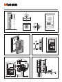
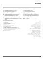
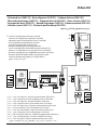
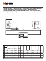
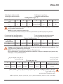
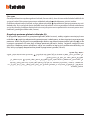
• Schema base (369111) • Basic diagram (369111) • Schéma de base (369111)
• Übersichtszeichnung (369111) • Esquema básico (369111) • Basis schema (369111)
• Esquema de base (369111) • Βασικό διάγραα (369111) • (369111)
• Standart şema (369111) • Schemat podstawowy (369111)
• S+ S- = 18 V; 4 A impulsivi; 250 mA mantenimento (30 max)
• S+ S- = 18 V; 4 A impulsive; 250 mA holding current (30 max)
• S+ S- = 18 V; 4 A impulsifs; 250 mA entretien (30 max)
• S+ S- = 18 V; 4 A impulsstrom; 250 mA Haltestrom (30 max)
• S+ S- = 18 V; 4 A impulsivos; 250 mA mantenimiento (30 max)
• S+S- = 18 V; 4 A impulsief; 250 mA onderhoud (30 max)
• S+ S- = 18 V; 4 A instantâneos; 250 mA continuos (30 max)
• S+ S- = 18 V; 4 A παλικά; 250 mA διατήρηση (30 max)
• S+S- = 18 - 4A – 250 (30 .)
• S+ S- = 18 V; 4 A empülsyonlu; 250 mA muhafaza (30 max)
• S+ S- = 18 V; 4 A impuls; 250 mA podtrzymanie (maks. 30 )
= -S+S •
•
• A = Pulsante apertura serratura
B = Chiamata al piano
• A = Door lock pushbutton
B = Floor call
• A = Poussoir d’ouverture serrure
B = Appel à l’étage
• A = Schalter Türöffner
B = Etagenruf
• A = Pulsador apertura cerradura
B = Llamada al piso
• A = Drukknop opening
B = Oproep aan verdieping
• A = Botão para abertura do trinco
B = Chamada ao piso
• A = Πλήκτρο ανοίγατο κλειδαριά
B = Κλήση στον όροφο
• A =
B =
• A = kilit açma butonu
B = Katta arama
• A = Przycisk otwarcia zamka drzwi
B = Dzwonek przy drzwiach
5
BUS
1
ET
2 1
ON
OFF
PS
BUS TK
BUS PI
346830
BUS
PL S+
S-
A
BUS 2 1
230 Vac
3
2
1
O
IP30
PRI
PRI 230 V~ 50 - 60 Hz 260 mA
346000
}
BUS
2 - 1
27V 1,2A
CEBEC
N
N
F
B
P
= –
= –
N
= –
= –
T = –
S = –
N
= –
= –
P
= –
= –
MOD = –

Video Kit
15
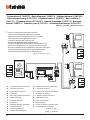
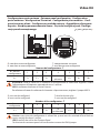
• Schema base (369121) • Basic diagram (369121) • Schéma de base (369121)
• Übersichtszeichnung (369121) • Esquema básico (369121) • Basis schema (369121)
• Esquema de base (369121) • Βασικό διάγραα (369121) • (369121)
• Standart şema (369121) • Schemat podstawowy (369121)
*
• Inserire il configuratore fornito a corredo
• Connect the configurator supplied as standard
•
Mettre en place le configurateur fourni à cet effet
• Den mitgelieferten Konfigurator einsetzen
• Inserte el configurador suministrado
• Breng de standaard geleverde configurator aan
• Inserir o configurador fornecido no equipamento base
• Εισάγετε τον διαορφωτή που χορηγείται στον εξοπλισό
• ,
• Donanım dahlnde tedark edlmş konfgüratörü takın
• Umieścić konfigurator będący na wyposażeniu
• S+ S- = 18 V; 4 A impulsivi; 250 mA mantenimento (30 max)
• S+ S- = 18 V; 4 A impulsive; 250 mA holding current (30 max)
• S+ S- = 18 V; 4 A impulsifs; 250 mA entretien (30 max)
• S+ S- = 18 V; 4 A impulsstrom; 250 mA Haltestrom (30 max)
• S+ S- = 18 V; 4 A impulsivos; 250 mA mantenimiento (30 max)
• S+S- = 18 V; 4 A impulsief; 250 mA onderhoud (30 max)
• S+ S- = 18 V; 4 A instantâneos; 250 mA continuos (30 max)
• S+ S- = 18 V; 4 A παλικά; 250 mA διατήρηση (30 max)
• S+S- = 18 - 4A – 250 (30 .)
• S+ S- = 18 V; 4 A empülsyonlu; 250 mA muhafaza (30 max)
• S+ S- = 18 V; 4 A impuls; 250 mA podtrzymanie (maks. 30 )
= -S+S •
ON
OFF
ON
OFF
PS
BUS TK
BUS PI
346830
BUS
PL S+
S-
A
BUS 2 1
230 Vac
5
BUS
1
ET
2 1
3
2
1
O
5
BUS
1
ET
2 1
3
2
1
O
IP30
PRI
PRI 230 V~ 50 - 60 Hz 260 mA
346000
}
BUS
2 - 1
27V 1,2A
CEBEC
N
N
F
B
B
N
= –
= *1
P
= –
= –
MOD = –
N
= –
= –
P
= –
= –
MOD = –
P
= –
= –
N
= –
= –
T = –
S = –

16
* • Inserire il configuratore fornito a corredo
• Connect the configurator supplied as standard
•
Mettre en place le configurateur fourni à cet effet
• Den mitgelieferten Konfigurator einsetzen
• Inserte el configurador suministrado
• Breng de standaard geleverde configurator aan
• Inserir o configurador fornecido no equipamento base
• Εισάγετε τον διαορφωτή που χορηγείται στον εξοπλισό
• ,
• Donanım dahlnde tedark edlmş konfgüratörü takın
• Umieścić konfigurator będący na wyposażeniu
P
= –
= –
N
= –
= –
T = –
S = –
5
BUS
1
ET
2 1
B
ON
OFF
3
2
1
O
PS
BUS TK
BUS PI
346830
BUS
PL S+
S-
A
BUS 2 1
230 Vac
5
BUS
1
ET
2 1
IP30
PRI
PRI 230 V~ 50 - 60 Hz 260 mA
346000
}
BUS
2 - 1
27V 1,2A
CEBEC
N
N
F
B
ON
OFF
3
2
1
O
N
= –
= *1
P
= –
= –
MOD = –
N
= –
= –
P
= –
= –
MOD = –
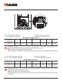
• A = Pulsante apertura serratura
B = Chiamata al piano
• A = Door lock pushbutton
B = Floor call
• A = Poussoir d’ouverture serrure
B = Appel à l’étage
• A = Schalter Türöffner
B = Etagenruf
• A = Pulsador apertura cerradura
B = Llamada al piso
• A = Drukknop opening
B = Oproep aan verdieping
•
• A = Botão para abertura do trinco
B = Chamada ao piso
• A = Πλήκτρο ανοίγατο κλειδαριά
B = Κλήση στον όροφο
• A =
B =
• A = kilit açma butonu
B = Katta arama
• A = Przycisk otwarcia zamka drzwi
B = Dzwonek przy drzwiach
• Schema base 2 (369121) • Basic diagram 2 (369121) • Schéma de base 2 (369121)
• Übersichtszeichnung 2 (369121) • Esquema básico 2 (369121) • Basis schema 2
(369121) • Esquema de base 2 (369121) • Βασικό διάγραα 2 (369121) •
2 (369121) • Standart şema 2 (369121) • Schemat podstawowy 2 (369121)

Video Kit
17
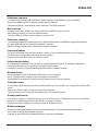
• Schema con serratura a relè • Diagram with relay door lock • Schéma avec serrure à relais
• Schema mit Schloss und Relais • Esquema con cerradura de relé • Schema met slot met relais
• Esquema do trinco com relè • Σχέδιο ε κλειδαριά ε ρελέ •
• Rölel kltl şema • Schemat ze zamkiem na przekaźnik
·
•
A= • Pulsante apertura serratura
• Door lock pushbutton
• Poussoir d’ouverture serrure
• Schalter Türöffner
• Pulsador apertura cerradura
• Drukknop opening
• Botão para abertura do trinco
• Πλήκτρο ανοίγατο κλειδαριά
•
• kilit açma butonu
• Przycisk otwarcia zamka drzwi
• S+ S- = 18 V; 4 A impulsivi; 250 mA mantenimento (30 max)
• S+ S- = 18 V; 4 A impulsive; 250 mA holding current (30 max)
• S+ S- = 18 V; 4 A impulsifs; 250 mA entretien (30 max)
• S+ S- = 18 V; 4 A impulsstrom; 250 mA Haltestrom (30 max)
• S+ S- = 18 V; 4 A impulsivos; 250 mA mantenimiento (30 max)
• S+S- = 18 V; 4 A impulsief; 250 mA onderhoud (30 max)
• S+ S- = 18 V; 4 A instantâneos; 250 mA continuos (30 max)
• S+ S- = 18 V; 4 A παλικά; 250 mA διατήρηση (30 max)
• S+S- = 18 - 4A – 250 (30 .)
• S+ S- = 18 V; 4 A empülsyonlu; 250 mA muhafaza (30 max)
• S+ S- = 18 V; 4 A impuls; 250 mA podtrzymanie (maks. 30 )
= -S+S •
PS
BUS TK
BUS PI
346830
8 A cosφ = 1
4 A cosφ = 0,7
3 A cosφ = 0,4
24 Vdc; 24 Vac
24 Vac
24 Vac
NO
NC
C
346250
S-
S+
C
NC
NO
BUS
PL S+
S-
A
BUS 2 1
230 Vac
IP30
PRI
PRI 230 V~ 50 - 60 Hz 260 mA
346000
}
BUS
2 - 1
27V 1,2A
CEBEC
N
N
F
JMP 3
JMP 4
JMP 1
JMP 2
P
= –
= –
N
= –
= –
T = –
S = –
Pagina se încarcă...

Video Kit
19
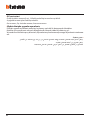
•
Configurazione posto esterno
•
Entrance panel configuration
•
Configuration
poste extérieur
•
Konfiguration Türstation
•
Configuración placa exterior
•
Confi-
guratie externe plaats
•
Configuração unidade externa
•
ιαρρύθιση εξωτερικού
σηείου
•
•
Dış ünte konfgürasyonu
•
Konfigu-
racja panelu zewnętrznego
•
T: temporizzatore serratura
S: non deve essere configurato
• P: non deve essere configurato
N: non deve essere configurato
Numero del configuratore - T
0 = nessun
configuratore
1 2 3 4 5 6 7
4 s 1 s 2 s 3 s
come
pulsante
6 s 8 s 10 s
Attenzione: tutte le volte che si modifica la configurazione è necessario togliere e ridare
l’alimentazione all’impianto, attendendo circa 1 minuto.
JMP4: conferma chiamata su Posto Esterno.
Per eliminare il tono di conferma di chiamata sul posto esterno, togliere il jumper JMP 4.
Number of the configurator - T
0 = no
configurator
1 2 3 4 5 6 7
4 s 1 s 2 s 3 s
as
pushbutton
6 s 8 s 10 s
T: door lock timer relay
S: must not be configured
• P: must not be configured
N: must not be configured
Caution: every time the configuration is altered the system must be switched off and back on
again, waiting for about 1 minute.
JMP4: confirm the call on the Entrance Panel.
To eliminate the entrance panel call confirmation remove the JPM 4 jumper.
BUS
PL
S+ S−
PJ3 J1
J4 J2
T S
N
BUS
PL
S+ S−
PJ3 J1
J4 J2
T S
N
Pagina se încarcă...
Pagina se încarcă...
Pagina se încarcă...
Pagina se încarcă...
Pagina se încarcă...
Pagina se încarcă...
Pagina se încarcă...
Pagina se încarcă...
Pagina se încarcă...
Pagina se încarcă...
Pagina se încarcă...

Video Kit
31
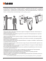
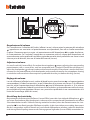
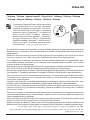
• Si ricorda che la presenza di metallo e rumore di fondo generato da apparecchiature elettriche/
elettroniche (es. computer), può compromettere la qualità e le perfomace del dispositivo di ac-
coppiamento.
• Remember that the presence of metal and background noise generated by electric/electronic equip-
ment (e.g. computers), can affect the quality and the performance of the coupling device.
• Il est rappelé que la présence de métal et de bruit de fond généré par des appareillages élec-
triques/électroniques (ordinateurs par exemple) peut compromettre la qualité et les perfor-
mances du dispositif de couplage.
• Bitte beachten Sie, dass Metallgegenstände und Hintergrundgeräusche elektrischer/elektronischer Geräte
(z.B. PC), die Qualität und Leistung der Kopplungsvorrichtung beeinträchtigen können.
• Recuerde que la presencia de metal y ruido de fondo generado por aparatos eléctricos/electrónicos
(por ejemplo, PC) puede comprometer la calidad y la eficiencia del dispositivo de acoplamiento.
• Men herinnert eraan dat de aanwezigheid van metaal en achtergrondruis gegenereerd door elektri-
sche/elektronische apparatuur (vb. computer) de kwaliteit en de performance van de koppelingsin-
richting kan compromitteren.
•. Lembra-se que o metal e rumor de fundo gerado por aparelhagens eléctricas/electrónicas (ex. com-
putador), pode comprometer a qualidade e a performance do dispositivo de acoplamento.
• Υπενθυίζεται ότι η παρουσία ετάλλων και θορύβου βάθου που δηιουργείται από ηλεκτρικέ/ ηλε-
κτρονικέ συσκευέ (π.χ. ηλεκτρονικό υπολογιστή), πορεί να εταβάλει την ποιότητα και τι επιδόσει
τη συσκευή ζεύξη.
• , , /-
(., ), -
.
• Metal mevcudyet ve elektrk/elektronk chazların (örneğn blgsayar) oluşturduğu fon gürültüsünün
eşleştrme chazının kalte ve performansını etkleyebleceğ hatırlatılır.
• Należy pamiętać, że obecność metalu oraz szum tłowy generowany przez urządzenia elektryczne/
elektroniczne (np. komputer) mogą obniżyć wydajność/jakość działania urządzenia połączonego.
• Commutare l’apparecchio acustico in posizione
T • Switch hearing device in T position • Commuter
l’appareil acoustique sur la position • Das akusti-
sche Gerät auf Position T umschalten • Conmute el
aparato acústico a la posición T • Het akoestisch
toestel naar de stand T schakelen • Comutar o
aparelho acústico para a posição T • Μεταγάγετε
την ηχητική συσκευή στη θέση T •
• Akustk chazı T
pozsyonuna çevrn • Przełączyć aparat akustycz-
ny na pozycję T •
• Teleloop • Teleloop • Appareil auditif • Ringschleife • Teleloop • Teleloop • Teleloop
• Teleloop • Модуль Teleloop • Teleloop • Teleloop • Teleloop

32
10s
BIP
Led OFF Led OFF
10s
BIP
Led OFF
3
2
3
2
1
O
3
2
1
O
1
3501/2
2
0
3501/0
MO DP
N
2 0
• Funzione “Studio professionale” attiva • “Professional studio” function active •
Fonction “Bureau professionnel” activée • Funktion “Professionelles Studio” aktiv •
Función “Oficina Profesional” activada • Kantoorfunctie actief • Função “Escritório
profissional” activa • Λειτουργία “Επαγγελατικό στούντιο” ενεργή •
“ ” • “Mesleki büro” fonksiyonu etkin •
Funkcja “Pracownia” aktywna •
• Per rendere operativa la funzione “Studio Professionale” configurare MOD = 20
• To make the “Professional Studio” function operative, configure MOD = 20
• Pour rendre la fonction “Bureau Professionnel” opérationnelle, configurer MOD = 20
• Um die Funktion “Professionelles Studio” benutzen zu können, folgendermaßen konfigurieren: MOD = 20
• Para activar la función “Estudio Profesional” configure MOD = 20
• Om de functie “kantoorfunctie” operatief te maken MOD = 20 configureren
• Para fazer com que a função “Departamento Profissional” fique operativa configurar MOD = 20
• Για να κάνετε ενεργή τη λειτουργία “Επαγγελατικό Στούντιο” ρυθίστε MOD = 20
• “ ” MOD = 20
• “Mesleki Büro” fonksiyonunu etkin kılmak için MOD = 20 konfigüre edin
• Aby uaktywnić funkcję „Pracownia”, skonfigurować MOD = 20
•

Video Kit
33
10s
BIP
Led OFF Led OFF
10s
BIP
Led OFF
3
2
3
2
1
O
3
2
1
O
1
• Per attivare la funzione
• To activate the function
• Pour activer la fonction
• Zum Aktivieren der Funktion
• Para activar la función
• Om de functie te activeren
• Para activar a função
• Για ενεργοποίηση τη λειτουργία
•
• İşlev etkn kılmak çn
• Aby aktywować funkcję
•
10s
BIP
Led OFF Led OFF
10s
BIP
Led OFF
3
2
3
2
1
O
3
2
1
O
1
• Per disattivare la funzione
• To deactivate the function
• Pour désactiver la fonction
• Zum Deaktivieren der Funktion
• Para desactivar la función
• Om de functie te deactiveren
• Para desactivar a função
• Για απενεργοποίηση τη λειτουργία
•
• İşlev devreden çıkarmak çn
• Aby dezaktywować funkcję
•
• Nota: L’attivazione/disattivazione della funzione “Studio professionale” causa l’apertura della
serratura del posto esterno associato.
• Note: The activation/deactivation of the “Professional studio” function causes the opening of the
associated entrance panel door lock.
• Remarque: L’activation/désactivation de la fonction «Bureau professionnel» provoque l’ouver-
ture de la serrure du poste extérieur associé
• Anmerkung: Bei der Aktivierung/Deaktivierung der Funktion “Professionelles Studio” öffnet sich
das Schloss an der jeweiligen Türstation.
• Nota: La activación/desactivación de la función "Oficina Profesional" causa la apertura de la
cerradura del puesto exterior asociado.
• Opmerking: Het activeren/deactiveren van de kantoorfunctie veroorzaakt de opening van het
deurslot van het bijbehorende deurstation.
• Nota: A activação/desactivação da função "Escritório profissional" causa a abertura da unidade
externa associada.
• Σηείωση: Η ενεργοποίηση/απενεργοποίηση τη λειτουργία “Επαγγελατικό γραφείο” προκαλεί
το άνοιγα τη κλειδαριά τη συνδεδεένη εξωτερική θέση.
• Примечание: / “Профессиональная студия”
.
• Not: Eşleştrlmş dış üntenn kldnn açılması sebeb “Meslek büro” şlevnn etknleştrlmes/dev-
reden çıkarılması.
• Uwaga: Aktywacja /dezaktywacja funkcji “Pracownia” powoduje otwarcie zamka połączonego
panelu zewnętrznego.

34
• Comando luci scale • Staircase light control • Commande lumières escaliers
• Treppenlichtsteuerung • Mando luces escaleras • Bediening lichten trapzaal
• Comando das luzes da escada • Εντολή φώτων σκαλών •
• Merdiven ışıkları kumandası • Sterowanie
oświetleniem na klatce •
*
• Inserire il configuratore fornito a corredo • Connect the configurator supplied as standard
•
Mettre en place le configurateur fourni à cet effet
• Den mitgelieferten Konfigurator einsetzen
• Inserte el configurador suministrado
• Breng de standaard geleverde configurator aan
• Inserir o configurador fornecido no equipamento base • Εισάγετε τον διαορφωτή που χορηγείται στον εξοπλισό
• , • Donanım dahlnde tedark edlmş konfgüratörü takın
• Umieścić konfigurator będący na wyposażeniu
5
BUS
1
ET
2 1
3
2
1
O
5
BUS
1
ET
2 1
PS
BUS TK
BUS PI
346830
BUS 2 1
230 Vac
}
346000
0322 06
IP30
PRI 230V~ 50 - 60Hz 260mA
BUS
2-1
27V 1,2A
PRI
BUS
PL S+
S-
3
2
1
O
33
5
1
6
2
7
3
8
4
230 Vac
ON = 3’
346200
0404 06
3462000
MOD
= –
= –
M
= –
= –
N/P
= –
= –
T = –
N
= –
= –
P
= –
= –
MOD = –
P
= –
= –
N
= –
= –
T = –
S = –
N
= –
= *1
P
= –
= –
MOD = –

Video Kit
35
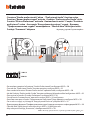
• Comando serratura secondaria • Secondary door lock control • Commande serrure
secondaire • Steuerung zweites Schloss • Mando cerradura secundaria • Bediening
secundair slot • Comando da fechadura secundária • Εντολή δευτερεύουσα
κλειδαριά • • İkincil kilit
kumandası • Sterowanie zamkiem drugorzędnym ·
*
• Inserire il configuratore fornito a corredo • Connect the configurator supplied as standard
•
Mettre en place le configurateur fourni à cet effet
• Den mitgelieferten Konfigurator einsetzen
• Inserte el configurador suministrado
• Breng de standaard geleverde configurator aan
• Inserir o configurador fornecido no equipamento base • Εισάγετε τον διαορφωτή που χορηγείται στον εξοπλισό
• , • Donanım dahlnde tedark edlmş konfgüratörü takın
• Umieścić konfigurator będący na wyposażeniu
5
BUS
1
ET
2 1
3
2
1
O
2
PS
BUS TK
BUS PI
346830
BUS
PL S+
S-
5
BUS
1
ET
2 1
3
2
1
O
2
BUS 2 1
230 Vac
}
346000
0322 06
IP30
PRI 230V~ 50 - 60Hz 260mA
BUS
2-1
27V 1,2A
PRI
346230
1 2 PL S+ S-
J
M
P
J
M
P
ON = 4’’
346230
N
= –
= –
P
= –
= –
MOD = –
P
= –
= –
N
= –
= –
T = –
S = –
N
= –
= *1
P
= –
= –
MOD = –
P
= –
= *1
T = –
M = –
J1 = JMP
J2 = JMP
* 3501/1
Pagina se încarcă...
-
 1
1
-
 2
2
-
 3
3
-
 4
4
-
 5
5
-
 6
6
-
 7
7
-
 8
8
-
 9
9
-
 10
10
-
 11
11
-
 12
12
-
 13
13
-
 14
14
-
 15
15
-
 16
16
-
 17
17
-
 18
18
-
 19
19
-
 20
20
-
 21
21
-
 22
22
-
 23
23
-
 24
24
-
 25
25
-
 26
26
-
 27
27
-
 28
28
-
 29
29
-
 30
30
-
 31
31
-
 32
32
-
 33
33
-
 34
34
-
 35
35
-
 36
36


Bticino 369111 Instrucțiuni de utilizare
- Tip
- Instrucțiuni de utilizare
- Acest manual este potrivit și pentru
în alte limbi
- Türkçe: Bticino 369111 Kullanma talimatları
- français: Bticino 369111 Mode d'emploi
- English: Bticino 369111 Operating instructions
- polski: Bticino 369111 Instrukcja obsługi
- Deutsch: Bticino 369111 Bedienungsanleitung
- italiano: Bticino 369111 Istruzioni per l'uso
- español: Bticino 369111 Instrucciones de operación
- português: Bticino 369111 Instruções de operação
- Nederlands: Bticino 369111 Handleiding
Lucrări înrudite
-
Bticino 368721 Instrucțiuni de utilizare
-
-
-
Bticino F72N32FV1 Instrucțiuni de utilizare
-
-
-
-
-
-