Makita UA004GZ Manual de utilizare
- Categorie
- Unelte electrice
- Tip
- Manual de utilizare

UA004G
EN Cordless Telescopic
Pole Saw INSTRUCTION MANUAL 10
SL Brezžična teleskopska
višinska žaga NAVODILA ZA UPORABO 23
SQ Sharrë teleskopike me bosht
me bateri MANUALI I PËRDORIMIT 36
BG Акумулаторна телескопична
резачка за клони РЪКОВОДСТВО ЗА
ЕКСПЛОАТАЦИЯ 50
HR Bežična teleskopska štapna
pila PRIRUČNIK S UPUTAMA 65
МК Безжична телескопска пила
за столбови УПАТСТВО ЗА УПОТРЕБА 78
SR Бежична тестера са
телескопском цеви УПУТСТВО ЗА УПОТРЕБУ 93
RO Motoferăstrău telescopic
fără r MANUAL DE INSTRUCŢIUNI 107
UK Акумуляторна телескопічна
штангова ланцюгова пила ІНСТРУКЦІЯ З
ЕКСПЛУАТАЦІЇ 121
RU Высоторез аккумуляторный
телескопический РУКОВОДСТВО ПО
ЭКСПЛУАТАЦИИ 136

2
3
1
24
5
67
8
9
10 11
12 13
14
15
Fig.1
2 3
1
1
Fig.2
12
Fig.3
1
2
Fig.4

3
2
1
Fig.5
1
2
Fig.6
11
1
2
3
Fig.7
1
Fig.8
1
2
Fig.9
1
Fig.10
1
Fig.11

4
1 2
3
Fig.12
1
2
Fig.13
1
Fig.14
2 31
Fig.15
1
Fig.16
2
1
Fig.17
2
1
3
4
Fig.18
1
Fig.19

5
12
Fig.20
1
Fig.21
1
2
3
Fig.22
1
Fig.23
1
Fig.24
1
23
Fig.25

6
1
2
Fig.26
Fig.27
1
Fig.28
Fig.29
2
1
Fig.30
1
Fig.31
1
Fig.32
Fig.33

7
1
2
Fig.34
Fig.35
1
2
Fig.36
1
2
Fig.37
1
2
Fig.38
1
Fig.39
1
Fig.40

8
1
2
Fig.41
1
Fig.42
22
11
31
Fig.43
30
30
55 55
Fig.44
1
2
Fig.45
30 1/5
1
Fig.46
Fig.47
Fig.48

9
Fig.49
1
2
Fig.50
2
1
Fig.51

10 ENGLISH
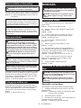
ENGLISH (Original instructions)
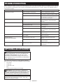
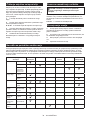
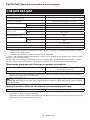
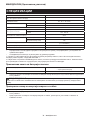
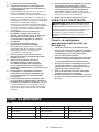
SPECIFICATIONS
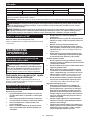
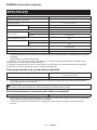
Model: UA004G
Overall length
(without guide bar and battery) 2,516 - 3,748 mm
Rated voltage D.C. 36 V - 40 V max
Net weight *1 7.8 kg
*2 7.8 - 9.1 kg
Standard guide bar length 300 mm
Recommended guide bar
length with 90PX 250 - 300 mm
with 91PX 250 - 300 mm
Applicable saw chain type
(refer to the table below) 90PX
91PX
Standard sprocket Number of teeth 6
Pitch 3/8″
Chain speed 0 - 20 m/s
(0 - 1,200 m/min)
Chain oil tank volume 160 cm3
Protection degree IPX4
• Duetoourcontinuingprogramofresearchanddevelopment,thespecicationshereinaresubjecttochange
without notice.
• Specicationsmaydierfromcountrytocountry.
*1: Weight, with largest battery cartridge and empty oil tank, and without guide bar, chain, and shoulder harness,
according to EN ISO11680-1.
*2:Thelightestandheaviestcombinationofweight,accordingtoEPTA-Procedure01/2014.Theweightmaydier
depending on the attachment(s), including the battery cartridge.
Applicable battery cartridge and charger
Battery cartridge BL4020 / BL4025 / BL4040* / BL4050F* / BL4080F*
* : Recommended battery
Charger DC40RA / DC40RB / DC40RC
• Some of the battery cartridges and chargers listed above may not be available depending on your region of
residence.
WARNING: Only use the battery cartridges and chargers listed above. Use of any other battery cartridges
andchargersmaycauseinjuryand/orre.
Recommended cord connected power source
Portable power pack PDC01 / PDC1200
• The cord connected power source(s) listed above may not be available depending on your region of residence.
• Before using the cord connected power source, read instruction and cautionary markings on them.

11 ENGLISH
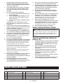
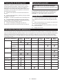
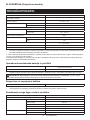
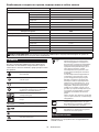
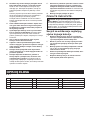
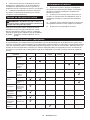
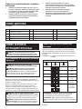
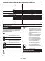
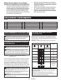
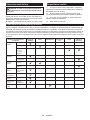
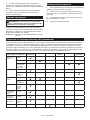
Saw chain, guide bar, and sprocket combination
Saw chain type 90PX
Number of drive links 46
Guide bar Guide bar length 300 mm
Cutting length 296 mm
Pitch 3/8″
Gauge 1.1 mm
Type Sprocket nose bar
Sprocket Number of teeth 6
Pitch 3/8″
Saw chain type 91PX
Number of drive links 46
Guide bar Guide bar length 300 mm
Cutting length 296 mm
Pitch 3/8″
Gauge 1.3 mm
Type Sprocket nose bar
Sprocket Number of teeth 6
Pitch 3/8″
WARNING:Useappropriatecombinationoftheguidebarandsawchain.Otherwisepersonalinjurymay
result.
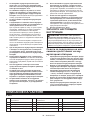
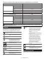
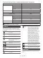
Symbols
The followings show the symbols which may be used
for the equipment. Be sure that you understand their
meaning before use.
Read instruction manual.
Wear a helmet, goggles and ear protection.
Wear protective gloves.
Wear sturdy boots with nonslip soles.
Steeltoed safety boots are recommended.
Beware of electrical lines, risk of electrical
shock.
Keep distance at least 15 m.
Maximum permissible cut length
Direction of chain travel
Chain oil tank
Hotsurfaces-Burnstongersorhands.
Ni-MH
Li-ion Only for EU countries
Due to the presence of hazardous com-
ponents in the equipment, waste electrical
and electronic equipment, accumulators
and batteries may have a negative impact
on the environment and human health.
Do not dispose of electrical and electronic
appliances or batteries with household
waste!
In accordance with the European Directive
on waste electrical and electronic equip-
ment and on accumulators and batteries
and waste accumulators and batteries,
as well as their adaptation to national law,
waste electrical equipment, batteries and
accumulators should be stored separately
and delivered to a separate collection point
for municipal waste, operating in accor-
dance with the regulations on environmen-
tal protection.
This is indicated by the symbol of the
crossed-out wheeled bin placed on the
equipment.
Guaranteed sound power level according
to EU Outdoor Noise Directive.
Sound power level according to Australia
NSW Noise Control Regulation.
Intended use
The tool is intended for pruning branches and limbs.

12 ENGLISH
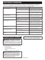
Noise
The typical A-weighted noise level determined accord-
ing to ISO22868(ISO11680-1):
Sound pressure level (LpA) : 90 dB (A)
Sound power level (LWA) : 105 dB (A)
Uncertainty (K) : 3 dB (A)
NOTE: The declared noise emission value(s) has
been measured in accordance with a standard test
method and may be used for comparing one tool with
another.
NOTE: The declared noise emission value(s)
may also be used in a preliminary assessment of
exposure.
WARNING: Wear ear protection.
WARNING: The noise emission during actual
use of the power tool can dier from the declared
value(s) depending on the ways in which the
tool is used especially what kind of workpiece is
processed.
WARNING: Be sure to identify safety mea-
sures to protect the operator that are based on an
estimation of exposure in the actual conditions of
use (taking account of all parts of the operating
cycle such as the times when the tool is switched
o and when it is running idle in addition to the
trigger time).
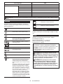
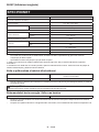
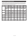
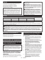
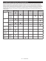
Vibration
Left handle (Front grip) Right handle (Rear grip) Applicable standard
ah (m/s2)Uncertainty K (m/s2)ah (m/s2)Uncertainty K (m/s2)
2.5 1.5 3.1 1.5 ISO22867(ISO11680-1)
NOTE: The declared vibration total value(s) has been measured in accordance with a standard test method and
may be used for comparing one tool with another.
NOTE: The declared vibration total value(s) may also be used in a preliminary assessment of exposure.
WARNING: The vibration emission during actual use of the power tool can dier from the declared
value(s) depending on the ways in which the tool is used especially what kind of workpiece is processed.
WARNING: Be sure to identify safety measures to protect the operator that are based on an estimation
of exposure in the actual conditions of use (taking account of all parts of the operating cycle such as the
times when the tool is switched o and when it is running idle in addition to the trigger time).
EC Declaration of Conformity
For European countries only
The EC declaration of conformity is included as Annex A
to this instruction manual.
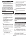
SAFETY WARNINGS
General power tool safety warnings
WARNING: Read all safety warnings, instruc-
tions, illustrations and specications provided
with this power tool. Failure to follow all instructions
listedbelowmayresultinelectricshock,reand/or
seriousinjury.
Save all warnings and instruc-
tions for future reference.
The term "power tool" in the warnings refers to your
mains-operated (corded) power tool or battery-operated
(cordless) power tool.
Cordless Telescopic Pole Saw
Safety Warnings
General precautions
1. Before starting the tool, read this instruction
manual to become familiar with the handling of
the tool.
2. Do not lend the tool to a person with insu-
cient experience or knowledge regarding han-
dling of the tool.
3. When lending the tool, always attach this
instruction manual.
4. Do not allow children or young persons under
18 years old to use the tool. Keep them away
from the tool.
5. Handle the tool with the utmost care and
attention.
6. Never use the tool after consuming alcohol or
drugs, or if feeling tired or ill.
7. Never attempt to modify the tool.
8.
Do not use the tool in bad weather conditions,
especially when there is a risk of lightning. This
decreases the risk of being struck by lightning.
9. National regulations may restrict of the use of
the tool. Follow the regulations about handling
of the tool in your country.
Personal protective equipment
1. Wear safety helmet, protective goggles and
protective gloves to protect yourself from
ying debris or falling objects.

13 ENGLISH
2. Wear ear protection such as ear mus to pre-
vent hearing loss.
3. Wear proper clothing and shoes for safe
operation, such as a work overall and sturdy,
non-slip shoes. Do not wear loose clothing or
jewelry.Looseclothes,jewelryorlonghaircanbe
caught in moving parts.
4. When handling the saw chain or adjusting the
chain tension, wear protective gloves. Saw
chain can cut bare hands severely.
Work area safety
1. Keep the tool at least 15 m away from electric
lines and communication cables (including
any branches contacting them). Touching or
approaching high-voltage lines with the tool
can result in death or serious injury. Watch
power lines and electrical fences around the
work area before starting operation.
2. Operate the tool under good visibility and day-
light conditions only. Do not operate the tool in
darkness or fog.
3. During operation, never stand on an unstable
or slippery surface or a steep slope. During
the cold season, beware of ice and snow and
always ensure secure footing.
4. During operation, keep bystanders or animals
at least 15 m away from the tool. Stop the tool
as soon as someone approaches.
5. When working with two or more people, keep a
distance of at least 15 m or more between each
other, and put a supervisor.
6. Before operation, examine the work area for
wire fences, walls, or other solid objects. They
can damage the saw chain.
Preparation
1.
Before assembling or adjusting the tool, switch
o the tool and remove the battery cartridge.
2. Before handling the saw chain or adjusting the
chain tension, wear protective gloves.
3. Before starting the tool, inspect the tool for
damages, loose screws/nuts or improper
assembly. Sharpen blunt saw chain. If the saw
chain is bent or damaged, replace it. Check all
control levers and switches for easy action.
Clean and dry the grips.
4. Never attempt to start the tool if the tool is
damaged or not fully assembled. Otherwise
seriousinjurymayresult.
5. Adjust the shoulder harness to suit the opera-
tor’s body size.
6. Adjust the chain tension properly. Rell the
chain oil, if necessary.
Starting the tool
1. Wear the personal protective equipments
before starting the tool.
2. Before starting the tool, make sure that there
is no person or animal in the work area.
3. When installing the battery cartridge, keep
the saw chain and guide bar clear of your
body and other object, including the ground.
The saw chain may move when starting and may
causeseriousinjuryordamagetothesawchain
and/or property.
4. Place the tool on rm ground. Maintain good
balance and secure footing.
Operation
1. In the event of an emergency, switch o the
tool immediately.
2. If you notice any unusual condition (e.g. noise,
vibration) during operation, switch o the tool.
Do not use the tool until the cause is recog-
nized and solved.
3. The saw chain continues to move for a short
period after switching o the tool. Don’t rush
to contact the saw chain.
4. During operation, use the shoulder harness.
Keep the tool on your right side rmly.
5. Hold the front grip with your left hand and the
rear grip with your right hand, no matter you
are right-hander or left-hander. Wrap your
ngers and thumbs around the grips.
6. Hold the tool by insulated gripping surfaces
only, because the saw chain may contact hid-
den wiring. A saw chain contacting a “live” wire
may make exposed metal parts of the extend-
ed-reach pruner “live” and could give the operator
an electric shock.
7. Never attempt to operate the tool with one
hand. Loss of control may result in serious or
fatal injury. To reduce the risk of injury, keep
your hands and feet away from the saw chain.
8. Do not overreach. Keep proper footing and
balance at all times. Watch for hidden obsta-
cles such as tree stumps, roots and ditches
to avoid stumbling. Clear fallen branches and
other objects away.
9. Never work on a ladder or tree to avoid loss of
control.
10. If the tool gets heavy impact or fall, check the
condition before continuing work. If there is
any damage or doubt, ask Makita authorized
service center for the inspection and repair.
11. Do not touch the head of the tool. The head of
the tool becomes hot during operation.
12. Take a rest to prevent loss of control caused
by fatigue. We recommend to take a 10 to
20-minute rest every hour.
13. When you leave the tool, even if it is a short
time, always switch o the tool and remove the
battery cartridge. The running and unattended
tool may be used by unauthorized person and
cause serious accident.
14. When operating the tool, do not raise your
right hand above your shoulder height.
15. During operation, never hit the saw chain
against hard obstacles such stones and nails.
Take particular care when cutting branches
next to walls, wire fences or the like.
16.
If branches get caught in the tool, always stop the
tool and remove the battery cartridge. Otherwise
unintentionalstartmaycauseseriousinjury.
17. If the saw chain becomes clogged, always
switch o the tool and remove the battery
cartridge before cleaning.
18. Accelerating the tool with the saw chain
blocked increases the load and will damage
the tool.

14 ENGLISH
19. Before cutting limbs, keep an escape area
away from the falling limb. First, clear
obstructs such as limbs and branches from
the work area. Move all tools and goods from
the escape area to another safe place.
20. Before cutting branches and limbs, check
the falling direction of them, considering the
condition of branches and limbs, adjoining
trees, wind direction, etc. Pay full attention to
the falling direction, and the rebound of the
branch, which hit the ground.
21. Never hold the tool at an angle of more than
60°. Otherwise falling objects can hit the oper-
ator and cause serious injury. Never stand
underneath the limb being cut.
22. Pay attention to broken or bent branches. They
may bounce back in cutting, causing unexpected
injury.
23. Before cutting limbs that you intend to cut,
remove branches and leaves around them.
Otherwise the saw chain may be caught by them.
24. To prevent the saw chain from being caught in
the kerf, do not release the lever before pulling
the saw chain out of the kerf.
25. If the saw chain is bound in the kerf, immedi-
ately stop the tool, carefully move the branch
to open the kerf and release the saw chain.
26. Avoid kickback (rotational reactive force
towards the operator). To prevent kickback,
never use the guide bar nose or perform a
penetrating cut. Always beware of the position
of the guide bar nose.
27. Check the chain tension frequently. When
checking or adjusting the chain tension,
switch o the tool and remove the battery
cartridge. If the tension is loose, tighten it.
28. When you use the tool on muddy ground, wet
slope, or slippery place, pay attention to your
footing.
29. Do not submerge the tool into a puddle.
30. Do not leave the tool unattended outdoors in
the rain.
Transport
1. Before transporting the tool, switch o the tool
and remove the battery cartridge. Always t
the guide bar cover during transportation.
2. When transporting the tool, carry it in a hori-
zontal position by holding the grip.
Maintenance
1. Have your equipment serviced by our autho-
rized service center, always using only genu-
ine replacement parts. Incorrect repair and poor
maintenance can shorten the life of the tool and
increase the risk of accidents.
2. Before doing any maintenance or repair work
or cleaning the tool, always switch o the tool
and remove the battery cartridge. Wait until the
tool cools down.
3. Always wear protective gloves when handling
the saw chain.
4. After each use, tighten all screws and nuts,
except for adjustment screws.
5. Keep the saw chain sharp. If the saw chain
has become blunt and cutting performance is
poor, ask Makita authorized service center to
sharpen it or replace it with new one.
6. Do not attempt any maintenance or repair
not described in this instruction manual. Ask
Makita authorized service center for such
work.
7. Always use Makita genuine spare parts and
accessories only. Using parts or accessories
supplied by a third party may result in the tool
breakdown, property damage and/or serious
injury.
Storage
1. Before storing the tool, perform full cleaning
and maintenance. Fit the guide bar cover.
Remove the battery cartridge. Drain the chain
oil after the tool cools down.
2. Store the tool in a dry and high or locked loca-
tion out of reach of children.
3. Do not prop the tool against something, such
as a wall. Otherwise it may fall suddenly and
causeaninjury.
4. When storing the tool, avoid direct sunlight
and rain, and store it in a place where it does
not get hot or humid.
Electrical and battery safety
1. Do not dispose of the battery(ies) in a re.
The cell may explode. Check with local codes for
possible special disposal instructions.
2. Do not open or mutilate the battery(ies).
Released electrolyte is corrosive and may cause
damage to the eyes or skin. It may be toxic if
swallowed.
3. Do not charge battery in rain, or in wet
locations.
4. Do not charge the battery outdoors.
5. Do not handle charger, including charger plug,
and charger terminals with wet hands.
6. Avoid dangerous environment. Don't use the
tool in dump or wet locations or expose it to
rain. Water entering the tool will increase the risk
of electric shock.
7. Do not replace the battery in the rain.
SAVE THESE INSTRUCTIONS.
WARNING: DO NOT let comfort or familiarity
with product (gained from repeated use) replace
strict adherence to safety rules for the subject
product. MISUSE or failure to follow the safety
rules stated in this instruction manual may cause
serious personal injury.
Important safety instructions for
battery cartridge
1. Before using battery cartridge, read all instruc-
tions and cautionary markings on (1) battery
charger, (2) battery, and (3) product using
battery.
2. Do not disassemble or tamper with the battery
cartridge.Itmayresultinare,excessiveheat,
or explosion.

15 ENGLISH
3. If operating time has become excessively
shorter, stop operating immediately. It may
result in a risk of overheating, possible burns
and even an explosion.
4. If electrolyte gets into your eyes, rinse them
out with clear water and seek medical atten-
tion right away. It may result in loss of your
eyesight.
5. Do not short the battery cartridge:
(1) Do not touch the terminals with any con-
ductive material.
(2) Avoid storing battery cartridge in a con-
tainer with other metal objects such as
nails, coins, etc.
(3) Do not expose battery cartridge to water
or rain.
A battery short can cause a large current
ow, overheating, possible burns and even a
breakdown.
6. Do not store and use the tool and battery car-
tridge in locations where the temperature may
reach or exceed 50 °C (122 °F).
7. Do not incinerate the battery cartridge even if
it is severely damaged or is completely worn
out. The battery cartridge can explode in a re.
8. Do not nail, cut, crush, throw, drop the battery
cartridge, or hit against a hard object to the
battery cartridge. Such conduct may result in a
re,excessiveheat,orexplosion.
9. Do not use a damaged battery.
10.
The contained lithium-ion batteries are subject to
the Dangerous Goods Legislation requirements.
For commercial transports e.g. by third parties,
forwarding agents, special requirement on pack-
aging and labeling must be observed.
For preparation of the item being shipped, consult-
ing an expert for hazardous material is required.
Please also observe possibly more detailed
national regulations.
Tapeormaskoopencontactsandpackupthe
battery in such a manner that it cannot move
around in the packaging.
11. When disposing the battery cartridge, remove
it from the tool and dispose of it in a safe
place. Follow your local regulations relating to
disposal of battery.
12. Use the batteries only with the products
specied by Makita. Installing the batteries to
non-compliantproductsmayresultinare,exces-
sive heat, explosion, or leak of electrolyte.
13. If the tool is not used for a long period of time,
the battery must be removed from the tool.
14. During and after use, the battery cartridge may
take on heat which can cause burns or low
temperature burns. Pay attention to the han-
dling of hot battery cartridges.
15. Do not touch the terminal of the tool imme-
diately after use as it may get hot enough to
cause burns.
16. Do not allow chips, dust, or soil stuck into the
terminals, holes, and grooves of the battery
cartridge.Itmaycauseheating,catchingre,
burst and malfunction of the tool or battery car-
tridge,resultinginburnsorpersonalinjury.
17. Unless the tool supports the use near
high-voltage electrical power lines, do not use
the battery cartridge near a high-voltage elec-
trical power lines. It may result in a malfunction
or breakdown of the tool or battery cartridge.
18. Keep the battery away from children.
SAVE THESE INSTRUCTIONS.
CAUTION: Only use genuine Makita batteries.
Use of non-genuine Makita batteries, or batteries that
have been altered, may result in the battery bursting
causingres,personalinjuryanddamage.Itwill
also void the Makita warranty for the Makita tool and
charger.
Tips for maintaining maximum
battery life
1. Charge the battery cartridge before completely
discharged. Always stop tool operation and
charge the battery cartridge when you notice
less tool power.
2. Never recharge a fully charged battery car-
tridge. Overcharging shortens the battery
service life.
3. Charge the battery cartridge with room tem-
perature at 10 °C - 40 °C (50 °F - 104 °F). Let
a hot battery cartridge cool down before
charging it.
4. When not using the battery cartridge, remove
it from the tool or the charger.
5. Charge the battery cartridge if you do not use
it for a long period (more than six months).
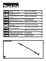
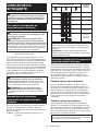
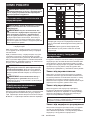
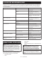
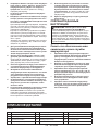
PARTS DESCRIPTION
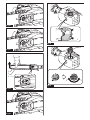
►Fig.1
1Main power lamp 2Main power switch 3Hanger
4Lock-olever 5Battery cartridge 6Switch trigger
7Rear grip 8Saw chain 9Guide bar
10 Oil tank cap 11 Lock ring 12 Retaining nut
13 Chainadjustingscrew 14 Guide bar cover 15 Front grip

16 ENGLISH
FUNCTIONAL DESCRIPTION
CAUTION: Always be sure that the tool is
switched o and the battery cartridge is removed
before adjusting or checking function on the tool.
Installing or removing battery cartridge
CAUTION: Always switch o the tool before
installing or removing of the battery cartridge.
CAUTION: Hold the tool and the battery car-
tridge rmly when installing or removing battery
cartridge. Failure to hold the tool and the battery
cartridgermlymaycausethemtoslipoyourhands
and result in damage to the tool and battery cartridge
andapersonalinjury.
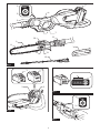
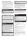
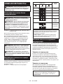
►Fig.2: 1. Red indicator 2. Button 3. Battery cartridge
To remove the battery cartridge, slide it from the tool
while sliding the button on the front of the cartridge.
To install the battery cartridge, align the tongue on the
battery cartridge with the groove in the housing and slip
it into place. Insert it all the way until it locks in place
with a little click. If you can see the red indicator as
showninthegure,itisnotlockedcompletely.
CAUTION: Always install the battery cartridge
fully until the red indicator cannot be seen. If not,
itmayaccidentallyfalloutofthetool,causinginjuryto
you or someone around you.
CAUTION: Do not install the battery cartridge
forcibly. If the cartridge does not slide in easily, it is
not being inserted correctly.
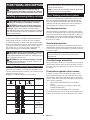
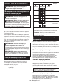
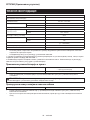
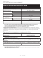
Indicating the remaining battery capacity
Press the check button on the battery cartridge to indi-
cate the remaining battery capacity. The indicator lamps
light up for a few seconds.
►Fig.3: 1. Indicator lamps 2. Check button
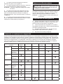
Indicator lamps Remaining
capacity
Lighted O Blinking
75% to 100%
50% to 75%
25% to 50%
0% to 25%
Charge the
battery.
The battery
may have
malfunctioned.
NOTE: Depending on the conditions of use and the
ambienttemperature,theindicationmaydierslightly
from the actual capacity.
NOTE:Therst(farleft)indicatorlampwillblinkwhen
the battery protection system works.
Tool / battery protection system
The tool is equipped with a tool/battery protection sys-
tem.Thissystemautomaticallycutsopowertothe
motor to extend tool and battery life. The tool will auto-
matically stop during operation if the tool or battery is
placed under one of the following conditions:
Overload protection
When the battery is operated in a manner that causes
it to draw an abnormally high current, the tool automati-
cally stops and the main power lamp blinks in green. In
thissituation,turnthetooloandstoptheapplication
that caused the tool to become overloaded. Then turn
the tool on to restart.
Overheat protection
When the tool or battery is overheated, the tool stops
automatically and the main power lamp lights up in red.
In this case, let the tool and battery cool before turning
the tool on again.
NOTE: In high temperature environment, the over-
heat protection likely to work and the tool stops
automatically.
Overdischarge protection
When the battery capacity is not enough, the tool stops
automatically and the main power lamp blinks in red. In
this case, remove the battery from the tool and charge
the battery.
Protections against other causes
Protection system is also designed for other causes
that could damage the tool and allows the tool to stop
automatically. Take all the following steps to clear the
causes, when the tool has been brought to a temporary
halt or stop in operation.
1. Turnthetoolo,andthenturnitonagainto
restart.
2. Charge the battery(ies) or replace it/them with
recharged battery(ies).
3. Let the machine and battery(ies) cool down.
If no improvement can be found by restoring protection
system, then contact your local Makita Service Center.

17 ENGLISH
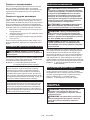
Main power switch
WARNING: Always turn o the main power
switch when not in use.
To turn on the tool, press the main power switch. To turn
o,pressthemainpowerswitchagain.
►Fig.4: 1. Main power lamp 2. Main power switch
NOTE: The main power lamp blinks in green when
you turn on the main power switch while holding down
thelock-oleverandpullingtheswitchtrigger.Inthis
case,releasetheswitchtriggerandthelock-olever,
and then turn on the main power switch.
NOTE:Thistoolemploystheautopower-ofunction.
To avoid unintentional start up, the main power switch
will automatically shut down when the switch trigger
is not pulled for a certain period after the main power
switch is turned on.
Switch action
WARNING: For your safety, this tool is
equipped with lock-o lever which prevents the
tool from unintended starting. NEVER use the tool
if it runs when you simply pull the switch trigger
without pressing the lock-o lever. Return the
tool to our authorized service center for proper
repairs BEFORE further usage.
WARNING: NEVER tape down or defeat pur-
pose and function of lock-o lever.
CAUTION: Before installing the battery car-
tridge into the tool, always check to see that the
switch trigger actuates properly and returns to
the "OFF" position when released.
NOTICE: Do not pull the switch trigger hard with-
out pressing the lock-o lever. This can cause
switch breakage.
To prevent the switch trigger from being accidentally
pulled,alock-oleverisprovided.Tostartthetool,
depressthelock-oleverandpulltheswitchtrigger.
The tool speed increases by increasing pressure on the
switch trigger. Release the switch trigger to stop.
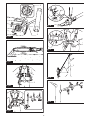
►Fig.5: 1. Switch trigger 2.Lock-olever
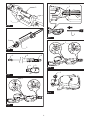
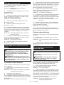
Adjusting the pipe length
To extend or shorten the pipe, loosen the lock ring by
turningthelockringcounterclockwise,thenadjustthe
length of the pipe, and then tighten the ring by turning
the lock ring clockwise.
►Fig.6: 1. Lock ring 2. Pipe
ASSEMBLY
CAUTION: Always be sure that the tool is
switched o and the battery cartridge is removed
before carrying out any work on the tool.
CAUTION: Do not touch the saw chain with
bare hands. Always wear gloves when handling
the saw chain.
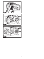
Assembling the tool
1. Remove 2 caps from the pipe, and 1 cap from the
head of the tool.
►Fig.7: 1. Cap 2. Pipe 3. Head of tool
2. Loosen 3 bolts, and then remove 1 bolt using the
hex wrench.
►Fig.8: 1. Bolt
3.
Insert the pipe into the tool body all the way, and then
align the hole on the pipe with the hole on the tool body.
►Fig.9: 1. Hole 2. Pipe
4. Tighten 3 bolts using the hex wrench.
►Fig.10: 1. Bolt
5. Loosen 2 bolts, and then remove 1 bolt.
►Fig.11: 1. Bolt
6. Loosen the lock ring by turning the lock ring coun-
terclockwise, then extend the pipe approximately 10 cm
or more, and then tighten the lock ring by turning the
lock ring clockwise.
►Fig.12: 1. Lock ring 2. 10 cm or more 3. Pipe
7. Insert the pipe into the head of the tool all the way,
and then align the hole on the pipe with the hole on the
head of the tool.
►Fig.13: 1. Hole 2. Pipe
8. Tighten 2 bolts using the hex wrench.
►Fig.14: 1. Bolt
Installing or removing saw chain
CAUTION: The saw chain and the guide bar
are still hot just after the operation. Let them cool
down enough before carrying out any work on
the tool.
CAUTION: Carry out the procedure of install-
ing or removing saw chain in a clean place free
from sawdust and the like.
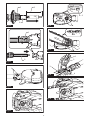
Installing the saw chain
To install the saw chain, perform the following steps:
1.
Loosenthechainadjustingscrew,thentheretainingnut.
►Fig.15: 1. Retaining nut 2.Chainadjustingscrew
3. Sprocket cover
2. Remove the sprocket cover.
3. Check the direction of the saw chain. Match the
direction of the saw chain with that of the mark on the
tool body.
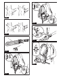
►Fig.16: 1. Mark on chain saw body

18 ENGLISH
4. Fit one end of the saw chain on the top of the
guide bar. Fit the other end of the saw chain around the
sprocket.Makesurethatthesawchainisproperlytted
onthesprocketandproperlyttedinthegrooveofthe
guide bar.
5. Attach the guide bar to the tool body, aligning the
hole on the guide bar with the pin on the tool body.
►Fig.17: 1. Hole 2. Sprocket
6. Insert the protrusion on the sprocket cover to the
tool body, and then close the cover so that the bolt and
pin on the tool body meet their counterparts on the
cover.
►Fig.18: 1. Sprocket cover 2. Protrusion 3. Bolt
4. Pin
7. Tighten the retaining nut to secure the sprocket
cover,thenloosenitabitfortensionadjustment.
►Fig.19: 1. Retaining nut
Afterinstallingthesawchain,adjustthesawchain
tensionbyreferringtothesectionforadjustingsaw
chain tension.
Removing the saw chain
To remove the saw chain, perform the following steps:
1. Loosenthechainadjustingscrew,thentheretain-
ing nut.
►Fig.20: 1. Retaining nut 2.Chainadjustingscrew
2. Remove the sprocket cover, and then remove the
saw chain and guide bar from the tool body.
Adjusting saw chain tension
CAUTION: Do not tighten the saw chain too
much. Excessively high tension of saw chain may
cause breakage of saw chain and wear of the guide
bar.
CAUTION: A chain which is too loose can
jump o the bar and it may cause an injury
accident.
The saw chain may become loose after many hours
of use. From time to time check the saw chain tension
before use.
1. Loosen the retaining nut a bit to loosen the
sprocket cover lightly.
►Fig.21: 1. Retaining nut
2. Liftuptheguidebartipslightlyandadjustthe
chaintension.Turnthechainadjustingscrewcounter-
clockwise to tighten, turn it clockwise to loosen.
Tighten the saw chain until the lower side of the saw
chaintsintheguidebarrailasillustrated.
►Fig.22: 1. Guide bar 2. Saw chain 3.Chainadjust-
ing screw
3. Keep holding the guide bar lightly and attach the
sprocket cover.
Make sure that the saw chain does not loose at the
lower side.
4. Tighten the retaining nut to secure the sprocket
cover.
►Fig.23: 1. Retaining nut
OPERATION
Lubrication
NOTICE: When lling the chain oil for the rst
time, or relling the tank after it has been com-
pletely emptied, add oil up to the bottom edge of
the ller neck. The oil delivery may otherwise be
impaired.
NOTICE: Use the saw chain oil exclusively for
Makita chain saws or equivalent oil available in
the market.
NOTICE: Never use oil including dust and parti-
cles or volatile oil.
NOTICE: When pruning trees, use botanical oil.
Mineral oil may harm trees.
NOTICE: Before the cutting operation, make sure
that the oil tank cap is tightened securely.
Saw chain is automatically lubricated when the tool is in
operation. Check the amount of remaining oil in the oil
tank periodically.
►Fig.24: 1. Oil tank
Torellthetank,placethetoolonaatsurface,then
push the button on the oil tank cap so that the button on
the other side stands up, and then remove the oil tank
cap by turning it.
Theproperamountofoilis160ml.Afterrellingthe
tank, make sure that the oil tank cap is tightened
securely.
►Fig.25: 1. Oil tank cap 2. Tighten 3. Loosen
NOTE:Ifitisdiculttoremovetheoiltankcap,
insert the box wrench into the slot of the oil tank
cap, and then remove the oil tank cap by turning it
counterclockwise.
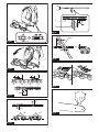
►Fig.26: 1. Slot 2. Box wrench
Afterrelling,holdthetoolawayfromthetree.Startit
and wait until lubrication on saw chain is adequate.
►Fig.27

19 ENGLISH
Attaching the shoulder harness
CAUTION: When you use the tool in combi-
nation of the backpack-type power supply such
as portable power pack, do not use the shoulder
harness included in the tool package, but use the
hanging band recommended by Makita.
If you put on the shoulder harness included in the
tool package and the shoulder harness of the back-
pack-type power supply at the same time, removing
thetoolorbackpack-typepowersupplyisdicultin
case of an emergency, and it may cause an accident
orinjury.Fortherecommendedhangingband,ask
Makita Authorized Service Centers.
CAUTION: Always use the shoulder harness
attached to the tool. Before operation, adjust the
shoulder harness according to the user size to
prevent fatigue.
CAUTION: Before operation, make sure that
the shoulder harness is properly attached to the
hanger on the tool.
CAUTION: Before operation, make sure that
the buckle of the shoulder harness is fastened
rmly.
CAUTION: Always use the shoulder harness
dedicated to this tool. Do not use other shoulder
harnesses.
1.
Put on the shoulder harness and fasten the buckle.
►Fig.28: 1. Buckle
NOTE: When removing the shoulder harness, unlock
the buckle and remove the shoulder harness.
2. Adjusttheshoulderharnesstoacomfortable
working position.
►Fig.29
3.
Clasp the hook on the shoulder harness to tool's hanger.
►Fig.30: 1. Hook 2. Hanger
The shoulder harness features a means of quick
release. Simply squeeze the sides of the buckle to
release the shoulder harness.
►Fig.31: 1. Buckle
Working with the tool
CAUTION: Keep all parts of the body away
from the saw chain when the motor is operating.
CAUTION: Hold the tool rmly with both
hands when the motor is running.
CAUTION: Do not overreach. Keep proper
footing and balance at all times.
CAUTION: When cutting through branches,
be careful not to lose your balance due to the
weight of the tool head.
CAUTION: Always keep escape route in case
a cut branch falls towards the operator.
CAUTION: Never use the tip of the guide bar
for cutting. Otherwise, dangerous kickback may
occur, and it may result in personal injury.
NOTICE: Never toss or drop the tool.
NOTICE: Do not cover the vents of the tool.
NOTICE: Do not force the tool. Otherwise, it may
damage the tool.
Stand on a stable surface, and hold the tool away from
the branches so that the angle of the tool becomes 60°
or less against the horizontal ground.
►Fig.32: 1. 60° or less
Start the tool, and then press the saw chain onto the
branch lightly.
When cutting long branches, in order to control the drop
position of cut branches, divide the branch in sections
and cut the branch from the tip. Pay attention to the
falling branches since they may bounce in the direction
of the operator after hitting the ground.
►Fig.33
Whencuttingthickbranches,rstmakeashallow
undercutandthenmakethenishcutfromthetop.
►Fig.34
Ifyoutrytocutothickbranchesfromthebottom,the
branch may close in and pinch the saw chain in the cut.
Ifyoutrytocutothickbranchesfromthetopwithouta
shallow undercut, the branch may splinter.
►Fig.35
Carrying tool
Before carrying the tool, always remove the battery car-
tridge from the tool, then attach the guide bar cover, and
then shorten the pipe. Also, cover the battery cartridge
with the battery cover.
►Fig.36: 1. Guide bar cover 2. Battery cover
Using the tool with portable power
pack
Optional accessory
Use the hanging band when you use the tool with porta-
ble power pack.
Attaching the hanging band
1. Attach the hooks of the hanging band to the rings
of the shoulder harness or waist belt as shown in the
gure.Selectthetypeofbandandtheconnecting
method appropriate for your usage.
►Fig.37: 1. Ring 2. Hook
►Fig.38: 1. Ring 2. Hook
2. Attach the hook to the tool.
►Fig.39: 1. Hook
Detaching the tool
When setting down the tool, unlock the buckle on the
hanging band with one hand while holding the tool with
the other hand.
►Fig.40: 1. Buckle
NOTE: The buckle is not equipped depending on the
type of band.

20 ENGLISH
If you need to release the tool quickly, follow the steps
below.
1. Push the levers on the buckle of the waist belt to
unlock the buckle.
►Fig.41: 1. Buckle 2. Lever
2. Takeotheshoulderharnesstoreleasethetool
and the unit.
►Fig.42: 1. Shoulder harness
MAINTENANCE
CAUTION: Always be sure that the tool is
switched o and the battery cartridge is removed
before attempting to perform inspection or
maintenance.
CAUTION: Always wear gloves when perform-
ing any inspection or maintenance.
NOTICE: Never use gasoline, benzine, thinner,
alcohol or the like. Discoloration, deformation or
cracks may result.
To maintain product SAFETY and RELIABILITY,
repairs,anyothermaintenanceoradjustmentshould
be performed by Makita Authorized or Factory Service
Centers, always using Makita replacement parts.
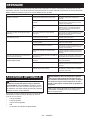
Sharpening the saw chain
Sharpen the saw chain when:
• Mealy sawdust is produced when damp wood is
cut;
• Thechainpenetratesthewoodwithdiculty,even
when heavy pressure is applied;
• The cutting edge is obviously damaged;
• The saw pulls to the left or right in the wood.
(caused by uneven sharpening of the saw chain or
damage to one side only)
Sharpen the saw chain frequently but a little each time.
Twoorthreestrokeswithaleareusuallysucientfor
routine resharpening. When the saw chain has been
resharpened several times, have it sharpened in our
authorized service center.
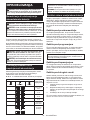
Sharpening criteria:
WARNING: An excessive distance between
the cutting edge and depth gauge increases the
risk of kickback.
►Fig.43: 1. Cutter length 2. Distance between cutting
edge and depth gauge 3. Minimum cutter
length (3 mm)
— Allcutterlengthmustbeequal.Dierentcutter
lengths prevent the saw chain from running
smoothly and may cause the saw chain to break.
— Do not sharpen the chain when the cutter length
has reached 3 mm or shorter. The chain must be
replaced with new one.
— The chip thickness is determined by the distance
between the depth gauge (round nose) and the
cutting edge.
— The best cutting results are obtained with following
distance between cutting edge and depth gauge.
• Chain blade 90PX : 0.65 mm
• Chain blade 91PX : 0.65 mm
►Fig.44
— The sharpening angle of 30° must be the same on
allcutters.Dierentcutteranglescausethechain
to run roughly and unevenly, accelerate wear, and
lead to chain breaks.
— Useasuitableroundlesothatthepropersharp-
ening angle is kept against the teeth.
• Chain blade 90PX : 55°
• Chain blade 91PX : 55°
File and le guiding
— Useaspecialroundle(optionalaccessory)for
saw chains to sharpen the chain. Normal round
lesarenotsuitable.
— Diameteroftheroundleforeachsawchainisas
follows:
• Chain blade 90PX : 4.5 mm
• Chain blade 91PX : 4.0 mm
— Theleshouldonlyengagethecutteronthefor-
wardstroke.Lifttheleothecutteronthereturn
stroke.
— Sharpentheshortestcutterrst.Thenthelength
of this shortest cutter becomes the standard for all
other cutters on the saw chain.
— Guidetheleasshowninthegure.
►Fig.45: 1. File 2. Saw chain
— Thelecanbeguidedmoreeasilyifaleholder
(optionalaccessory)isemployed.Theleholder
has markings for the correct sharpening angle of
30° (align the markings parallel to the saw chain)
and limits the depth of penetration (to 4/5 of the
lediameter).
►Fig.46: 1. File holder
— After sharpening the chain, check the height of the
depth gauge using the chain gauge tool (optional
accessory).
►Fig.47
— Removeanyprojectingmaterial,howeversmall,
withaspecialatle(optionalaccessory).
— Roundothefrontofthedepthgaugeagain.
Cleaning the guide bar
Chips and sawdust will build up in the guide bar groove.
Theymayclogthebargrooveandimpairtheoilow.
Clean out the chips and sawdust every time when you
sharpen or replace the saw chain.
►Fig.48
Cleaning the sprocket cover
Chips and saw dust will accumulate inside of the
sprocket cover. Remove the sprocket cover and saw
chain from the tool then clean the chips and saw dust.
►Fig.49
Pagina se încarcă...
Pagina se încarcă...
Pagina se încarcă...
Pagina se încarcă...
Pagina se încarcă...
Pagina se încarcă...
Pagina se încarcă...
Pagina se încarcă...
Pagina se încarcă...
Pagina se încarcă...
Pagina se încarcă...
Pagina se încarcă...
Pagina se încarcă...
Pagina se încarcă...
Pagina se încarcă...
Pagina se încarcă...
Pagina se încarcă...
Pagina se încarcă...
Pagina se încarcă...
Pagina se încarcă...
Pagina se încarcă...
Pagina se încarcă...
Pagina se încarcă...
Pagina se încarcă...
Pagina se încarcă...
Pagina se încarcă...
Pagina se încarcă...
Pagina se încarcă...
Pagina se încarcă...
Pagina se încarcă...
Pagina se încarcă...
Pagina se încarcă...
Pagina se încarcă...
Pagina se încarcă...
Pagina se încarcă...
Pagina se încarcă...
Pagina se încarcă...
Pagina se încarcă...
Pagina se încarcă...
Pagina se încarcă...
Pagina se încarcă...
Pagina se încarcă...
Pagina se încarcă...
Pagina se încarcă...
Pagina se încarcă...
Pagina se încarcă...
Pagina se încarcă...
Pagina se încarcă...
Pagina se încarcă...
Pagina se încarcă...
Pagina se încarcă...
Pagina se încarcă...
Pagina se încarcă...
Pagina se încarcă...
Pagina se încarcă...
Pagina se încarcă...
Pagina se încarcă...
Pagina se încarcă...
Pagina se încarcă...
Pagina se încarcă...
Pagina se încarcă...
Pagina se încarcă...
Pagina se încarcă...
Pagina se încarcă...
Pagina se încarcă...
Pagina se încarcă...
Pagina se încarcă...
Pagina se încarcă...
Pagina se încarcă...
Pagina se încarcă...
Pagina se încarcă...
Pagina se încarcă...
Pagina se încarcă...
Pagina se încarcă...
Pagina se încarcă...
Pagina se încarcă...
Pagina se încarcă...
Pagina se încarcă...
Pagina se încarcă...
Pagina se încarcă...
Pagina se încarcă...
Pagina se încarcă...
Pagina se încarcă...
Pagina se încarcă...
Pagina se încarcă...
Pagina se încarcă...
Pagina se încarcă...
Pagina se încarcă...
Pagina se încarcă...
Pagina se încarcă...
Pagina se încarcă...
Pagina se încarcă...
Pagina se încarcă...
Pagina se încarcă...
Pagina se încarcă...
Pagina se încarcă...
Pagina se încarcă...
Pagina se încarcă...
Pagina se încarcă...
Pagina se încarcă...
Pagina se încarcă...
Pagina se încarcă...
Pagina se încarcă...
Pagina se încarcă...
Pagina se încarcă...
Pagina se încarcă...
Pagina se încarcă...
Pagina se încarcă...
Pagina se încarcă...
Pagina se încarcă...
Pagina se încarcă...
Pagina se încarcă...
Pagina se încarcă...
Pagina se încarcă...
Pagina se încarcă...
Pagina se încarcă...
Pagina se încarcă...
Pagina se încarcă...
Pagina se încarcă...
Pagina se încarcă...
Pagina se încarcă...
Pagina se încarcă...
Pagina se încarcă...
Pagina se încarcă...
Pagina se încarcă...
Pagina se încarcă...
Pagina se încarcă...
Pagina se încarcă...
Pagina se încarcă...
Pagina se încarcă...
Pagina se încarcă...
Pagina se încarcă...
-
 1
1
-
 2
2
-
 3
3
-
 4
4
-
 5
5
-
 6
6
-
 7
7
-
 8
8
-
 9
9
-
 10
10
-
 11
11
-
 12
12
-
 13
13
-
 14
14
-
 15
15
-
 16
16
-
 17
17
-
 18
18
-
 19
19
-
 20
20
-
 21
21
-
 22
22
-
 23
23
-
 24
24
-
 25
25
-
 26
26
-
 27
27
-
 28
28
-
 29
29
-
 30
30
-
 31
31
-
 32
32
-
 33
33
-
 34
34
-
 35
35
-
 36
36
-
 37
37
-
 38
38
-
 39
39
-
 40
40
-
 41
41
-
 42
42
-
 43
43
-
 44
44
-
 45
45
-
 46
46
-
 47
47
-
 48
48
-
 49
49
-
 50
50
-
 51
51
-
 52
52
-
 53
53
-
 54
54
-
 55
55
-
 56
56
-
 57
57
-
 58
58
-
 59
59
-
 60
60
-
 61
61
-
 62
62
-
 63
63
-
 64
64
-
 65
65
-
 66
66
-
 67
67
-
 68
68
-
 69
69
-
 70
70
-
 71
71
-
 72
72
-
 73
73
-
 74
74
-
 75
75
-
 76
76
-
 77
77
-
 78
78
-
 79
79
-
 80
80
-
 81
81
-
 82
82
-
 83
83
-
 84
84
-
 85
85
-
 86
86
-
 87
87
-
 88
88
-
 89
89
-
 90
90
-
 91
91
-
 92
92
-
 93
93
-
 94
94
-
 95
95
-
 96
96
-
 97
97
-
 98
98
-
 99
99
-
 100
100
-
 101
101
-
 102
102
-
 103
103
-
 104
104
-
 105
105
-
 106
106
-
 107
107
-
 108
108
-
 109
109
-
 110
110
-
 111
111
-
 112
112
-
 113
113
-
 114
114
-
 115
115
-
 116
116
-
 117
117
-
 118
118
-
 119
119
-
 120
120
-
 121
121
-
 122
122
-
 123
123
-
 124
124
-
 125
125
-
 126
126
-
 127
127
-
 128
128
-
 129
129
-
 130
130
-
 131
131
-
 132
132
-
 133
133
-
 134
134
-
 135
135
-
 136
136
-
 137
137
-
 138
138
-
 139
139
-
 140
140
-
 141
141
-
 142
142
-
 143
143
-
 144
144
-
 145
145
-
 146
146
-
 147
147
-
 148
148
-
 149
149
-
 150
150
-
 151
151
-
 152
152


Makita UA004GZ Manual de utilizare
- Categorie
- Unelte electrice
- Tip
- Manual de utilizare