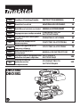
Makita DBO380 Cordless Finishing Sander Manual de utilizare
- Tip
- Manual de utilizare

DBO380
DBO381
EN Cordless Finishing Sander INSTRUCTION MANUAL 8
SL Brezžični brusilnik NAVODILA ZA UPORABO 19
SQ Rektikues lustrimi me bateri MANUALI I PËRDORIMIT 30
BG Акумулаторен виброшлайф РЪКОВОДСТВО ЗА
ЕКСПЛОАТАЦИЯ 41
HR Akumulatorska vibracijska
brusilica PRIRUČNIK S UPUTAMA 53
МК Безжична шмиргла за
финиширање УПАТСТВО ЗА УПОТРЕБА 64
SR Бежична брусилица за
завршну обраду УПУТСТВО ЗА УПОТРЕБУ 76
RO Mașină de șlefuit cu
acumulator MANUAL DE INSTRUCŢIUNI 88
UK Акумуляторна шліфувальна
машина кінцевої обробки ІНСТРУКЦІЯ З
ЕКСПЛУАТАЦІЇ 100
RU Аккумуляторная
вибрационная
шлифмашина
РУКОВОДСТВО ПО
ЭКСПЛУАТАЦИИ 112

1
2
3
Fig.1
1
2
Fig.2
1
2
3
Fig.3
1
Fig.4
12
35
4
1
4
52
3
Fig.5
1
2
3
Fig.6
2

1
2
3
4
5
1
2 3
4
5
Fig.7
1
2
Fig.8
1
2
3
4
5
1
2 3
4
5
Fig.9
1
2
3
3
5
4
5
4
Fig.10
1
1
2
3
Fig.11
3

1
2
3
Fig.12
1
23
Fig.13
12
3
Fig.14
12
3
Fig.15
1
2
3
3
Fig.16
15
2
3
4
Fig.17
15
2
3
4
Fig.18
4

1
2
3
3
Fig.19
12
34
Fig.20
12
3
4
Fig.21
Fig.22
Fig.23
Fig.24
1
Fig.25
5

1
2
3
4
Fig.26
1
2
3
Fig.27
1
Fig.28
12
1
2
Fig.29
Fig.30
1
Fig.31
6

1
2
Fig.32
1
Fig.33
1
Fig.34
12
1
2
Fig.35
7

8ENGLISH
ENGLISH (Original instructions)
SPECIFICATIONS
Model: DBO380 DBO381
Pad size 92 mm x 185 mm
Abrasive paper size 93 mm x 228 mm
Orbits per minute High 12,000 min-1
Medium 8,000 min-1
Low 4,000 min-1
Overall length (with front grip) 336 mm
Rated voltage D.C. 18 V
Net weight 1.9 - 2.2 kg
•
Due to our continuing program of research and development, the specications herein are subject to change without notice.
• Specications and battery cartridge may dier from country to country.
• The weight may dier depending on the attachment(s), including the battery cartridge. The lightest and heavi-
est combinations, according to EPTA-Procedure 01/2014, are shown in the table.
Applicable battery cartridge and charger
Battery cartridge BL1815N / BL1820B / BL1830B / BL1840B / BL1850B / BL1860B
Charger DC18RC / DC18RD / DC18RE / DC18SD / DC18SE / DC18SF /
DC18SH
•
Some of the battery cartridges and chargers listed above may not be available depending on your region of residence.
WARNING: Only use the battery cartridges and chargers listed above. Use of any other battery cartridges
and chargers may cause injury and/or re.
Intended use
The tool is intended for the sanding of large surface of
wood, plastic and metal materials as well as painted
surfaces.
Noise
The typical A-weighted noise level determined accord-
ing to EN62841-2-4:
Model DBO380
Sound pressure level (LpA) : 72 dB(A)
Uncertainty (K) : 3 dB(A)
Model DBO381
Sound pressure level (LpA) : 72 dB(A)
Uncertainty (K) : 3 dB(A)
The noise level under working may exceed 80 dB (A).
NOTE: The declared noise emission value(s) has
been measured in accordance with a standard test
method and may be used for comparing one tool with
another.
NOTE: The declared noise emission value(s)
may also be used in a preliminary assessment of
exposure.
WARNING: Wear ear protection.
WARNING:
The noise emission during actual
use of the power tool can dier from the declared
value(s) depending on the ways in which the tool is
used especially what kind of workpiece is processed.
WARNING:
Be sure to identify safety measures
to protect the operator that are based on an estima-
tion of exposure in the actual conditions of use (tak-
ing account of all parts of the operating cycle such
as the times when the tool is switched o and when
it is running idle in addition to the trigger time).
Vibration
The vibration total value (tri-axial vector sum) deter-
mined according to EN62841-2-4:
Model DBO380
Work mode: sanding metal plate
Vibration emission (ah) : 3.6 m/s2
Uncertainty (K) : 1.5 m/s2
Model DBO381
Work mode: sanding metal plate
Vibration emission (ah) : 3.6 m/s2
Uncertainty (K) : 1.5 m/s2
NOTE: The declared vibration total value(s) has been
measured in accordance with a standard test method
and may be used for comparing one tool with another.
NOTE: The declared vibration total value(s) may also
be used in a preliminary assessment of exposure.

9ENGLISH
WARNING:
The vibration emission during actual
use of the power tool can dier from the declared val-
ue(s) depending on the ways in which the tool is used
especially what kind of workpiece is processed.
WARNING:
Be sure to identify safety measures
to protect the operator that are based on an estima-
tion of exposure in the actual conditions of use (tak-
ing account of all parts of the operating cycle such
as the times when the tool is switched o and when
it is running idle in addition to the trigger time).
EC Declaration of Conformity
For European countries only
The EC declaration of conformity is included as Annex A
to this instruction manual.
SAFETY WARNINGS
General power tool safety warnings
WARNING: Read all safety warnings, instruc-
tions, illustrations and specications provided
with this power tool. Failure to follow all instructions
listed below may result in electric shock, re and/or
serious injury.
Save all warnings and instruc-
tions for future reference.
The term "power tool" in the warnings refers to your
mains-operated (corded) power tool or battery-operated
(cordless) power tool.
Sander safety warnings
1.
Always use safety glasses or goggles. Ordinary
eye or sun glasses are NOT safety glasses.
2. Hold the tool rmly.
3. Do not leave the tool running. Operate the tool
only when hand-held.
4. This tool has not been waterproofed, so do not
use water on the workpiece surface.
5. Ventilate your work area adequately when you
perform sanding operations.
6. Some material contains chemicals which may
be toxic. Take caution to prevent dust inhala-
tion and skin contact. Follow material supplier
safety data.
7. Use of this tool to sand some products, paints
and wood could expose user to dust contain-
ing hazardous substances. Use appropriate
respiratory protection.
8. Be sure that there are no cracks or breakage
on the pad before use. Cracks or breakage
may cause a personal injury.
9. Watch your footing and maintain your balance
with the tool. Make sure there is no one below
when working in high locations.
SAVE THESE INSTRUCTIONS.
WARNING: DO NOT let comfort or familiarity
with product (gained from repeated use) replace
strict adherence to safety rules for the subject
product. MISUSE or failure to follow the safety
rules stated in this instruction manual may cause
serious personal injury.
Important safety instructions for
battery cartridge
1. Before using battery cartridge, read all instruc-
tions and cautionary markings on (1) battery
charger, (2) battery, and (3) product using
battery.
2. Do not disassemble or tamper with the battery
cartridge. It may result in a re, excessive heat,
or explosion.
3. If operating time has become excessively
shorter, stop operating immediately. It may
result in a risk of overheating, possible burns
and even an explosion.
4. If electrolyte gets into your eyes, rinse them
out with clear water and seek medical atten-
tion right away. It may result in loss of your
eyesight.
5. Do not short the battery cartridge:
(1) Do not touch the terminals with any con-
ductive material.
(2) Avoid storing battery cartridge in a con-
tainer with other metal objects such as
nails, coins, etc.
(3) Do not expose battery cartridge to water
or rain.
A battery short can cause a large current
ow, overheating, possible burns and even a
breakdown.
6. Do not store and use the tool and battery car-
tridge in locations where the temperature may
reach or exceed 50 °C (122 °F).
7. Do not incinerate the battery cartridge even if
it is severely damaged or is completely worn
out. The battery cartridge can explode in a re.
8. Do not nail, cut, crush, throw, drop the battery
cartridge, or hit against a hard object to the
battery cartridge. Such conduct may result in a
re, excessive heat, or explosion.
9. Do not use a damaged battery.
10. The contained lithium-ion batteries are subject
to the Dangerous Goods Legislation require-
ments.
For commercial transports e.g. by third parties,
forwarding agents, special requirement on pack-
aging and labeling must be observed.
For preparation of the item being shipped, consult-
ing an expert for hazardous material is required.
Please also observe possibly more detailed
national regulations.
Tape or mask o open contacts and pack up the
battery in such a manner that it cannot move
around in the packaging.
11. When disposing the battery cartridge, remove
it from the tool and dispose of it in a safe
place. Follow your local regulations relating to
disposal of battery.

10 ENGLISH
12. Use the batteries only with the products
specied by Makita. Installing the batteries to
non-compliant products may result in a re, exces-
sive heat, explosion, or leak of electrolyte.
13. If the tool is not used for a long period of time,
the battery must be removed from the tool.
14. During and after use, the battery cartridge may
take on heat which can cause burns or low
temperature burns. Pay attention to the han-
dling of hot battery cartridges.
15. Do not touch the terminal of the tool imme-
diately after use as it may get hot enough to
cause burns.
16. Do not allow chips, dust, or soil stuck into the
terminals, holes, and grooves of the battery
cartridge. It may result in poor performance or
breakdown of the tool or battery cartridge.
17. Unless the tool supports the use near
high-voltage electrical power lines, do not use
the battery cartridge near high-voltage electri-
cal power lines. It may result in a malfunction or
breakdown of the tool or battery cartridge.
18. Keep the battery away from children.
SAVE THESE INSTRUCTIONS.
CAUTION: Only use genuine Makita batteries.
Use of non-genuine Makita batteries, or batteries that
have been altered, may result in the battery bursting
causing res, personal injury and damage. It will
also void the Makita warranty for the Makita tool and
charger.
Tips for maintaining maximum
battery life
1. Charge the battery cartridge before completely
discharged. Always stop tool operation and
charge the battery cartridge when you notice
less tool power.
2. Never recharge a fully charged battery car-
tridge. Overcharging shortens the battery
service life.
3. Charge the battery cartridge with room tem-
perature at 10 °C - 40 °C (50 °F - 104 °F). Let
a hot battery cartridge cool down before
charging it.
4. When not using the battery cartridge, remove
it from the tool or the charger.
5. Charge the battery cartridge if you do not use
it for a long period (more than six months).
Important safety instructions for
wireless unit
1. Do not disassemble or tamper with the wire-
less unit.
2. Keep the wireless unit away from young chil-
dren. If accidentally swallowed, seek medical
attention immediately.
3. Use the wireless unit only with Makita tools.
4. Do not expose the wireless unit to rain or wet
conditions.
5. Do not use the wireless unit in places where
the temperature exceeds 50 °C (122 °F).
6. Do not operate the wireless unit in places
where medical instruments, such as heart
pace makers are nearby.
7. Do not operate the wireless unit in places
where automated devices are nearby. If oper-
ated, automated devices may develop malfunction
or error.
8. Do not operate the wireless unit in places
under high temperature or places where
static electricity or electrical noise could be
generated.
9.
The wireless unit can produce electromagnetic
elds (EMF) but they are not harmful to the user.
10. The wireless unit is an accurate instrument. Be
careful not to drop or strike the wireless unit.
11. Avoid touching the terminal of the wireless
unit with bare hands or metallic materials.
12. Always remove the battery on the product
when installing the wireless unit into it.
13. When opening the lid of the slot, avoid the
place where dust and water may come into the
slot. Always keep the inlet of the slot clean.
14. Always insert the wireless unit in the correct
direction.
15. Do not press the wireless activation button
on the wireless unit too hard and/or press the
button with an object with a sharp edge.
16. Always close the lid of the slot when
operating.
17. Do not remove the wireless unit from the slot
while the power is being supplied to the tool.
Doing so may cause a malfunction of the wireless
unit.
18. Do not remove the sticker on the wireless unit.
19. Do not put any sticker on the wireless unit.
20. Do not leave the wireless unit in a place where
static electricity or electrical noise could be
generated.
21. Do not leave the wireless unit in a place sub-
ject to high heat, such as a car sitting in the
sun.
22. Do not leave the wireless unit in a dusty or
powdery place or in a place corrosive gas
could be generated.
23. Sudden change of the temperature may bedew
the wireless unit. Do not use the wireless unit
until the dew is completely dried.
24. When cleaning the wireless unit, gently wipe
with a dry soft cloth. Do not use benzine, thin-
ner, conductive grease or the like.
25. When storing the wireless unit, keep it in the
supplied case or a static-free container.
26. Do not insert any devices other than Makita
wireless unit into the slot on the tool.
27. Do not use the tool with the lid of the slot dam-
aged. Water, dust, and dirt come into the slot may
cause malfunction.
28. Do not pull and/or twist the lid of the slot more
than necessary. Restore the lid if it comes o
from the tool.
29. Replace the lid of the slot if it is lost or
damaged.
SAVE THESE INSTRUCTIONS.

11 ENGLISH
FUNCTIONAL
DESCRIPTION
CAUTION: Always be sure that the tool is
switched o and the battery cartridge is removed
before adjusting or checking function on the tool.
Installing or removing battery
cartridge
CAUTION: Always switch o the tool before
installing or removing of the battery cartridge.
CAUTION: Hold the tool and the battery car-
tridge rmly when installing or removing battery
cartridge. Failure to hold the tool and the battery
cartridge rmly may cause them to slip o your hands
and result in damage to the tool and battery cartridge
and a personal injury.
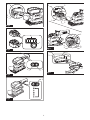
► Fig.1: 1. Red indicator 2. Button 3. Battery cartridge
To remove the battery cartridge, slide it from the tool
while sliding the button on the front of the cartridge.
To install the battery cartridge, align the tongue on the
battery cartridge with the groove in the housing and slip
it into place. Insert it all the way until it locks in place
with a little click. If you can see the red indicator as
shown in the gure, it is not locked completely.
CAUTION: Always install the battery cartridge
fully until the red indicator cannot be seen. If not,
it may accidentally fall out of the tool, causing injury to
you or someone around you.
CAUTION: Do not install the battery cartridge
forcibly. If the cartridge does not slide in easily, it is
not being inserted correctly.
Battery protector
Use a battery protector supplied with the tool to safe-
guard and shield the battery cartridge.
CAUTION: Always remove the battery car-
tridge from the tool before installing and unin-
stalling a battery protector.
CAUTION: Never hand hold a battery pro-
tector when carrying the tool from one area to
another or when holding the tool while not in use.
NOTICE: A battery protector can only be
installed in among battery models BL1830B /
BL1840B / BL1850B / BL1860B.
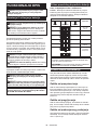
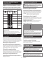
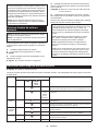
Indicating the remaining battery
capacity
Only for battery cartridges with the indicator
► Fig.2: 1. Indicator lamps 2. Check button
Press the check button on the battery cartridge to indi-
cate the remaining battery capacity. The indicator lamps
light up for a few seconds.
Indicator lamps Remaining
capacity
Lighted O Blinking
75% to 100%
50% to 75%
25% to 50%
0% to 25%
Charge the
battery.
The battery
may have
malfunctioned.
NOTE: Depending on the conditions of use and the
ambient temperature, the indication may dier slightly
from the actual capacity.
NOTE: The rst (far left) indicator lamp will blink when
the battery protection system works.
Tool / battery protection system
The tool is equipped with a tool/battery protection sys-
tem. This system automatically cuts o power to the
motor to extend tool and battery life. The tool will auto-
matically stop during operation if the tool or battery is
placed under one of the following conditions:
Overload protection
When the tool or battery is operated in a manner that
causes it to draw an abnormally high current, the tool
automatically stops without any indication. In this sit-
uation, turn the tool o and stop the application that
caused the tool to become overloaded. Then turn the
tool on to restart.
Overheat protection
When the tool or battery is overheated, the tool stops
automatically. In this case, let the tool and battery cool
before turning the tool on again.
Overdischarge protection
When the battery capacity is not enough, the tool stops
automatically. In this case, remove the battery from the
tool and charge the battery.

12 ENGLISH
Switch action
CAUTION: Avoid turning the tool on while it
is placed on the workpiece or on your workbench.
It may cause personal injury or damage.
Turning the tool on and o
Press the power/speed select button on the top of the
main handle to start the tool. The tool starts to run at its
highest orbital speed.
Press the stop button to pause or cease operation.
► Fig.3: 1. Power/speed select button 2. Stop button
3. Main handle
Changing the tool speed
The orbital speed can be changed in three modes, that is, high,
medium and low depending on the application and workload.
Press the power/speed select button to switch speed mode.
► Fig.4: 1. Power/speed select button
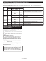
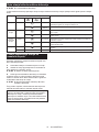
Speed settings table
Speed level Orbital per minute
3 (High) 12,000 min-1 (/min)
2 (Medium) 8,000 min-1 (/min)
1 (Low) 4,000 min-1 (/min)
NOTICE: If the tool is operated continuously
at low speeds for a long time, the motor will get
overloaded, resulting in tool malfunction.
NOTICE: Select an appropriate speed range for
your sanding operations to avoid overheating
and melting the workpiece. Sanding at high orbital
speed may heat workpiece and melt it at the point of
contact.
Electronic function
The tool is equipped with the electronic function for easy operation.
Constant speed control
This function serves a constant orbital speed to obtain
ne nish.
ASSEMBLY
CAUTION: Always be sure that the tool is
switched o and the battery cartridge is removed
before carrying out any work on the tool.
Installing and removing abrasive
paper
CAUTION: Always make sure that a sheet of
abrasive paper is installed securely before use.
The paper may otherwise be loosened, removed
easily and subject to slippage, resulting in uneven
sanding operation.
Using abrasive paper supplied with tool
1. Push and hold down the clamp lever on either
front or rear end of the pad, and slide it away from the
stopper so the clamp is released from its fastened
position.
2. Pull the clamp lever outwards as far as possible to
create a space between the clamp and side wall of the
sanding base in which one end of abrasive paper can
be inserted.
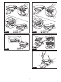
► Fig.5: 1. Clamp lever 2. Stopper 3. Clamp
4. Sanding base 5. Pad
3.
Place a sheet of abrasive paper over the pad, aligning
the dust-suction holes in the paper with those in the pad.
► Fig.6: 1. Abrasive paper 2. Pad 3. Dust-suction hole
4. Slip one end of the abrasive paper into the space
between the clamp and sanding base.
5. Set the clamp lever back in a locked position so
the end of abrasive paper is clamped securely.
6. Release the clamp on the other end, and have the
other end of abrasive paper ready to be clamped.
7. Maintain a proper tension on abrasive paper, and
then set the clamp lever on the other end in a locked
position.
► Fig.7: 1. Abrasive paper 2. Clamp 3. Sanding base
4. Clamp lever 5. Stopper
8. To remove the abrasive paper, release the clamps
on both ends and take the paper o the pad.
Using abrasive paper available in the market
1. Cut a sheet of abrasive paper down to an appro-
priate size.
► Fig.8: 1. Abrasive paper 2. Pad
2. Push and hold down the clamp lever on either
front or rear end of the pad, and slide it away from the
stopper so the clamp is released from its fastened
position.
3. Pull the clamp lever outwards as far as possible to
create a space between the clamp and side wall of the
sanding base in which one end of abrasive paper can
be inserted.
4. Slip one end of the abrasive paper into the space
between the clamp and sanding base.
5. Reposition the abrasive paper so it is nely over-
laid on the pad surface.
6. Set the clamp lever back in a locked position to
clamp the end of abrasive paper securely.
7. Release the clamp on the other end, and have the
other end of abrasive paper ready to be clamped.
8.
Maintain a proper tension on abrasive paper, and then
set the clamp lever on the other end in a locked position.
► Fig.9: 1. Abrasive paper 2. Clamp 3. Sanding base
4. Clamp lever 5. Stopper
9. Cover the abrasive paper with the punch plate
with its positioning stoppers adjacent to the corner well
t onto two of the side edges of the pad and sanding
base.
► Fig.10: 1. Abrasive paper 2. Punch plate
3. Positioning stoppers 4. Pad 5. Sanding
base

13 ENGLISH
10. Push the punch plate over the abrasive paper to
make dust-suction holes.
11. To remove the abrasive paper, release the clamps
on both ends and take the paper o the pad.
Using hook-and-loop abrasive paper
Optional accessory
CAUTION: Make sure to install a hook-and-
loop pad correctly and securely. A loose attach-
ment will run out of balance and cause an excessive
vibration resulting in loss of control.
CAUTION: Be sure that a hook-and-loop pad
and abrasive paper are aligned and securely
attached.
CAUTION: Only use hook-and-loop abrasive
papers. Never use pressure-sensitive abrasive
papers.
1. Loosen and remove the four screws securing the
pad to the sanding base.
2. Replace the standard-equipped pad with an
optional hook-and-loop pad.
3. Re-tighten the screws rmly to secure the hook-
and-loop pad.
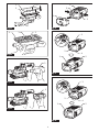
► Fig.11: 1. Screws 2. Sanding base 3. Pad
4. Remove all dirt and foreign matter from the hook-
and-loop pad.
5. Attach a sheet of optional hook-and-loop abrasive
paper to the pad, aligning the dust-suction holes in the
paper with those in the pad.
► Fig.12: 1. Abrasive paper 2. Pad 3. Dust-suction
holes
6. To remove the abrasive paper, peel it o from the
edge.
CAUTION: The O ring may come out of the
sanding base while replacing the pad. Set the O
ring back in the circular grooves around the cen-
ter of the base before installing the optional pad.
► Fig.13: 1. O ring 2. Sanding base 3. Circular
grooves
Installing and removing dust bag
Optional accessory
Attach the dust bag over the tapered dust spout at the
back end of the motor housing. Put the dust inlet of the
bag onto the dust spout as far as it will go to avoid it
from coming o during operation.
► Fig.14: 1. Dust spout 2. Dust inlet 3. Dust bag
NOTE: Make sure to attach the dust bag with its
zipper slider facing downwards.
NOTE: To ensure optimal dust collecting, empty the
dust bag when it becomes lled to approximately half
of its capacity.
Remove the dust bag from the tool and pull the fas-
tener out. Then gently shake or tap the dust bag to
empty.
Installing and removing dust box
Optional accessory
Attach the dust box over the tapered dust spout at the
back end of the motor housing. Put the dust nozzle onto
the dust spout as far as it will go to avoid it from coming
o during operation.
► Fig.15: 1. Dust spout 2. Dust nozzle 3. Dust box
NOTE: To ensure optimal dust collecting, empty the
dust box when it becomes lled to approximately half
of its capacity.
1. Remove the dust box from the tool.
2. Detach the dust nozzle from the box while
pressing and holding the locking latches on both
sides of the box.
3. Gently shake or tap the dust box to empty.
Replacing lter
NOTICE: Be aware to align the logos on all the
dust box, lter and dust nozzle in a consistent
orientation when reassembling components.
1. Remove the dust box from the tool.
2. Detach the dust nozzle from the box while press-
ing and holding the locking latches on both sides of the
box.
► Fig.16: 1. Dust nozzle 2. Dust box 3. Locking latch
3. Hold the inner top edge of the cardboard opening,
and pull it o downwards to disengage the outer top
edge of the cardboard opening from the upper hooking
tab on the lip of the dust box.
4. Take the lter out of the dust box while pulling the
outer bottom edge of the cardboard opening free from
the lower hooking tab.
► Fig.17: 1. Filter 2. Cardboard opening 3. Upper
hooking tab 4. Lower hooking tab 5. Dust
box
5. Replace a lter by engaging the bottom edge of
the cardboard opening in the lower hooking tab and
push the top edge inwards until it clips into the upper
hooking tab .
► Fig.18: 1. Filter 2. Cardboard opening 3. Upper
hooking tab 4. Lower hooking tab 5. Dust
box
6. Snap the dust nozzle into place while pressing
and holding the locking latches on both sides of the dust
box.
► Fig.19: 1. Dust nozzle 2. Dust box 3. Locking latch
Removing and installing front grip
CAUTION: After reassembly, pull the front
grip to check if it is securely attached together.
NOTICE: Make sure to push the front grip fully
into the slot end and keep it positioned where it is
while rotating the front grip. Failure to do so may
cause damage to the tool.

14 ENGLISH
By removing the detachable front grip, sanding opera-
tion in tight, conned and hard-to-reach areas can be
performed eectively.
Uninstallation
Push and hold the front grip rmly towards the motor
housing and rotate it 90 degrees to either the left or
right. Then pull it apart from the tool.
Installation
Insert the end of the front grip into the slot on the motor hous-
ing, aligning the outlines of the grip end with those of the slot.
Push and hold the front grip rmly towards the housing
and rotate it 90 degrees with its gripping surface facing
upwards.
► Fig.20: 1. Front grip 2. Slot 3. Motor housing
4. Gripping surface
Connecting with vacuum cleaner
Optional accessory
When you wish to perform clean sanding operation,
connect a Makita vacuum cleaner to your tool. Use
either an optional horse 28 mm or a combination of front
cus 22 and hose provided with the cleaner to establish
a connection.
► Fig.21: 1. Dust spout 2. Front cus 3. Hose
4. Vacuum cleaner
OPERATION
Sanding operation
CAUTION: Never run the tool without the
abrasive paper. You may seriously damage the pad.
CAUTION: Never force the tool. Excessive
pressure may decrease the sanding eciency, dam-
age the abrasive paper and/or shorten tool life.
Sanding open areas
1. Hold the tool rmly with your both hands, one
hand on the handle and the other on the front grip.
2. Turn the tool on and wait until it attains full speed.
3. Gently place the tool on the workpiece surface.
4. Keep the entire pad level and even with the sur-
face and apply slight pressure on the tool.
► Fig.22
Sanding conned areas
1. Detach the front grip from the tool.
2. Hold the handle with one hand.
3. Turn the tool on and wait until it attains full speed.
4. Gently place the tool on the workpiece surface.
5. Keep the entire pad level and even with the sur-
face and apply slight pressure on the tool.
6. Move the tool along curves, wall faces and in other
conned spaces, sanding with the front and corner
edges of the pad as you need.
► Fig.23
WIRELESS ACTIVATION
FUNCTION
For model DBO381 only
NOTICE: The wireless function is only available
when the supported vacuum cleaner is being
installed.
What you can do with the wireless
activation function
The wireless activation function enables clean and com-
fortable operation. By connecting a supported vacuum
cleaner to the tool, you can run the vacuum cleaner
automatically along with the switch operation of the tool.
► Fig.24
To use the wireless activation function, prepare follow-
ing items:
• A wireless unit (optional accessory)
• A vacuum cleaner which supports the wireless
activation function
The overview of the wireless activation function
setting is as follows. Refer to each section for detail
procedures.
1. Installing the wireless unit
2. Tool registration for the vacuum cleaner
3. Starting the wireless activation function
Installing the wireless unit
Optional accessory
CAUTION: Place the tool on a at and stable
surface when installing the wireless unit.
NOTICE: Clean the dust and dirt on the tool
before installing the wireless unit. Dust or dirt
may cause malfunction if it comes into the slot of the
wireless unit.
NOTICE: To prevent the malfunction caused by
static, touch a static discharging material, such
as a metal part of the tool, before picking up the
wireless unit.
NOTICE: When installing the wireless unit,
always be sure that the wireless unit is inserted
in the correct direction and the lid is completely
closed.
1. Open the lid on the tool as shown in the gure.
► Fig.25: 1. Lid
2. Insert the wireless unit to the slot and then close
the lid.
When inserting the wireless unit, align the projections
with the recessed portions on the slot.
► Fig.26: 1. Wireless unit 2. Projection 3. Lid
4. Recessed portion

15 ENGLISH
When removing the wireless unit, open the lid slowly.
The hooks on the back of the lid will lift the wireless unit
as you pull up the lid.
► Fig.27: 1. Wireless unit 2. Hook 3. Lid
After removing the wireless unit, keep it in the supplied
case or a static-free container.
NOTICE: Always use the hooks on the back of
the lid when removing the wireless unit. If the
hooks do not catch the wireless unit, close the lid
completely and open it slowly again.
Tool registration for the vacuum
cleaner
NOTE: A Makita vacuum cleaner supporting the
wireless activation function is required for the tool
registration.
NOTE: Finish installing the wireless unit to the tool
before starting the tool registration.
NOTE: During the tool registration, do not pull the
switch trigger or turn on the power switch on the
vacuum cleaner.
NOTE: Refer to the instruction manual of the vacuum
cleaner, too.
If you wish to activate the vacuum cleaner along with
the switch operation of the tool, nish the tool registra-
tion beforehand.
1. Install the batteries to the vacuum cleaner and the
tool.
2. Set the stand-by switch on the vacuum cleaner to
"AUTO".
► Fig.28: 1. Stand-by switch
3. Press the wireless activation button on the vac-
uum cleaner for 3 seconds until the wireless activation
lamp blinks in green. And then press the wireless acti-
vation button on the tool in the same way.
► Fig.29: 1. Wireless activation button 2. Wireless
activation lamp
If the vacuum cleaner and the tool are linked success-
fully, the wireless activation lamps will light up in green
for 2 seconds and start blinking in blue.
NOTE: The wireless activation lamps nish blinking
in green after 20 seconds elapsed. Press the wireless
activation button on the tool while the wireless acti-
vation lamp on the cleaner is blinking. If the wireless
activation lamp does not blink in green, push the wire-
less activation button briey and hold it down again.
NOTE: When performing two or more tool registra-
tions for one vacuum cleaner, nish the tool registra-
tion one by one.
Starting the wireless activation
function
NOTE: Finish the tool registration for the vacuum
cleaner prior to the wireless activation.
NOTE: Refer to the instruction manual of the vacuum
cleaner, too.
After registering a tool to the vacuum cleaner, the
vacuum cleaner will automatically runs along with the
switch operation of the tool.
1. Install the wireless unit to the tool.
2. Connect the hose of the vacuum cleaner with the
tool.
► Fig.30
3. Set the stand-by switch on the vacuum cleaner to
"AUTO".
► Fig.31: 1. Stand-by switch
4. Push the wireless activation button on the tool
briey. The wireless activation lamp will blink in blue.
► Fig.32: 1. Wireless activation button 2. Wireless
activation lamp
5. Pull the switch trigger of the tool. Check if the
vacuum cleaner runs while the switch trigger is being
pulled.
To stop the wireless activation of the vacuum cleaner,
push the wireless activation button on the tool.
NOTE: The wireless activation lamp on the tool will
stop blinking in blue when there is no operation for
2 hours. In this case, set the stand-by switch on the
vacuum cleaner to "AUTO" and push the wireless
activation button on the tool again.
NOTE: The vacuum cleaner starts/stops with a delay.
There is a time lag when the vacuum cleaner detects
a switch operation of the tool.
NOTE: The transmission distance of the wireless unit
may vary depending on the location and surrounding
circumstances.
NOTE: When two or more tools are registered to one
vacuum cleaner, the vacuum cleaner may start run-
ning even if you do not pull the switch trigger because
another user is using the wireless activation function.

16 ENGLISH
Description of the wireless activation lamp status
► Fig.33: 1. Wireless activation lamp
The wireless activation lamp shows the status of the wireless activation function. Refer to the table below for the
meaning of the lamp status.
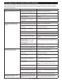
Status Wireless activation lamp Description
Color
On
Blinking
Duration
Standby Blue 2 hours The wireless activation of the vacuum cleaner is available. The
lamp will automatically turn o when no operation is performed
for 2 hours.
When
the tool is
running.
The wireless activation of the vacuum cleaner is available and the
tool is running.
Tool
registration Green 20 seconds Ready for the tool registration. Waiting for the registration by the
vacuum cleaner.
2 seconds The tool registration has been nished. The wireless activation
lamp will start blinking in blue.
Cancelling
tool
registration
Red 20 seconds Ready for the cancellation of the tool registration. Waiting for the
cancellation by the vacuum cleaner.
2 seconds The cancellation of the tool registration has been nished. The
wireless activation lamp will start blinking in blue.
Others Red 3 seconds The power is supplied to the wireless unit and the wireless activa-
tion function is starting up.
O - - The wireless activation of the vacuum cleaner is stopped.
Cancelling tool registration for the
vacuum cleaner
Perform the following procedure when cancelling the
tool registration for the vacuum cleaner.
1. Install the batteries to the vacuum cleaner and the
tool.
2. Set the stand-by switch on the vacuum cleaner to
"AUTO".
► Fig.34: 1. Stand-by switch
3. Press the wireless activation button on the vac-
uum cleaner for 6 seconds. The wireless activation
lamp blinks in green and then become red. After that,
press the wireless activation button on the tool in the
same way.
► Fig.35: 1. Wireless activation button 2. Wireless
activation lamp
If the cancellation is performed successfully, the wire-
less activation lamps will light up in red for 2 seconds
and start blinking in blue.
NOTE: The wireless activation lamps nish blinking in
red after 20 seconds elapsed. Press the wireless acti-
vation button on the tool while the wireless activation
lamp on the cleaner is blinking. If the wireless acti-
vation lamp does not blink in red, push the wireless
activation button briey and hold it down again.

17 ENGLISH
Troubleshooting for wireless activation function
Before asking for repairs, conduct your own inspection rst. If you nd a problem that is not explained in the manual,
do not attempt to dismantle the tool. Instead, ask Makita Authorized Service Centers, always using Makita replace-
ment parts for repairs.
State of abnormality Probable cause (malfunction) Remedy
The wireless activation lamp does
not light/blink.
The wireless unit is not installed into the tool.
The wireless unit is improperly installed
into the tool.
Install the wireless unit correctly.
The terminal of the wireless unit and/or
the slot is dirty. Gently wipe o dust and dirt on the terminal of the
wireless unit and clean the slot.
The wireless activation button on the
tool has not been pushed. Push the wireless activation button on the tool
briey.
The stand-by switch on the vacuum
cleaner is not set to "AUTO". Set the stand-by switch on the vacuum cleaner to
"AUTO".
No power supply
Supply the power to the tool and the vacuum cleaner.
Cannot nish tool registration / can-
celling tool registration successfully.
The wireless unit is not installed into the tool.
The wireless unit is improperly installed
into the tool.
Install the wireless unit correctly.
The terminal of the wireless unit and/or
the slot is dirty. Gently wipe o dust and dirt on the terminal of the
wireless unit and clean the slot.
The stand-by switch on the vacuum
cleaner is not set to "AUTO". Set the stand-by switch on the vacuum cleaner to
"AUTO".
No power supply
Supply the power to the tool and the vacuum cleaner.
Incorrect operation
Push the wireless activation button briey and perform
the tool registration/cancellation procedures again.
The tool and vacuum cleaner are away
from each other (out of the transmission
range).
Get the tool and vacuum cleaner closer to each other. The
maximum transmission distance is approximately 10 m
however it may vary according to the circumstances.
Before nishing the tool registration/cancellation;
- the switch trigger on the tool is pulled or;
- the power button on the vacuum
cleaner is turned on.
Push the wireless activation button briey and
perform the tool registration/cancellation procedures
again.
The tool registration procedures for the
tool or vacuum cleaner have not nished.
Perform the tool registration procedures for both the
tool and the vacuum cleaner at the same timing.
Radio disturbance by other appliances
which generate high-intensity radio
waves.
Keep the tool and vacuum cleaner away from the
appliances such as Wi-Fi devices and microwave
ovens.
The vacuum cleaner does not run
along with the switch operation of
the tool.
The wireless unit is not installed into the tool.
The wireless unit is improperly installed
into the tool.
Install the wireless unit correctly.
The terminal of the wireless unit and/or
the slot is dirty. Gently wipe o dust and dirt on the terminal of the
wireless unit and clean the slot.
The wireless activation button on the
tool has not been pushed.
Push the wireless activation button briey and make
sure that the wireless activation lamp is blinking in blue.
The stand-by switch on the vacuum
cleaner is not set to "AUTO". Set the stand-by switch on the vacuum cleaner to
"AUTO".
More than 10 tools are registered to the
vacuum cleaner.
Perform the tool registration again.
If more than 10 tools are registered to the vacuum cleaner,
the tool registered earliest will be cancelled automatically.
The vacuum cleaner erased all tool
registrations. Perform the tool registration again.
No power supply
Supply the power to the tool and the vacuum cleaner.
The tool and vacuum cleaner are away
from each other (out of the transmission
range).
Get the tool and vacuum cleaner closer each other.
The maximum transmission distance is approxi-
mately 10 m however it may vary according to the
circumstances.
Radio disturbance by other appliances
which generate high-intensity radio
waves.
Keep the tool and vacuum cleaner away from the
appliances such as Wi-Fi devices and microwave
ovens.
The vacuum cleaner runs while the
tool's switch trigger is not pulled. Other users are using the wireless
activation of the vacuum cleaner with
their tools.
Turn o the wireless activation button of the other
tools or cancel the tool registration of the other
tools.

18 ENGLISH
MAINTENANCE
CAUTION: Always be sure that the tool is
switched o and the battery cartridge is removed
before attempting to perform inspection or
maintenance.
NOTICE: Never use gasoline, benzine, thinner,
alcohol or the like. Discoloration, deformation or
cracks may result.
To maintain product SAFETY and RELIABILITY,
repairs, any other maintenance or adjustment should
be performed by Makita Authorized or Factory Service
Centers, always using Makita replacement parts.
After use
Wipe o the tool using a dry cloth or cloth slightly moist-
ened with soapy water at regular intervals.
OPTIONAL
ACCESSORIES
CAUTION: These accessories or attachments
are recommended for use with your Makita tool
specied in this manual. The use of any other
accessories or attachments might present a risk of
injury to persons. Only use accessory or attachment
for its stated purpose.
If you need any assistance for more details regard-
ing these accessories, ask your local Makita Service
Center.
• Abrasive paper (with pre-punched holes)
• Hook-and-loop type of abrasive paper
• Punch plate
• Backing pad (For use with hook-and-loop type of
abrasive paper)
• Backing pad (For use with conventional type of
abrasive paper)
• Dust bag
• Dust box
• Filter
• Hose
• Wireless unit (for model DBO381)
• Battery protector
• Makita genuine battery and charger
NOTE: Some items in the list may be included in the
tool package as standard accessories. They may
dier from country to country.

19 SLOVENŠČINA
SLOVENŠČINA (Originalna navodila)
TEHNIČNI PODATKI
Model: DBO380 DBO381
Velikost podloge 92 mm x 185 mm
Velikost brusnega papirja 93 mm x 228 mm
Vrtljaji na minuto Hitro 12.000 min-1
Srednje 8.000 min-1
Počasi 4.000 min-1
Celotna dolžina (s sprednjim ročajem) 336 mm
Nazivna napetost D.C. 18 V
Neto teža 1,9 - 2,2 kg
•
Ker nenehno opravljamo raziskave in razvijamo svoje izdelke, se lahko tehnični podatki v tem dokumentu spremenijo brez obvestila.
• Tehnični podatki in baterijski vložki se lahko razlikujejo glede na državo uporabe izdelka.
• Teža se lahko razlikuje glede na priključke, vključno z akumulatorsko baterijo. Najlažja in najtežja kombinacija v
skladu s postopkom EPTA 01/2014 sta prikazani v preglednici.
Uporabna akumulatorska baterija in polnilnik
Baterijski vložek BL1815N / BL1820B / BL1830B / BL1840B / BL1850B / BL1860B
Polnilnik DC18RC / DC18RD / DC18RE / DC18SD / DC18SE / DC18SF /
DC18SH
• Nekatere zgoraj navedene akumulatorske baterije in polnilniki morda v vaši državi prebivališča niso na voljo.
OPOZORILO: Uporabljajte le zgoraj navedene akumulatorske baterije in polnilnike. Uporaba drugih
akumulatorskih baterij in polnilnikov lahko povzroči telesne poškodbe in/ali požar.
Predvidena uporaba
Orodje je namenjeno brušenju velikih lesenih površin,
plastike in kovinskih materialov ter lakiranih površin.
Hrup
Običajna A-ovrednotena raven hrupa v skladu z
EN62841-2-4:
Model DBO380
Raven zvočnega tlaka (LpA): 72 dB (A)
Odstopanje (K): 3 dB (A)
Model DBO381
Raven zvočnega tlaka (LpA): 72 dB (A)
Odstopanje (K): 3 dB (A)
Nivo hrupa med delom lahko preseže 80 dB (A).
OPOMBA: Navedene vrednosti oddajanja hrupa so
bile izmerjene v skladu s standardnimi metodami
testiranja in se lahko uporabljajo za primerjavo orodij.
OPOMBA: Navedene vrednosti oddajanja hrupa
se lahko uporabljajo tudi pri predhodni oceni
izpostavljenosti.
OPOZORILO: Uporabljajte zaščito za sluh.
OPOZORILO: Oddajanje hrupa med dejansko
uporabo električnega orodja se lahko razlikuje od
navedenih vrednosti, odvisno od načina uporabe
orodja in predvsem vrste obdelovanca.
OPOZORILO:
Upravljavec mora za lastno zaščito
poznati varnostne ukrepe, ki temeljijo na oceni izpostavlje-
nosti v dejanskih pogojih uporabe (poleg časa proženja je
treba upoštevati celoten delovni cikel, vključno s časom, ko
je orodje izklopljeno, in časom, ko deluje v prostem teku).
Vibracije
Skupne vrednosti vibracij (vektorska vsota treh osi) v
skladu z EN62841-2-4:
Model DBO380
Delovni način: brušenje kovinske plošče
Emisije vibracij (ah): 3,6 m/s2
Odstopanje (K): 1,5 m/s2
Model DBO381
Delovni način: brušenje kovinske plošče
Emisije vibracij (ah): 3,6 m/s2
Odstopanje (K): 1,5 m/s2
OPOMBA:
Navedene skupne vrednosti oddajanja vibra-
cij so bile izmerjene v skladu s standardnimi metodami
testiranja in se lahko uporabljajo za primerjavo orodij.
OPOMBA: Navedene skupne vrednosti oddajanja
vibracij se lahko uporabljajo tudi pri predhodni oceni
izpostavljenosti.

20 SLOVENŠČINA
OPOZORILO:
Oddajanje vibracij med dejansko
uporabo električnega orodja se lahko razlikuje od
navedenih vrednosti, odvisno od načina uporabe
orodja in predvsem vrste obdelovanca.
OPOZORILO:
Upravljavec mora za lastno zaščito
poznati varnostne ukrepe, ki temeljijo na oceni izpostavlje-
nosti v dejanskih pogojih uporabe (poleg časa proženja je
treba upoštevati celoten delovni cikel, vključno s časom, ko
je orodje izklopljeno, in časom, ko deluje v prostem teku).
Izjava o skladnosti ES
Samo za evropske države
Izjava ES o skladnosti je vključena v dodatku A, ki je
priložen tem navodilom za uporabo.
VARNOSTNA OPOZORILA
Splošna varnostna opozorila za
električno orodje
OPOZORILO: Preberite vsa varnostna opo-
zorila in navodila s slikami in tehničnimi podatki,
ki so dobavljeni skupaj z električnim orodjem.
Ob neupoštevanju spodaj navedenih navodil obstaja
nevarnost električnega udara, požara in/ali hudih
telesnih poškodb.
Shranite vsa opozorila in navo-
dila za poznejšo uporabo.
Izraz „električno orodje“ v opozorilih se nanaša na vaše
električno orodje (s kablom) ali baterijsko električno
orodje (brez kabla).
Varnostna opozorila za brusilnik
1. Vedno uporabljajte zaščitna očala. Navadna ali
sončna očala NISO zaščitna očala.
2. Trdno držite orodje.
3. Orodja ne pustite delovati brez nadzora.
Dovoljeno ga je uporabljati samo ročno.
4.
Za to orodje ni bila preverjena vodotesnost, zato
ne uporabljajte vode na površini obdelovanca.
5.
Med brušenjem dobro prezračite svoj delovni prostor.
6. Nekateri materiali vsebujejo kemikalije, ki so
lahko strupene. Bodite previdni ter preprečite
vdihavanje prahu in stik s kožo. Upoštevajte
varnostne podatke dobavitelja materiala.
7. Pri uporabi tega orodja za brušenje nekate-
rih izdelkov, barv in lesa je lahko uporabnik
izpostavljen prahu, ki vsebuje nevarne snovi.
Uporabljajte ustrezno zaščito dihal.
8. Pred uporabo se prepričajte, da na blazinici ni
razpok ali zlomljenih delov. Razpoke ali zlom-
ljeni deli lahko povzročijo telesne poškodbe.
9. Poskrbite za varno stojišče in pazite na stalno
ravnotežje telesa in orodja. Pri delu na visokih
mestih pazite, da pod vami ni nikogar.
SHRANITE TA NAVODILA.
OPOZORILO: NE dovolite, da bi zaradi udob-
nejšega dela ali znanja o uporabi izdelka (prido-
bljenega z večkratno uporabo) opustili strogo
upoštevanje varnostnih zahtev v okviru pravilne
uporabe orodja. ZLORABA ali neupoštevanje var-
nostnih zahtev v teh navodilih za uporabo lahko
povzroči resne telesne poškodbe.
Pomembna varnostna navodila za
akumulatorsko baterijo
1. Pred uporabo baterijskega vložka preberite
vsa navodila in opozorilne oznake na (1) pol-
nilniku akumulatorja, (2) akumulatorju in (3)
izdelku, ki uporablja akumulator.
2. Ne razstavljajte ali spreminjajte akumulatorske
baterije. S tem lahko povzročite požar, preko-
merno vročino ali eksplozijo.
3. Če se je čas delovanja občutno skrajšal, takoj
prenehajte uporabljati orodje. V nasprotnem
primeru lahko pride do pregretja, morebitnih
opeklin in celo eksplozije.
4. Če pride elektrolit v stik z očmi, jih sperite s
čisto vodo in takoj poiščite zdravniško pomoč.
Posledica je lahko izguba vida.
5.
Ne povzročite kratkega stika baterijskega vložka:
(1) Ne dotikajte se priključkov s kakršnim
koli prevodnim materialom.
(2) Izogibajte se shranjevanju baterijskega
vložka v vsebniku z drugimi kovinskimi
predmeti kot so žeblji, kovanci itn.
(3) Ne izpostavljajte baterijskega vložka vodi
ali dežju.
Kratek stik akumulatorja lahko povzroči velik
električni tok, pregrevanje, morebitne opekline
in celo okvaro.
6. Ne shranjujte in uporabljajte orodja in akumu-
latorske baterije na mestih, kjer lahko tempera-
tura doseže ali preseže 50 °C (122 °F).
7. Ne sežigajte baterijskega vložka, tudi če je
hudo poškodovan ali v celoti izpraznjen.
Baterijski vložek lahko v ognju eksplodira.
8. Ne pribijajte, režite, drobite, mečite, spuščajte
akumulatorske baterije oziroma ne udarjajte
z akumulatorsko baterijo po trdem predmetu.
Takšno ravnanje lahko povzroči požar, preko-
merno vročino ali eksplozijo.
9. Ne uporabljajte poškodovanih akumulatorjev.
10. Priložene litij-ionske baterije ustrezajo zahte-
vam zakonodaje v zvezi z nevarnim blagom.
Za komercialne prevoze, npr. tiste, ki jih opravljajo
tretje stranke in carinski posredniki, je treba upo-
števati posebne zahteve v zvezi z embalažo in
označevanjem.
Med postopkom priprave na odpremo izdelka se
je treba posvetovati s strokovnjakom za nevarne
snovi. Pri tem upoštevajte tudi podrobnejše nacio-
nalne predpise.
Odprte stike oblepite z lepilnim trakom ali jih dru-
gače zaščitite, baterijo pa zapakirajte tako, da se v
embalaži ne more premikati.
11. Ko odstranjujete akumulatorsko baterijo, jo
vzemite iz orodja in varno zavrzite. Upoštevajte
lokalne uredbe glede odlaganja baterije.
Pagina se încarcă ...
Pagina se încarcă ...
Pagina se încarcă ...
Pagina se încarcă ...
Pagina se încarcă ...
Pagina se încarcă ...
Pagina se încarcă ...
Pagina se încarcă ...
Pagina se încarcă ...
Pagina se încarcă ...
Pagina se încarcă ...
Pagina se încarcă ...
Pagina se încarcă ...
Pagina se încarcă ...
Pagina se încarcă ...
Pagina se încarcă ...
Pagina se încarcă ...
Pagina se încarcă ...
Pagina se încarcă ...
Pagina se încarcă ...
Pagina se încarcă ...
Pagina se încarcă ...
Pagina se încarcă ...
Pagina se încarcă ...
Pagina se încarcă ...
Pagina se încarcă ...
Pagina se încarcă ...
Pagina se încarcă ...
Pagina se încarcă ...
Pagina se încarcă ...
Pagina se încarcă ...
Pagina se încarcă ...
Pagina se încarcă ...
Pagina se încarcă ...
Pagina se încarcă ...
Pagina se încarcă ...
Pagina se încarcă ...
Pagina se încarcă ...
Pagina se încarcă ...
Pagina se încarcă ...
Pagina se încarcă ...
Pagina se încarcă ...
Pagina se încarcă ...
Pagina se încarcă ...
Pagina se încarcă ...
Pagina se încarcă ...
Pagina se încarcă ...
Pagina se încarcă ...
Pagina se încarcă ...
Pagina se încarcă ...
Pagina se încarcă ...
Pagina se încarcă ...
Pagina se încarcă ...
Pagina se încarcă ...
Pagina se încarcă ...
Pagina se încarcă ...
Pagina se încarcă ...
Pagina se încarcă ...
Pagina se încarcă ...
Pagina se încarcă ...
Pagina se încarcă ...
Pagina se încarcă ...
Pagina se încarcă ...
Pagina se încarcă ...
Pagina se încarcă ...
Pagina se încarcă ...
Pagina se încarcă ...
Pagina se încarcă ...
Pagina se încarcă ...
Pagina se încarcă ...
Pagina se încarcă ...
Pagina se încarcă ...
Pagina se încarcă ...
Pagina se încarcă ...
Pagina se încarcă ...
Pagina se încarcă ...
Pagina se încarcă ...
Pagina se încarcă ...
Pagina se încarcă ...
Pagina se încarcă ...
Pagina se încarcă ...
Pagina se încarcă ...
Pagina se încarcă ...
Pagina se încarcă ...
Pagina se încarcă ...
Pagina se încarcă ...
Pagina se încarcă ...
Pagina se încarcă ...
Pagina se încarcă ...
Pagina se încarcă ...
Pagina se încarcă ...
Pagina se încarcă ...
Pagina se încarcă ...
Pagina se încarcă ...
Pagina se încarcă ...
Pagina se încarcă ...
Pagina se încarcă ...
Pagina se încarcă ...
Pagina se încarcă ...
Pagina se încarcă ...
Pagina se încarcă ...
Pagina se încarcă ...
Pagina se încarcă ...
Pagina se încarcă ...
-
 1
1
-
 2
2
-
 3
3
-
 4
4
-
 5
5
-
 6
6
-
 7
7
-
 8
8
-
 9
9
-
 10
10
-
 11
11
-
 12
12
-
 13
13
-
 14
14
-
 15
15
-
 16
16
-
 17
17
-
 18
18
-
 19
19
-
 20
20
-
 21
21
-
 22
22
-
 23
23
-
 24
24
-
 25
25
-
 26
26
-
 27
27
-
 28
28
-
 29
29
-
 30
30
-
 31
31
-
 32
32
-
 33
33
-
 34
34
-
 35
35
-
 36
36
-
 37
37
-
 38
38
-
 39
39
-
 40
40
-
 41
41
-
 42
42
-
 43
43
-
 44
44
-
 45
45
-
 46
46
-
 47
47
-
 48
48
-
 49
49
-
 50
50
-
 51
51
-
 52
52
-
 53
53
-
 54
54
-
 55
55
-
 56
56
-
 57
57
-
 58
58
-
 59
59
-
 60
60
-
 61
61
-
 62
62
-
 63
63
-
 64
64
-
 65
65
-
 66
66
-
 67
67
-
 68
68
-
 69
69
-
 70
70
-
 71
71
-
 72
72
-
 73
73
-
 74
74
-
 75
75
-
 76
76
-
 77
77
-
 78
78
-
 79
79
-
 80
80
-
 81
81
-
 82
82
-
 83
83
-
 84
84
-
 85
85
-
 86
86
-
 87
87
-
 88
88
-
 89
89
-
 90
90
-
 91
91
-
 92
92
-
 93
93
-
 94
94
-
 95
95
-
 96
96
-
 97
97
-
 98
98
-
 99
99
-
 100
100
-
 101
101
-
 102
102
-
 103
103
-
 104
104
-
 105
105
-
 106
106
-
 107
107
-
 108
108
-
 109
109
-
 110
110
-
 111
111
-
 112
112
-
 113
113
-
 114
114
-
 115
115
-
 116
116
-
 117
117
-
 118
118
-
 119
119
-
 120
120
-
 121
121
-
 122
122
-
 123
123
-
 124
124


Makita DBO380 Cordless Finishing Sander Manual de utilizare
- Tip
- Manual de utilizare
Lucrări conexe
-
Makita DBO484 Manual de utilizare
-
Makita DBO140 Manual de utilizare
-
Makita DTM51RTJX4 Manual de utilizare
-
-
-
Makita VC008G Manual de utilizare
-
-
Makita DBS180 Manual de utilizare
-
Makita BO4900 Manual de utilizare
-
Makita BO4565 Manual de utilizare