

EN User Manual
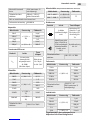
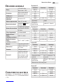
general description
Display
3 ½ digit liquid crystal
display max. value
1999
Polarity Automatic negative
polarity display
Nullication automatic
Measurement
process A/D converter
Overload display only „OL” is displayed
Low battery power The( ) -symbol
appears on the screen
Safety prescriptions
CE EMC/LVD. Device
complies to IEC1010
standard
Protection category II, double insulation
Operating
environment
temperature: 0…40
°C, relative humidity:
< 80%
Storage
environment
temperature: -20…60
°C, relative humidity:
< 80%
Battery 1 x 9V IEC 6F22
Battery
Dimensions 190 mm x 88,5 mm
x27,5 mm
Weight 320g (with Battery)
Accesories
Instructions, connec-
tion cable (red and
black, 1 pair), hitting
pocket protector,
K-type thermometer
probe
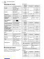
electrical
cHaracteristics
Accuracy +/- (% of displayed value + number of
digits) at 23 +/-5 °C, < 75% relative humidity
DC-voltage
Range Accuracy Resolution
200 mV
+/- (0,5% + 3)
0,1 mV
2 V 1 mV
20 V 10 mV
200 V 100 mV
1000 V +/- (1,0% + 5) 1 V
Impedance 10MΩ
Overload protection 1000 VDC / 700 VAC
AC-voltage
Range Accuracy Resolution
200 mV +/- (1.2% + 3)
2 V
+/- (0.8% + 5)
1 mV
20 V 10 mV
200 V 100 mV
750 V +/- (1.2% + 5) 1 V
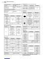
DC-power
Range Accuracy Resolution
2 mA +/- (0,8% + 3) 1 μA
20 mA 10 μA
200 mA +/- (1,2% + 4) 100 μA
20 A +/- (2% + 5) 10 mA
Overload
protection
20 A (maximum 10
seconds long)
Overload
protection
200 mA / 250 V fuse with
"F" mark
At 20A, the measurement limit is not backed
up!
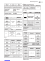
AC-power
Range Accuracy Resolution
2 mA +/- (1,2% + 4) 0,4 μA
20 mA 10 μA
200 mA +/- (2,0% + 4) 100 μA
20 A +/- (3,0% + 5) 10 mA

User Manual EN
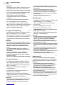
Maximum inward
current 20 A
(for maximum 15
seconds)
20 A (höchstens 15
Sekunde lang)
Overload protection
200 mA / 250 V „F”
type fuse
200 mA / 250 V
Sicherung mit„F”
Zeichen
20 A measuring range not protected!
Frequency range 40-
400 Hz 40-400 Hz
Capacity
Range Accuracy Resolution
20 nF
+/- (2,5% +
20)
10 pF
200 nF 100 pF
2 μF 1 nF
20 μF 10 nF
200 μF +/- (5% + 4) 100 nF
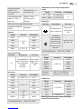
Transistor hFE-Test
Function Description Test state
hFE
The amplication
factor of the transis-
tor is measured
(0-1000)
(All types)
Base current
appr. 10 μA
VCE appr.
2,8 V
Resistance
Range Accuracy Resolution
200 Ω +/- (0,8% + 5) 0,1 Ω
2 kΩ
+/- (0,8% + 3)
1 Ω
20 kΩ 10 Ω
200 kΩ 100 Ω
2 MΩ 1 kΩ
20 MΩ +/- (1,0% +
15) 10 kΩ
200 MΩ +/- (5,0%+
20) 100 kΩ
Overload protection 250V DC/AC RMS
Temperature (with a K type temperature
sensor
Range Accuracy Resolution
-40 °C–400 °C +/- (0,8%+4) 1°C
400 °C–1000 °C +/-(1,5%+15)
Diode-Test
Function Description Test state
The opening vol-
tage is measured
Opening DC
current appr.
1 mA
A beeping
sound indicates
if the resistance
between the V/
Ohm and COM
connectors is less
than 90 Ω
Opening volta-
ge appr. 3 V
Overload protection 250 V DC / AC RMS
Frequency
Range Accuracy Resolution
2 kHz
+/-(0,5%+4)
1 Hz
20 kHz 10 Hz
200 kHz 100 Hz
2 MHz 1 kHz
10 MHz 10 kHz
Overload
protection
250 V DC / AC RMS (for
maximum 15 seconds)
Inductance
Range Accuracy Resolution
2 mH
+/-(2,5%+5)
1 μH
20 mH 10 μH
200 mH 100 μH
2 H 1 mH
20 H +/-(0,5%+4) 10 mH
Warning: Do not connect external voltage
source to the connectors!

EN User Manual
Usage
• Check the 9V battery and press the POWER
button. If the battery is depleted, the battery
symbol appears on the screen.
• The signs near the connectors warn about not
exceeding the inward voltage or current. This is
to prevent damage to the inside circuits.
• Before measuring set the function switch to the
desired position.
• If you are unsure about the magnitude of the
result, set the switch to the highest possible
range and go backwards until you reach the
correct setting.
DC and AC voltage measuring
• Connect the black measuring wire to the „COM”,
and the red one to the „V/ W /Hz” connector.
• Set the function switch to the correct V position
and connect the wires to the voltage source
paralelly.
Note:
• If you are unsure about the magnitude of the result, set the
switch to the highest possible range and go backwards until you
reach the correct setting.
• Set the DC / AC switch to the desired (DC or AC) function.
• If only an „OL” is displayed on the screen, it signals overload.
Switch to a higher range.
• Do not connect voltage exceeding DC 1000 V / AC 700 V to the
connectors. Results may be displayed at higher voltages also, but
this may lead to damage to the inside circuits.
• Do not touch the high voltage circuits while measuring.
DC and AC current measuring
• Connect the black wire to the „COM” and the
red one to the „mA” connector (max. 200 mA)
or the „20A” connector for measuring 200 mA
or 20A.
• Set the function switch to the proper range.
• Connect the the wires to the circuit serially.
• For measuring current between 200 mA and
20A follow the instructions above, but connect
the red wire to the „20A” connector.
Note:
• If you are unsure about the magnitude of the result,
set the switch to the highest possible range and go
backwards until you reach the correct setting.
• If only an „OL” is displayed on the screen, it signals
overload. Switch to a higher range.
• The maximum inward current is 200 mA or 20 A
depending on the connector. (For maximum 15
seconds.)Too much currency overheats the fuse which
needs to be replaced. The 20 A measuring range is not
protected.
• Maximum overload voltage: 200 mV.
Resistance measuring
• Connect the black wire to the „COM”, and the red
one to the „V / W / Ω” connector.
• Set the function switch to the desired resistance
range.
• Touch the wires to the measured circuit paralelly.
Warning: make sure that the measured circuit is
not under power!
• The maximum overload capability for the
connector is 250 V RMS (for maximum 10
seconds).
Note:
• If the measured resistance value is over the maximum
threshold and the device signals overload („OL”), select a
higher range. When measuring above 1 MW it may take a
few seconds for the device to stabilize the displayed value.
This is completely normal for such resistors.
• If you do not connect a resistor to the connector (or there is
a break) the display will show „OL”.
• If you are measuring a resistor that is part of a circuit make
sure that the circuit is not under power and all capacitors are
discharged.
• Do not connect inward voltage to the device as it may lead
to damage to the inside circuits.
• The outward voltage on connectors not under power is
approximately 3 V.
Capacity measuring
• Set the function switch to F position.
• Connect the measured capacitor to the
CX connector. Pay attention to the correct
polarity.
Note:
• If the measured value exceeds the maximum value of the
selected range and the device signals overload („OL”),
select a higher range.
• Unit: 1 nF=10-3 F vagy 1000 pF
• Do not connect external voltage or current to the
connector! Turn o the power and discharge the capacitors
before measuring. Also discharge the electrolyte
capacitors before measuring!
• Before measuring discharge the electrolyte capacitors
more times. (Close the capacitor to 10-20 seconds and V
measure the capacitor if it is discharged.)
Diode and continuity test
• Connect the black measuring wire to the „COM”, the
red one to „V/Ω/Hz” connector. (Note: the polarity of
the red wire is: +)
• Set the function to „ ” position.
• Touch the wires to the diode's connectors. The screen
shows the opening voltage of the diode.
• Connect the wires to two points of the circuit. If the
resistance is below 90 Ω the device beeps.

User Manual EN
Note:
• If you do not connect a unit to the connectors (or there is a
break) the display will show „OL”.
• During the test 1 mA current goes through the diode.
• The display shows the opening voltage of the diode in mV,
and overload if the diode is connected with the polarity
reversed
Temperature measuring
• Set the function switch to °C position.
• Connect the black wire of the temperature
measuring sensor to the „mA” connector and the
red one to the „V/Ω/Hz” connector. Put the sensor
to the place measured. The display shows the
measured value in °C.
Note:
• The device functions with a special temperature measuring
sensor.
• If the sensor is not connected to the connector, the device
displays the temperature of the environment.
• Do not connect outward voltages to the connectors, if the
device is in temperature measuring function.
Transistor hFE test
• Set the function switch to hFE position.
• Determine if the transistor is NPN or PNP and
place it in the proper connector.
• The amplication factor of the transistor is
displayed on the screen.
• IB = 10 μA, VCE = 2,8 V
Frequency measuring
• Connect the measuring wire or the shielded
cable to the „COM” and „V/Ω/Hz” connectors.
• Set the function switch to „Hz” position and
touch the wires to the signal source.
Note:
• Do not measure frequency at a voltage exceeding 250
V(RMS).
• In noisy environment it is advised to use a shielded cable
for measuring small values.
• Avoid touching the circuit when measuring high voltage!
• Frequency measuring changes range automatically.
Inductance measuring
• Set the function swith to the desired
measuring range.
• Connect the measured inductor to the LX
connector.
Bemerkung:
• If the measured inductance is not known, start measuring
at 2 mH range until overload signal turns o.
• Inductors with low inductance function as short circuits. If
possible, do not connect such inductors to the connectors.
Measuring maximum value
• Press PK HOLD button once and the highest value
measured will be displayed.
• Press PK HOLD button once more to turn o the function.
Warning
• When measuring voltage make sure that the wires are
not connected to a current measuring connector and
that the function switch is not in resistance or diode
measuring measuring mode. Always check if you have
connected the wires into the proper connectors.
• Be careful when measuring voltage above 50 V,
especially with high voltage equipment.
• Avoid connecting to „live” circuits.
• Turn off the power in the circuit before connecting the
multimeter to measure current and do not measure
above 20 A.
• Before measuring resistance and diode make sure the
circuit is not under power.
• Always set the function and measuring range
appropriate for the measuring. If in doubt, set the
maximum measuring range and go backwards.
• Make sure that the wire and its isolation is not damaged.
• Only replace fuses to the same type and value.
• When replacing the fuse or battery make sure all
external power sources are turned off and that the
multimeter is turned off as well.

EN User Manual
Handling and
maintenance
Handling
• Keep the multimeter dry. If it is exposed to
moisture wipe it dry immediately. Liquids may
corrode the circuits.
• The multimeter must only be stored and used
at normal temperatures. High temperatures
decrease the lifetime of electronic devices,
damage batteries and distort and damage plastic
parts.
• Handle the multimeter with care. A drop may
damage the circuits and the case which may
cause incorrect operation.
• Protect the multimeter from dust and other dirt
that may cause premature abrasion.
• Clean the multimeter with a wet cloth. Do not
use chemicals, solvents or strong detergents for
cleaning.
Maintenance
• Battery replacement(1 X 9V)
• Disconnect any external circuits from the
device. Turn the multimeter o and remove
the measuring wires from the connectors.
• Unscrew the screw at the bottom and remove
the bottom cover.
• Remove the depleted battery and replace it to
a new one of the same type.
FUse replacement
• Disconnect any external circuits from the
device. Turn the multimeter o and remove
the measuring wires from the connectors.
• Unscrew the screw at the bottom and remove
the bottom cover.
• Replace the melted fuse to one of the same
type and value (5x20 mm, 200 mA / 250 V „F”
type).

Anwendungsinformation DE
allgemeine BescHreiBUng
Display
3 ½ digit Fluid-kristall
max. anzeigbarer Wert
1999
Polarität
Anzeige mit auto-
matisch negative
Polarität
Nullen automatisch
Messprozess A/D Konverter
Überbelastungs-
anzeige
Nur die “OL”-
Überschrift lesbar
Niedrige
Batteriespannung
Das Batterie( )
-Zeichen erscheint auf
der Anzeige
Sicherheitsvor-
schrift
CE EMC/LVD. Der Ap-
parat ist dem IEC1010
Standard entsper-
chend
Berührungs-
schutz Klasse
II. doppeli-
soliert
Betriebs-
temperatur (relative
Luftfeuchte)
0-40 °C (< 80%)
Speicherungs-
temperatur (relative
Luftfeuchte)
-20 °C- +60 °C (< 80%)
Batterie 1 Stück 9V IEC 6F22
Batterie
Größen 190 mm x 88,5 mm
x27,5 mm
Gewicht 320g (mit Batterie)
Zubehöre
Gebrauchsanweisung,
Anschlußleitung (rot
und schwarz, 1 Paar),
Schlagenbeschützer-
Tasche, K-Typ Thermo-
metersonde
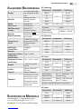
elektroniscHe merkmale
Die Genauigkeit +/- (angezeichneter Wert
in % + die Zahl der Digits) auf 23 +/-5 °C,
beiniedriger als 75% relativer Luftfeuchtigkeit.
DC-Spannung
Messgrenze Genauigkeit Auösung
200 mV
+/- (0,5% + 3)
0,1 mV
2 V 1 mV
20 V 10 mV
200 V 100 mV
1000 V +/- (1,0% + 5) 1 V
Impedanz 10MΩ
Schutz gegen
Überbelastung 1000 VDC / 700 VAC
AC-Spannung
Messgrenze Püntlichkeit Auösung
200 mV +/- (1.2% + 3)
2 V
+/- (0.8% + 5)
1 mV
20 V 10 mV
200 V 100 mV
750 V +/- (1.2% + 5) 1 V
DC-Strom
Messgrenze Genauigkeit Auösung
2 mA +/- (0,8% + 3) 1 μA
20 mA 10 μA
200 mA +/- (1,2% + 4) 100 μA
20 A +/- (2% + 5) 10 mA
Schutz gegen
Überbelastung
20 A (höchstens 10
Sekunde lang)
Schutz gegen
Überbelastung
200 mA / 250 Sicherung
mit V"F" Zeichen
Bei 20A ist die Messgrenze nicht gesichert!
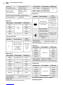
AC-Strom
Messgrenze Püntlichkeit Auösung
2 mA +/- (1,2% + 4) 0,4 μA
20 mA 10 μA
200 mA +/- (2,0% + 4) 100 μA
20 A +/- (3,0% + 5) 10 mA

DE Anwendungsinformation
Maximal
Eingangsleistung
20 A (höchstens 15
Sekunde lang)
Schutz gegen
Überbelastung
200 mA / 250 V
Sicherung mit„F”
Zeichen
Bei 20A ist die Messgrenze nicht gesichert!
Frequenzbereich 40-400 Hz
Kapacität
Messgrenze Genauigkeit Auösung
20 nF
+/- (2,5% +
20)
10 pF
200 nF 100 pF
2 μF 1 nF
20 μF 10 nF
200 μF +/- (5% + 4) 100 nF
Transistor hFE-Test
Funktion Beschreibung Test-
Zustand
hFE
Misst den Strom-
stärkerungsfaktor
des Transistors
(0-1000)
(Jedes Modell)
Basisstrom
ca. 10 μA
VCE kb.
2,8 V
Widerstand
Messgrenze Genauigkeit Auösung
200 Ω +/- (0,8% + 5) 0,1 Ω
2 kΩ
+/- (0,8% + 3)
1 Ω
20 kΩ 10 Ω
200 kΩ 100 Ω
2 MΩ 1 kΩ
20 MΩ +/- (1,0% +
15) 10 kΩ
200 MΩ +/- (5,0%+
20) 100 kΩ
Schutz gegen
Überbelastung 250V DC/AC RMS
Temperatur
(mit K-Typ Sensor für Temperatursmessung)
Messgrenze Genauigkeit Auösung
-40 °C–400 °C +/- (0,8%+4) 1°C
400 °C–1000 °C +/-(1,5%+15)
Diode-Test
Funktion Beschreibung Test
Zustand
Misst die Ein-
gangsspannung
der Diode
DC-Strom in
Eingangsrich-
tung ca. 1 mA
DC-Spannung
in Ausgangs-
richtung ca. 3 V
Wenn der Wider-
stand zwischen
V/Ohm und COM
Steckkontakten
kleiner als 90 Ω
ist,bezeichnet es
Pton
Eingangsspan-
nung ca. 3 V
Schutz gegen
Überbelastung 250 V DC / AC RMS
Frekvenz
Messgrenze Genauigkeit Auösung
2 kHz
+/-(0,5%+4)
1 Hz
20 kHz 10 Hz
200 kHz 100 Hz
2 MHz 1 kHz
10 MHz 10 kHz
Schutz gegen
Überbelastung
250 V DC / AC RMS
(höchstens 15 Sekunde lang)
Induktivität
Messgrenze Genauigkeit Auösung
2 mH
+/-(2,5%+5)
1 μH
20 mH 10 μH
200 mH 100 μH
2 H 1 mH
20 H +/-(0,5%+4) 10 mH
Warnung: Verbinden Sie keine äußere
Spannungsquelle!

Anwendungsinformation DE
Benutzung
• Kontrollieren Sie die 9 V Batterie, dann drücken
Sie die POWER-Taste. Wenn die Batterie leer ist ,
das Zeichen erscheint an der Anzeige.
• Die Hinweiszeichen der Steckdosen warnen
die Eingangsspannung oder Strom den
bezeichneten Wert nicht zu übertreten.
So können Sie die Verletzung der inneren
Stromkreise vermeiden.
• Den Schalter zum Funktionwählen stellen Sie
vor der Messung in die richtige Position (zur
ausgewählten Funktion).
• Wenn Sie die Größenklasse der zu messenden
Menge nicht kennen, stellen Sie den Schalter
auf die größte Messgrenze und davon verlaufen
Sie bis zum entsprechenden Wert zurück.
Messen von DC- und AC-Spannung
• Verbinden Sie den schwarzen Steckkontakt mit
„COM”, den roten Steckkontakt mit „V/ W /Hz” .
• Stellen Sie den Funktionsschalter an die
richtige V-Position und verbinden Sie die
Taster während des Messens parallel mit der
Spannungsquelle .
Bemerkung:
• Wenn Sie die Größenklasse der zu messenden Menge nicht
kennen, stellen Sie den Schalter auf die größte Messungsgrenze
und davon verlaufen Sie bis zum entsprechenden Wert zurück..
• Stellen Sie den DC/AC-Schalter in die richtige (DC oder AC-
Position).
• Wenn nur das Zeichen „OL” an der anzeige sichtbar ist,bedeutet
es Überbelastung.Dabei stellen sie den Funktionsschalter an
größere Messgrenze.
• Schalten sie niemals höcher als DC 1000 V / AC 700 V -Spannung
auf den Eingang. Das Anzeigen ist bei höheren Spannungen
auch möglich,aber es kann Verletzungen der inneren
Stromkreise verursachen.
• Berühren sie die Stromkreise mit Hochspannung bei dem
Messen nicht!
Messen von DC- und AC-Strom
• Verbinden Sie die schwarze Leitung mit
„COM”-Steckkontakt, die rote Leitung mit „mA”
(max. 200 mA) oder „20A” Steckkontakte, zum
200 mA bzw. 20A Messung.
• Stellen Sie den Funktionsschalter zur
entsperchenden Messgrenze.
• Verbinden Sie die Taster sequenziell mit der
Stromquelle zum Messen.
• Zum Strommessen zwischen 200 mA und
20A folgen Sie den nächsten Punkte,aber
verbinden Sie die rote Messleitung mit dem
„20A” -Steckkontakt.
Bemerkung:
• Wenn Sie die Größenklasse der zu messenden Menge
nicht kennen, stellen Sie den Schalter auf die größte
Messungsgrenze und davon verlaufen Sie bis zum
entsprechenden Wert zurück.
• Wenn nur das Zeichen „OL” an der anzeige sichtbar
ist,bedeutet es Überbelastung.Dabei stellen sie den
Funktionsschalter an größere Messgrenze.
• Die maximal Eingangsspannung 200 mA oder 20 A
nach dem gewählten Eingang. (Die Dauer des Tests
ist maximal 15 Sekunde) Die zu große Stromstärke
kann die Sicherung aufschmelzen,dabei muss man es
austauschen.
• Die 20 A Messgrenze ist nicht gesichert.
• Maximal Belastungsspannung: 200 mV.
Widerstandmessen
• Verbinden Sie die schwarze Leitung mit dem
„COM”, und die rote Leitung mit dem„V / W / Ω”
Steckkontakten.
• Stellen Sie den Funktionsschalter an die
gewünschte Messgrenze.
• Drücken Sie die Messspitzen zu dem zu
messenden Stromkreis parallel!
Warnung: Überzeugen Sie,ob der zu messende
Stromkreis spannungslos ist!
• Die maximal Strombelastbarkeit des Einganges:
250 V RMS (höchstens 10 Sekunde lang).
Bemerkung:
• Wenn die Größe des gemessten Widerstandes den
Maximalwert der Messgrenze,und das Gerät zeigt
Überbelastung („OL”), wählen Sie eine höhere
Messgrenze! Widerstände über 1 MW stabilisiert das Gerät
ein paar Sekunde lang den angezeigten Wert.
• Das ist normal bei dem Messen von großen Widerständen.
• Wenn Sie mit dem Eingang keinen Widerstand verbinden
(zBs.wegen Riß),an der Anzeiege erscheint „OL” -Aufschrift
wegen der Messgrenze-Überschritt.
• Wenn Sie Widerstand in Stromkreis kontrolliert,sollen Sie
den spannungslosen Stromkreis bei dem Test sichern,und
die Kondensatoren müssen entladen werden.
• Schalten Sie an das Gerät keine Eingangsspannung,weil
es kann die Verletzung der inneren Stromkreisen
verursachen.
• In ausgelasteten Spangen ist die Ausgangsspannung ca. 3 V.
Kapazitätmessen
• Stellen Sie den Funktionsschalter in F Position.
• Verbinden Sie den Kondensator mit CX
Steckkontakt,beachten Sie auf die richtige
Polarität.
Bemerkung:
• Wenn der Wert des zu messenden Kondensator
überschreitet den Maximalwert der Messgrenze,und das
Gerät zeigt Überbelastung („OL”), wählen Sie eine höhere
Messgrenze.
• Messeinheit: 1 nF=10-3 F vagy 1000 pF
• Verbinden Sie keine äußere Spannung oder Strom mit

DE Anwendungsinformation
dem Steckkontakt. Vor dem Messen schalten Sie die
Speisespannung aus und entladen Sie die Kondensatoren.
• Vor dem Messen entladen Sie die Elektrolyt-
Kondensatoren mehrmals nacheinander.
• (Schließen Sie die Beine des Kondensators für 10-
20 Sekunde zusammen,danach messen Sie sie mit
V-Messung,ob die Entladung erfolgreich war.)
Diode- und Kontinuität-Test
• Verbinden Sie die schwarze Anschlußleitung mit
dem „COM”,- die rote mit dem „V/Ω/Hz” -Steckkontakt.
(Bemerkung: Polarität der roten Taster:+)
• Stellen Sie den Funktionsschalter in „ ” Position.
• Drücken Sie die Taster zu den Ausführungen der Diode.
• An der Anzeige ist die Eingangsspannung der Diode
ist zu sehen.
• Drücken Sie den Taster zu zwei Punkten des
Stromkreises. Sie hören einen Pfiffton,wenn der
Widerstand ist niedriger als 90 Ω.
Bemerkung:
• Wenn Sie mit dem Eingang keienen Bestandteil verbinden
(zBs.:wegen Rißes),an der Anzeige erscheint die „OL”
Überschrift.
• Bei dem Test ießt in der Diode 1 mA Strom.
• An der Anzeige kann die Önungsspannung der Diode in
mV gelesen werden,und es gibt eine Überbelastung ,wenn
Sie die Diode mit umgekehrer Polarität verbunden haben.
Temperaturmessen
• Stellen Sie den Funktionenschalter in °C Position.
• Verbinden Sie die Leitung der Sonde
für Temperaturmessung mit dem„mA”
Steckkontakt, die rote Leitung mit dem „V/Ω/
Hz”Steckkontakt. Legen Sie den Taster da,wo Sie
die Temperatur messen wollen. An der Anzeige
kann die gemessene Temperatur in °C gelesen
werden.
Bemerkung:
• Das Gerät funktioniert mit einer speziellen
Temperaturmessenssonde.
• Wenn Sie die Sonde nicht mit dem Steckkontakt
verbinden,das Gerät zeigt die Außentemperatur.
• Verbinden Sie mit den Eingängen keine
Außenspannung,wenn das Gerät in Temperaturmessen-
Position ist.
Transistor hFE-Test
• Stellen Sie den Funktionsschalter in hFE Position.
• Legen Sie fest,ob der Transistor NPN oder PNP,
und verbinden Sie den Bestandteil mit dem
entsprechenden Steckkontakt.
• An der Anzeige kann den
Stromverstärkungsfaktor des Transistors gelesen
werden.
• IB = 10 μA, VCE = 2,8 V
Frequenzmessen
• Verbinden Sie die Anschlußleitung oder die
geschattene Leitung mit „COM” és a „V/Ω/Hz”
Steckkontakten.
• Stellen Sie den Funktionsschalter in „Hz”
Position,und drücken Sie die Taster zur
Signalsquelle.
Bemerkung:
• Messen Sie niemals Frequenz in höherer Spannung als 250
V(RMS).
• In geräuschvoller Umgebung nutzen Sie geschattene
Leitung zu dem Messen von kleinen Signalen.
• Bei dem Messen von Hochspannung berühren Sie den
Stromkreis nicht.
• Das Gerät in Frequenzmessen-Funktion wechselt die
Messgrenze automatisch.
Induktivitätmessen (L)
• Stellen Sie den Schalter in die gewünschte
Induktivität-Messgrenze.
• Verbinden Sie den zu messenden Wickel mit
dem LX -Steckkontakt.
Bemerkung:
• Wenn die Induktivität des Wickels unbekannt ist,beginnen
Sie das Messen mit Messgrenze 2 mH, und erhöhen Sie es
bis zum Wegfall der Überbelastung.
• Die Wickels mit sehr kleiner Induktivität verhalten sich
als Erdschluß.Wenn es möglich ist,verbinden Sie keinen
solchen Wickel mit dem Steckkontakt.
Erfassung von Spitzenwert
• Drücken Sie die PK HOLD Taste einmal,und das Gerät zeigt
immer den höchsten Wert.
• Zum Ausschaltung der Funktion drücken Sie die PK HOLD
Taste noch einmal.
WarnUng
• Beim Spannungsmessen sichern Sie,daß die Leitungen
sich nicht zu eienem Steckkontakt für Strommessung
und der Funktionsschalter ist nicht in Widerstand-oder
Diodekontroll-Position.Kontrollieren Sie immer,ob
die Leitung mit dem richtigen Steckkontakt der zu
messenden Menge gemäß verbunden haben.
• Seien Sie bitte vorsichtig bei dem Messen von höher als
50 V Spannung,besonders bei Starkstromapparaten!
• Vermeiden Sie den Anschluß zu „lebendigen“
Stromkreisen.
• Bei Strommessen machen Sie den Stromkreis vor dem
Verbinden des Geräts spannungslos.Messen Sie keinen
größeren Strom als 20 A.
• Vor Widerstandmessung und Diode-Test sorgen Sie
für den spannungslosen Stromkreis während des
Messens.
• Wählen Sie immer die richtige Messgrenze und

Anwendungsinformation DE
Funktion. Wenn Sie in der Grössenklasse der zu
messenden Menge nicht sicher sind,wählen Sie
die höchste Messgrenze und davon verlaufen
Sie bis zum entsprechenden Wert zurück.
• Kontrollieren Sie den fehlerlosen Zustand der
Leitung,und die Integrität der Isolierung.
• Tauschen Sie Sicherungen ausgeschlossen auf
Sicherungen mit gleichen Typen und Werten
• Beim Sicherungs-oder Batterieaustausch
schalten Sie alle äußeren Stromkreisen ab,und
schalten Sie das Gerät aus.
BeHandlUng Und
instandHaltUng
Behandlung
• Halten Sie das Gerät immer trocken.Wenn
es Wasser trit,trocknen Sie es sofort ab.Die
Flüßigkeiten korrodieren die Stromkreise
• Nutzen und speichern Sie das Gerät immer an
normaler Temperatur. Die hohe Temperatur
kürzt die Lebensdauer der elektronischen
Geräte,beschädigt die Batterien,und schmelzt
die Bestandteile aus Kunststo.
• Behandeln Sie vorsichtig und sorgfältig das
Gerät. Das Fallenlassen kann die Stromkreise
und das Bedeck beschädigen,was zu dem
fehlerhaften Betrieb des Geräts führt.
• Warnen Sie es vor Staub und anderen
Verschmutzungen,die die zu frühe Abnützung
der Ersatzteile ergeben.
• Es kann mit naßem Tuch gereinigt werden.
• Verwenden Sie keine Chemikalien,Lösungsmittel
oder starke Reinigungsmittel.
Instandhaltung
• Batterieaustausch (1 Stück 9V)
• Schalten Sie jeden Stromkreis vom Gerät ab.
Schalten Sie das Multimeter aus,und entfernen
Sie die Leitung aus dem Steckkontakt.
• Drehen Sie die Schrauben aus,und heben Sie
den unteren Deckel ab.
• Entfernen Sie die leere Batterie,und tauschen
Sie mit einem gleichen Typ.
sicHerUngsaUstaUscH
• Schalten Sie jeden Stromkreis vom Gerät
ab.Stellen Sie den Funktionsschalter in OFF
-Position und ziehen Sie die Leitung aus dem
Steckkontakt aus.
• Drehen Sie die Schrauben aus,und heben Sie
den unteren Deckel ab.
• Tauscen Sie die geschmelzte Sicherung auf
eine mit gleichem Typ und Wert. (5x20 mm,
200 mA / 250 V mit „F” Zeichen)

HU Használati utasítás
általános leírás
Kijelző
3 ½ digites
folyadékkristályos
max. kijelezhető érték
1999
Polaritás automatikus negatív
polaritás kijelzés
Nullázás automatikus
Mérési eljárás A/D konverter
Túlterhelés kijelzés csak az „OL” felirat
látható
Alacsony
telepfeszültség
az elem( )
szimbólum
megjelenik a kijelzőn
Biztonsági előírás
CE EMC/LVD. A
műszer megfelel az
IEC1010 szabványnak
Érintésvédelmi
osztály II. Kettős szigetelésű
Üzemi környezet
hőmérséklet (relatív
páratartalom)
0-40 °C (< 80%)
Tárolási környezet
hőmérséklet (relatív
páratartalom)
-20 °C- +60 °C (< 80%)
Elem 1 db 9V-os IEC 6F22
típusú elem
Méretek 190 mm x 88,5 mm
x27,5 mm
Tömeg 320g (elemmel)
Tartozékok
használati utasítás,
műszerzsinór (piros
és fekete,1 pár),
ütésvédő tok, K
tipusú hőmérő
szonda
elektromos jellemzők
A pontosság +/- (kijelzett érték %-a + digitek
száma) 23 +/-5 °C-on, 75%-nál kisebb relatív
páratartalom esetén
DC feszültség
Méréshatár Pontosság Felbontás
200 mV
+/- (0,5% + 3)
0,1 mV
2 V 1 mV
20 V 10 mV
200 V 100 mV
1000 V +/- (1,0% + 5) 1 V
Impedancia 10MΩ
Túlterhelés elleni
védelem 1000 VDC / 700 VAC
AC feszültség
Méréshatár Pontosság Felbontás
200 mV +/- (1.2% + 3)
2 V
+/- (0.8% + 5)
1 mV
20 V 10 mV
200 V 100 mV
750 V +/- (1.2% + 5) 1 V
DC áram
Méréshatár Pontosság Felbontás
2 mA +/- (0,8% + 3) 1 μA
20 mA 10 μA
200 mA +/- (1,2% + 4) 100 μA
20 A +/- (2% + 5) 10 mA
Maximális bemenő
áram
20 A (maximum 10
másodpercig)
Túlterhelés elleni
védelem
200 mA / 250 V"F"
jelzésű biztosíték
20 A-es méréshatár nincs biztosítva!
AC áram
Méréshatár Pontosság Felbontás
2 mA +/- (1,2% + 4) 0,4 μA
20 mA 10 μA
200 mA +/- (2,0% + 4) 100 μA
20 A +/- (3,0% + 5) 10 mA

Használati utasítás HU
Maximális bemenő
áram
20 A (maximum 15
másodpercig)
Túlterhelés elleni
védelem
200 mA / 250 V „F”
jelzésű biztosíték
20 A-es méréshatár nincs biztosítva!
Frekvencia tartomány 40-400 Hz
Kapacitás
Méréshatár Pontosság Felbontás
20 nF
+/- (2,5% +
20)
10 pF
200 nF 100 pF
2 μF 1 nF
20 μF 10 nF
200 μF +/- (5% + 4) 100 nF
Tranzisztor hFE teszt
Funkció Leírás Teszt
állapot
hFE
A tranzisztor
áramerősítési
tényezőjét méri
(0-1000)
(Minden típus)
Bázisáram
kb. 10 μA
VCE kb. 2,8 V
Ellenállás
Méréshatár Pontosság Felbontás
200 Ω +/- (0,8% + 5) 0,1 Ω
2 kΩ
+/- (0,8% + 3)
1 Ω
20 kΩ 10 Ω
200 kΩ 100 Ω
2 MΩ 1 kΩ
20 MΩ +/- (1,0% +
15) 10 kΩ
200 MΩ +/- (5,0%+
20) 100 kΩ
Túlterhelés elleni
védelem 250V DC/AC RMS
Hőmérséklet (K típusú hőmérsékletmérő szenzorral)
Méréshatár Pontosság Felbontás
-40 °C–400 °C +/- (0,8%+4) 1°C
400 °C–1000 °C +/-(1,5%+15)
Dióda teszt
Funkció Leírás Teszt állapot
A dióda
nyitófeszültségét
méri
Nyitóirányú DC
áram kb. 1 mA
Záró irányú DC
feszültség kb.
3 V
Sípoló hang jelzi,
ha a V/Ohm és a
COM csatlakozók
közötti ellenállás
kisebb, mint
90 Ω
Nyitófeszültség
kb. 3 V
Túlterhelés elleni
védelem 250 V DC / AC RMS
Frekvencia
Méréshatár Pontosság Felbontás
2 kHz
+/-(0,5%+4)
1 Hz
20 kHz 10 Hz
200 kHz 100 Hz
2 MHz 1 kHz
10 MHz 10 kHz
Túlterhelés elleni
védelem
250 V DC / AC
RMS (maximum 15
másodpercig)
Induktivitás
Méréshatár Pontosság Felbontás
2 mH
+/-(2,5%+5)
1 μH
20 mH 10 μH
200 mH 100 μH
2 H 1 mH
20 H +/-(0,5%+4) 10 mH
Figyelmeztetés: Ne csatlakoztasson a
kapcsokra külső feszültségforrást!

HU Használati utasítás
Használat
• Ellenőrizze a 9 V-os elemet, majd nyomja be
a POWER gombot. Ha az elem lemerült, az
akkumulátor szimbólum megjelenik a kijelzőn.
• Az aljzatok melletti jelzések gyelmeztetnek,
hogy a bemenő feszültség vagy áram
ne haladja meg a jelzett értéket. Így
megakadályozhatja a belső áramkörök
sérülését.
• A funkcióválasztó kapcsolót a mérés előtt
állítsa a megfelelő állásba (funkcióhoz)
• Ha a mérendő mennyiség nagyságrendjét
nem ismeri, állítsa a kapcsolót a legmagasabb
méréshatárra és onnan haladjon visszafelé,
amíg a megfelelő értéket eléri.
DC és AC feszültség mérése
• Csatlakoztassa a fekete csatlakozót a „COM”, a
piros csatlakozót a „V/ W /Hz” aljzatba.
• Állítsa a funkcióválasztó kapcsolót a megfelelő
V pozícióba és csatlakoztassa a tapogatókat
párhuzamosan a feszültségforrással a mérés
idejére.
Megjegyzés:
• Ha a mérendő mennyiség nagyságrendjét nem ismeri,
állítsa a kapcsolót a legmagasabb méréshatárra és onnan
haladjon visszafelé, amíg a megfelelő értéket eléri.
• Állítsa a DC / AC kapcsolót a megfelelő (DC vagy AC)
módba.
• Ha csak az „OL” látható a kijelzőn, az a túlterhelést
jelzi. Ilyenkor kapcsolja a funkciókapcsolót magasabb
méréshatárba.
• Ne kapcsoljon DC 1000 V / AC 700 V-nál magasabb
feszültséget a bemenetre. A kijelzés lehetséges
magasabb feszültségeken is, de ez a belső áramkörök
sérüléséhez vezethet.
• Ne érintse a nagyfeszültségű áramköröket mérés közben.
DC és AC áram mérése
• Csatlakoztassa a fekete vezetéket a „COM”, a
piros vezetéket pedig a „mA” (max. 200 mA)
vagy „20A” jelzésű aljzatba, 200 mA-es illetve
20A-es méréshez.
• Állítsa a funkció kapcsolót a megfelelő
méréshatárhoz.
• Csatlakoztassa a tapogatókat sorosan az
áramforrással a méréshez.
• 200 mA és 20A közötti áram méréséhez az
előző pontokat kövesse, de a piros mérőzsinórt
a „20A” jelzésű aljzatba csatlakoztassa.
Megjegyzés:
• Ha a mérendő áram nagyságrendjét nem ismeri, állítsa
a kapcsolót a legmagasabb méréshatárra és onnan
haladjon visszafelé, amíg a megfelelő értéket eléri.
• Ha csak az „OL” látható a kijelzőn, az a túlterhelést
jelzi. Ilyenkor kapcsolja a funkciókapcsolót magasabb
méréshatárba.
• A maximális bemenő áram 200 mA vagy 20 A a
választott bemenettől függően. (A teszt ideje max. 15
másodperc.) A túl nagy áramerősség a biztosítékot
kiolvasztja, amit ki kell cserélni. A 20 A-es méréshatár
nincs biztosítva.
• Maximális terhelőfeszültség: 200 mV.
Ellenállásmérés
• Csatlakoztassa a fekete vezetéket a „COM”, a piros
vezetéket pedig a „V / W / Ω” aljzatba.
• Állítsa a funkciókapcsolót a kívánt ellenállás
méréshatárra.
• Érintse a mérőhegyeket a mérendő
áramkörhöz, de azzal párhuzamosan.
Figyelmeztetés: biztosítsa a mérendő áramkör
feszültségmentességét!
• A bemenet maximális túlterhelhetősége: 250 V
RMS (max. 10 másodpercig).
Megjegyzés:
• Ha a mérendő ellenállás értéke meghaladja a méréshatár
maximális értékét, és a műszer túlterhelést jelez („OL”),
válasszon egy magasabb méréshatárt. 1 MW fölötti
ellenállásoknál a műszer néhány másodperc alatt
stabilizálja a kijelzett értéket. Ez teljesen normális nagy
értékű ellenállások mérésénél.
• Ha a bemenetre nem csatlakoztat ellenállást (pl. szakadás),
a kijelzőn az „OL” felirat jelenik meg a méréshatár túllépés
miatt.
• Ha áramkörben lévő ellenállást vizsgál, biztosítsa, hogy
a teszt alatt az áramkör feszültségmentes legyen, és a
kondenzátorok legyenek kisütve.
• Ne kapcsoljon a műszerre bemenő feszültséget, mert az a
belső áramkörök sérüléséhez vezethet.
• Terheletlen kapcsokon a kimeneti feszültség kb. 3 V.
Kapacitásmérés
Állítsa a funkcióválasztó kapcsolót a F állásba.
Csatlakoztassa a kondenzátort a CX jelű aljzatba,
ügyelve a helyes polaritásra, amikor szükséges.
Megjegyzés:
• Ha a mérendő kondenzátor értéke meghaladja a
méréshatár maximális értékét, és a műszer túlterhelést
jelez („OL”), válasszon egy magasabb méréshatárt.
• Mértékegység: 1 nF=10-3 F vagy 1000 pF
• Ne csatlakoztasson külső feszültséget vagy áramot az
aljzatba. Mérés előtt kapcsolja ki a tápfeszültséget és a
kondenzátorokat süsse ki.
• Mérés előtt az elektrolit kondenzátorokat többször süsse
ki egymás után. (Zárja össze a kondenzátor lábait 10-20
mp-re, majd mérjen rá V méréssel a kondenzátor lábaira,
hogy sikerült-e kisütni az alkatrészt)

Használati utasítás HU
Dióda és folytonosság teszt
• Csatlakoztassa a fekete műszerzsinórt a „COM”, a
pirosat a „V/Ω/Hz” aljzatba. (Megjegyzés: a piros
tapogató polaritása: +)
• Állítsa a funkció kapcsolót a állásba.
• Érintse a tapogatókat a dióda kivezetéseihez. A
kijelzőn a dióda nyitófeszültsége látható.
• Érintse a tapogatókat az áramkör két pontjára.
Sípoló hang jelez, ha az ellenállás kisebb 90 Ω-nál.
Megjegyzés:
• Ha a bemenetre nem csatlakoztat alkatrészt (pl. szakadás),
a kijelzőn az „OL” felirat jelenik meg.
• A diódán 1 mA áram folyik a teszt alatt.
• A kijelzőn a dióda nyitófeszültsége olvasható mV-
ban, és túlterhelés, ha a diódát fordított polaritással
csatlakoztatta.
Hőmérséklet mérés
• Állítsa a funkciókapcsolót a °C állásba
• Helyezze a hőmérsékletmérő szonda fekete
csatlakozóját a „mA” jelű aljzatba, a piros
csatlakozót pedig a „V/Ω/Hz”aljzatba. Az
érzékelőt helyezze a mérendő hőmérsékletű
helyre. A kijelzőn a mért hőmérséklet
olvasható °C-ban.
Megjegyzés:
• A műszer speciális hőmérséklet-mérő szondával működik.
• Ha a szondát nem csatlakoztatjuk az aljzatba, akkor a
műszer a környezete hőmérsékletét mutatja.
• Ne kapcsoljon a bemenetekre külső feszültséget, ha a
műszer hőmérséklet-mérő állásban van.
Tranzisztor hFE teszt
• Állítsa a funkciókapcsolót a hFE állásba
• Határozza meg, hogy a tranzisztor NPN vagy
PNP, és helyezze az alkatrészt a lábkiosztásának
megfelelő csatlakozóba.
• A kijelzőről a tranzisztor áramerősítési
tényezője olvasható le.
IB = 10 μA, VCE = 2,8 V
Frekvenciamérés
• Csatlakoztassa a műszerzsinórt vagy az
árnyékolt kábelt a „COM” és a „V/Ω/Hz”
aljzatokba.
• Állítsa a funkciókapcsolót „Hz” állásba és
érintse a tapogatókat a jelforráshoz.
Megjegyzés:
• Ne mérjen 250 V(RMS)nál nagyobb feszültségen
frekvenciát.
• Zajos környezetben célszerű árnyékolt kábelt használni kis
jelek mérésénél.
• Nagyfeszültségű mérésnél kerülje az áramkör érintését.
• A frekvenciamérés automata méréshatár-váltós.
Induktivitás (L) mérés
Állítsa a funkciókapcsolót a kívánt induktivitás
méréshatárba
Csatlakoztassa a mérendő tekercset az LX aljzatba.
Megjegyzés:
• Ha a tekercs induktivitása nem ismert, kezdje a mérést a
2 mH méréshatárnál, és addig növelje, amíg a túlterhelés
jelzés meg nem szűnik.
• A nagyon kis induktivitású tekercsek rövidzárként
viselkednek. Ha lehetséges, ne helyezzen ilyen tekercseket
az aljzatba.
Csúcsérték rögzítés
• Nyomja meg a PK HOLD gombot egyszer és a műszer a
kijelzőn mindig a legmagasabb mért értéket mutatja.
• Nyomja meg a PK HOLD gombot még egyszer a funkció
kikapcsolásához.
Figyelmeztetés
• Feszültség mérésénél biztosítsa, hogy a
vezetékek ne csatlakozzanak árammérő aljzathoz
és a funkciókapcsoló ne legyen ellenállás vagy
dióda ellenőrző állásban. Mindig ellenőrizze,
hogy a mérendő mennyiségnek megfelelő
aljzatba csatlakoztatta-e a vezetéket.
• Legyen körültekintő 50 V-nál nagyobb
feszültség mérésekor, különösen erősáramú
berendezéseknél.
• Kerülje az „élő” áramkörökhöz való csatlakozást.
• Árammérésnél az áramkört feszültségmentesítse,
mielőtt csatlakoztatná hozzá a multimétert. Ne
mérjen 20 A-nél nagyobb áramot.
• Ellenállásmérés és dióda tesztelés
előtt gondoskodjon az áramkör
feszültségmentesítéséről a mérés idejére.
• Mindig a mérésnek megfelelő funkciót és
méréshatárt válassza. Ha kétséges a mérendő
mennyiség nagyságrendje, válassza a
legmagasabb méréshatárt és onnan haladjon
visszafelé.
• Győződjön meg a műszerzsinór hibátlan
állapotáról, a szigetelés sértetlenségéről.
• Biztosítékot csak azonos típusúra és értékűre
cseréljen.
• Biztosíték- vagy elemcserénél a műszer tokjának
kinyitása előtt kapcsoljon le minden külső
áramkört és kapcsolja ki a multimétert.

HU Használati utasítás
kezelés és karBantartás
Kezelés
• Tartsa a multimétert szárazon. Ha nedvesség
éri, törölje le azonnal. A folyadékok korrodálják
az áramköröket.
• A multimétert tárolni és használni csak normál
hőmérsékleten szabad. A magas hőmérséklet
rövidíti az elektronikus eszközök élettartamát,
megrongálja az elemeket, és eltorzítja,
megolvasztja a műanyag alkatrészeket.
• Bánjon óvatosan és gondosan a multiméterrel.
Az elejtés kárt tesz az áramkörökben és a
tokban, ami a multiméter helytelen működését
okozza.
• Óvja a multimétert a portól és egyéb
szennyeződésektől, amik az alkatrészek idő
előtti kopását eredményezik.
• A multimétert nedves ruhával tisztíthatja. Ne
alkalmazzon vegyszereket, oldószereket vagy
erős tisztítószereket a tisztításhoz.
Karbantartás
• Elemcsere (1 db 9V-os)
• Kapcsoljon le minden külső áramkört a
műszerről. Kapcsolja ki a multimétert és a
műszerzsinórt húzza ki az aljzatból.
• Csavarja ki a csavarokat és emelje le az alsó
fedelet.
• Távolítsa el a lemerült elemet és cserélje ki
ugyanolyan típusúra.
Biztosítékcsere
• Kapcsoljon le minden külső áramkört a
műszerről. Állítsa a funkciókapcsolót OFF
állásba és a műszerzsinórt húzza ki az aljzatból.
• Csavarja ki a csavarokat és emelje le az alsó
fedelet.
• Cserélje ki a kiolvadt biztosítékot ugyanolyan
típusúra és értékűre. (5x20 mm, 200 mA / 250
V „F” jelzésű.)

Manual de utilizare RO
descriere generală
Aşaj LCD cu 3½ cifre
aşare max. 1999
Polaritate aşare automată de
polaritate negativă
Calibrare 0 automatică
Metoda de
măsurare convertor A/D
Aşare suprasarcină doar „OL” se vede
Baterie descărcată simbolul( )apare
pe aşaj
Norme de securitate
CE EMC/LVD. Aparatul
corespunde normelor
IEC1010
Clasa de protecţie II. Izolaţie dublă
Mediu de lucru
Temp
(Umiditate relativă)
0-40 °C (< 80%)
Mediu de stocare
Temp
(Umiditate relativă)
-20 °C- +60 °C (< 80%)
Baterie 1 buc 9V tip IEC 6F22
Dimensiuni 190 mm x 88,5 mm
x27,5 mm
Greutate 320g (cu baterie)
Accesorii
manual de utilizare,
cabluri de măsurat
(roşu şi negru, 1 per),
husă antişoc, sondă
termometrică tip K
caracteristici electrice
Acurateţea +/- (% valorii aşate + nr. cifrelor) a
fost stabilită la 23 +/-5 °C, la umiditate relativă
< 75%
Tensiune DC
Domeniu Acurateţe Rezoluţie
200 mV
+/- (0,5% + 3)
0,1 mV
2 V 1 mV
20 V 10 mV
200 V 100 mV
1000 V +/- (1,0% + 5) 1 V
Impedanţa 10MΩ
Protecţie la
suprasarcină 1000 VDC / 700 VAC
Tensiune AC
Domeniu Acurateţe Rezoluţie
200 mV +/- (1.2% + 3)
2 V
+/- (0.8% + 5)
1 mV
20 V 10 mV
200 V 100 mV
750 V +/- (1.2% + 5) 1 V
Curent DC
Domeniu Acurateţe Rezoluţie
2 mA +/- (0,8% + 3) 1 μA
20 mA 10 μA
200 mA +/- (1,2% + 4) 100 μA
20 A +/- (2% + 5) 10 mA
Curent de intrare
maximă
20 A (maximum 10
secunde)
Protecţie la
suprasarcină
200 mA / 250 V fuzibil
tip "F"
Domeniul de 20 A neasigurat!
Curent AC
Domeniu Acurateţe Rezoluţie
2 mA +/- (1,2% + 4) 0,4 μA
20 mA 10 μA
200 mA +/- (2,0% + 4) 100 μA
20 A +/- (3,0% + 5) 10 mA

RO Manual de utilizare
Curent de intrare
maximă
20 A (maximum 10
secunde)
Protecţie la
suprasarcină
200 mA / 250 V fuzibil
tip "F"
Domeniul de 20 A neasigurat!
Domeniu de
frecvenţă 40-400 Hz
Capacitate
Domeniu Acurateţe Rezoluţie
20 nF
+/- (2,5% +
20)
10 pF
200 nF 100 pF
2 μF 1 nF
20 μF 10 nF
200 μF +/- (5% + 4) 100 nF
Test tranzistor hFE
Funcţia Descriere Stare test
hFE
Măsoară
coecientul
de amplicare
în curent al
tranzistorului
(0-1000)
(Toate tipurile)
Curent
bazic cca.
10 μA
VCE cca.
2,8 V
Rezistenţă
Domeniu Acurateţe Rezoluţie
200 Ω +/- (0,8% + 5) 0,1 Ω
2 kΩ
+/- (0,8% + 3)
1 Ω
20 kΩ 10 Ω
200 kΩ 100 Ω
2 MΩ 1 kΩ
20 MΩ +/- (1,0% +
15) 10 kΩ
200 MΩ +/- (5,0%+
20) 100 kΩ
Protecţie la
suprasarcină 250V DC/AC RMS
Temperatură (cu sensor termometric tip K)
Domeniu Acurateţe Rezoluţie
-40 °C–400 °C +/- (0,8%+4) 1°C
400 °C–1000 °C +/-(1,5%+15)
Diode test
Funcţia Descriere Stare test
Măsoară
tensiunea de
deschidere al
diodei
Curent DC
direct cca. 1 mA
Tensiune DC
invers cca. 3 V
Piuit
semnalizează
dacă între V/
Ohm şi COM
rezistenţa este
mai mică de
90 Ω
Tensiunea de
deschidere cca.
3 V
Protecţie la
suprasarcină 250 V DC / AC RMS
Frecvenţă
Domeniu Acurateţe Rezoluţie
2 kHz
+/-(0,5%+4)
1 Hz
20 kHz 10 Hz
200 kHz 100 Hz
2 MHz 1 kHz
10 MHz 10 kHz
Protecţie la
suprasarcină
250 V DC / AC RMS
(max. 15 secunde)
Inductivitate
Domeniu Acurateţe Rezoluţie
2 mH
+/-(2,5%+5)
1 μH
20 mH 10 μH
200 mH 100 μH
2 H 1 mH
20 H +/-(0,5%+4) 10 mH
Atenţie: Nu conectaţi la borne sursă de
tensiune exterioară!

Manual de utilizare RO
Utilizare
• Vericaţi bateria de 9 V, comutaţi butonul
POWER la poziţia ON. Dacă bateria s-a
descărcat simbolul apare pe aşaj.
• Semnele lângă bananele de conectare vă
avertizează să nu depăşească tensiunea sau
curentul de intrare nivelurile aşate. Astfel
puteţi evita deteriorarea circuitelor din interior.
• Înainte de măsurare comutatorul de funcţii
comutaţi la poziţia corectă (la funcţia dorită).
• Dacă nu cunoaşteţi domeniul nivelului valorii
ce doriţi a măsura, selectaţi domeniul cel mai
mare cu comutatorul de funcţii şi de acolo
să reveniţi la domeniu de măsurare mai mică
până atingeţi nivelul dorit.
Măsurare tensiune DC şi AC
• Conectaţi cablul de măsurare negru la „COM”,
iar cel roşu la „V/Ω/Hz”.
• Comutaţi selectorul de funcţii la poziţia V
potrivit şi conectaţi tentaculele în paralel cu
sursa de tensiune pe timpul măsurării.
Notă:
• Dacă nu cunoaşteţi domeniul nivelului valorii ce doriţi a
măsura, selectaţi domeniul cel mai mare cu comutatorul
de funcţii şi de acolo să reveniţi la domeniu de măsurare
mai mică până atingeţi nivelul dorit.
• Comutaţi comutatorul DC/AC la modul (DC sau AC) dorit.
• Dacă pe aşaj apare doar „OL”, aparatul vă indică
suprasarcină. În acest caz comutaţi la domeniu de
măsurat mai mare.
• Nu conectaţi la intrare tensiune mai mare de DC 1000 V/
AC 700 V. Aşarea este posibilă şi la tensiuni mai mari dar
riscaţi integritatea circuitelor interioare.
• Nu atingeţi circuitele de înaltă tensiune în timpul
măsurării.
Măsurare curent DC şi AC
• Conectaţi cablul de măsurare negru la „COM”,
iar cel roşu la „mA” (max. 200 mA) sau la „20A”,
pentru măsurare până la 200 mA respectiv 20A.
• Aşezaţi comutatorul de funcţii la domeniul de
măsurat corespunzător.
• Conectaţi tentaculele în serie cu sursa de
curent pentru măsurare.
• Pentru măsurarea curentului între 200 mA şi
20 A urmaţi punctele de mai sus, dar cablul de
măsurat roşu conectaţi la „20A”.
Notă:
• Dacă nu cunoaşteţi domeniul nivelului valorii ce doriţi a
măsura, selectaţi domeniul cel mai mare cu comutatorul
de funcţii şi de acolo să reveniţi la domeniu de măsurare
mai mică până atingeţi nivelul dorit.
• Dacă pe aşaj apare doar „OL”, aparatul vă indică
suprasarcină. În acest caz comutaţi la domeniu de
măsurat mai mare.
• Curentul maxim de intrare este 200 mA sau 20 A în
funcţie de banana de intrare aleasă. (Timpul testului
este max. 15 secunde.) Curentul prea mare topeşte
fuzibilul care pe urmă trebuie schimbat. Domeniul 20 A
nu are fuzibil.
• Tensiunea de sarcină maximă: 200 mV.
Măsurare rezistor
• Conectaţi cablul de măsurare negru la „COM”, „V/
Ω /Hz”.
• Aşezaţi comutatorul de funcţii la domeniul de
rezistenţă dorită.
• Atingeţi vârfurile tentaculelor la circuitul de
măsurat dar în paralel cu el.
Atenţie: asiguraţi-vă ca circuitul de măsurat să
e scos de sub tensiune.
• Sarcina maximă de intrare: 250 V RMS (max. 10
secunde).
Notă:
• Dacă valoarea rezistenţei măsurate depăşeşte nivelul
maxim al domeniului de măsurat ales, şi aparatul indică
suprasarcină („OL”), alegeţi un domeniu de măsurat mai
mare. La rezistoare peste 1 M aparatul are nevoie de
câteva secunde până la stabilirea valorii măsurate. Acest
lucru este absolut normal la măsurarea rezistoarelor de
valoare mare.
• Dacă nu conectaţi rezistor la tentaculele aparatului
(ex. ruptură), pe aşaj apare „OL” indicând depăşirea
domeniului de măsurat.
• Dacă testaţi rezistor în circuit, asiguraţi-vă să e circuitul
scos de sub tensiune pe timpul testului şi condensatoarele
să e descărcate.
• Nu conectaţi la aparat tensiune de intrare, întrucât puteţi
deteriora circuitele aparatului.
• Pe bornele fără sarcină tensiunea de ieşire este cca. 3 V.
Măsurare capacitate
• Aşezaţi comutatorul de funcţii în poziţia F.
• Conectaţi condensatorul în borna CX, având
grijă la polaritatea corectă dacă este cazul.
Notă:
• Dacă valoarea condensatorului ce va măsurat depăşeşte
nivelul maxim al domeniului de măsurat ales şi aparatul
indică suprasarcină („OL”), alegeţi un domeniu de măsurat
mai mare.
• Unitate de măsură: 1 nF=10-3 F sau 1000 pF
• Nu conectaţi tensiune sau curent exterior în bornă.
Înainte de măsurare opriţi sursa şi condensatoarele să le
descărcaţi.
• Înainte de măsurare condensatoarele electrolitice să le
descărcaţi de mai multe ori. (Scurtcircuitaţi picioarele
condensatorului timp de 10-20 sec., pe urmă măsuraţi
tensiune la picioarele condensatorului, asigurându-vă că
aţi reuşit să descărcaţi condensatorul)

RO Manual de utilizare
Test diode şi continuitate
• Conectaţi cablul de măsurare negru la „COM”,
iar cel roşu la „V/Ω/Hz”. (Notă: tentaculul roşu
are polaritatea: +)
• Aşezaţi comutatorul de funcţii la poziţia .
• Atingeţi tentaculele la terminalele diodei. Pe aşaj
se citeşte tensiunea de deschidere al diodei.
• Atingeţi tentaculele la 2 puncte dorite în
circuit. Piuit semnalizează dacă rezistenţa este
mai mică de 90 Ω.
Notă:
• Dacă la intrare nu conectaţi component (ex. ruptură), pe
aşaj apare „OL”.
• În timpul testului dioda este parcursă de 1 mA curent.
• Pe aşaj se citeşte tensiunea de deschidere al diodei în mV,
şi suprasarcină dacă dioda conectăm în sens invers.
Măsurare temperatură
• Aşezaţi comutatorul de funcţii la °C
• Potriviţi contactul negru al sondei de
temperatură la „mA”, iar cel roşu la „V/Ω/Hz”.
Senzorul aşezaţi la locul unde doriţi măsura
temperatură. Pe aşaj se citeşte temperatura
măsurată în °C.
Notă:
• Aparatul funcţionează cu sondă de temperatură specială.
• Dacă sonda nu conectaţi la aparat, se va aşa temperatura
ambiantă.
• Nu conectaţi la intrări tensiune exterioară dacă aparatul
este setat la domeniul de temperatură.
Test tranzistor hFE
• Aşezaţi comutatorul de funcţii la poziţia hFE
• Determinaţi că tranzistorul este NPN sau
PNP şi aşezaţi în soclul corespunzător ordinii
picioarelor lui.
• Pe aşaj se citeşte coecientul de amplicare
al tranzistorului.
• IB = 10 μA, VCE = 2,8 V
Măsurare frecvenţă
• Conectaţi cablul de măsurat sau cablul ecranat
la „COM” şi la „V/Ω/Hz”.
• Aşezaţi comutatorul de funcţii la „Hz” şi
atingeţi tentaculele la sursa de semnal.
Notă:
• Nu măsuraţi frecvenţă la tensiune mai mare de 250
V(RMS).
• Într-un mediu zgomotos este indicat utilizarea cablului
de test ecranat la măsurarea semnalelor slabe.
• La măsurare sub înaltă tensiune evitaţi atingerea
circuitului.
• Măsurarea de frecvenţă este cu domeniu de măsurat
automat.
Măsurare inductivitate (L)
• Aşezaţi comutatorul de funcţii la domeniul de
măsurare inductivitate dorit
• Conectaţi bobina ce va măsurată la borna LX.
Notă:
• Dacă inductivitatea bobinei nu cunoaşteţi, începeţi
măsurarea în domeniul 2 mH şi măriţi până indicatorul
suprasarcină nu dispare.
• Bobinele cu inductivitate foarte mică se comportă ca şi
scurtcircuit. Dacă se poate nu conectaţi astfel de bobine
la aparat.
Aşare valori de vârf
• Apăsaţi butonul PK HOLD odată şi pe aşajul aparatului va
aşat tot timpul valoarea de vârf măsurată.
• Apăsaţi butonul PK HOLD încă odată pentru a opri această
funcţie.
atenţie
• La măsurare tensiune asiguraţi-vă să nu e
conectate cablurile de măsurat la borne de
măsurat curent şi comutatorul de funcţii să
nu e în poziţia rezistenţă sau test diode.
Vericaţi întotdeauna să e cablurile de măsurat
conectate la bornele corespunzătoare nivelului
de măsurare dorită.
• Fiţi prudent la măsurare peste tensiunea de 50 V,
în mod deosebit la aparate de curenţi tari.
• Evitaţi conexiunea la circuite „vii”.
• La măsurare curent scoateţi circuitul de sub
tensiune înainte să conectaţi multimetrul. Nu
măsuraţi curent peste 20 A.
• Înainte de măsurare rezistenţă sau diode scoateţi
circuitul de sub tensiune pe timpul măsurării.
• Alegeţi totdeauna funcţia şi domeniul potrivit
măsurării de efectuat. Dacă domeniul de măsurat
al valorii ce va măsurat nu este sigur, alegeţi
domeniul cel mai mare şi coborâţi de acolo
începând.
• Asiguraţi-vă de starea cablurilor de măsurat să e
fără defecţiuni şi izolaţia să e impecabilă.
• Fuzibilul să schimbaţi doar cu tipul şi valoarea
identică.
• La schimbarea fuzibilului sau a bateriei înainte
de deschiderea carcasei aparatului îndepărtaţi
aparatul din orice fel de circuit şi opriţi aparatul.
Pagina se încarcă...
Pagina se încarcă...
Pagina se încarcă...
Pagina se încarcă...
Pagina se încarcă...
Pagina se încarcă...
Pagina se încarcă...
Pagina se încarcă...
-
 1
1
-
 2
2
-
 3
3
-
 4
4
-
 5
5
-
 6
6
-
 7
7
-
 8
8
-
 9
9
-
 10
10
-
 11
11
-
 12
12
-
 13
13
-
 14
14
-
 15
15
-
 16
16
-
 17
17
-
 18
18
-
 19
19
-
 20
20
-
 21
21
-
 22
22
-
 23
23
-
 24
24
-
 25
25
-
 26
26
-
 27
27
-
 28
28


în alte limbi
- slovenčina: Maxwell 25304 Používateľská príručka
- Deutsch: Maxwell 25304 Benutzerhandbuch
Lucrări înrudite
Alte documente
-
Somogyi SMA 92 Manual de utilizare
-
Defort 93728564 User`s manual
-
Hama 00223565 Manual de utilizare
-
-
Emos M0430 Instrucțiuni de utilizare
-
Stanley FMHT0-77421 Manual de utilizare
-
Facom 711A Manualul proprietarului
-
-
-