
2202019000_31-M0430_00_01 74 × 105 mm
M0430
GB Digital Multimeter
CZ Digitální multimetr
SK Digitálny multimeter
PL Multimetr cyfrowy
HU Digitális multiméter
SI Digitalni multimeter
RS|HR|BA|ME Digitalni multimetar
DE Digitales Multimeter
UA Цифровий мультиметр
RO|MD Multimetru digital
LT Skaitmeninis multimetras
LV Digitālais multimetrs
EE Digitaalne multimeeter
BG Цифров мултиметър
www.emos.eu

2
1
2
3
9
4
85
10
76
1

3
2
GB | Digital Multimeter
Read this instruction manual thoroughly before you begin using
the M0430. It contains particularly important passages concerning
occupational safety principles when using the device. Such passages
are highlighted. Reading the manual will prevent potential injury by
electric current or damage to the device.
The multimeter was designed in accordance with standard EN
61010-1, applying to electronic measuring instruments belonging
to category CAT III 600 V/CAT II 1000 V, pollution degree 2. CAT III is
intended for measuring circuits powered by xed wiring installations,
such as relays, sockets, distribution boxes, feeder lines and short
branching circuits and lighting systems in large buildings.
Category CAT II is intended for measurements made on circuits
directly connected to low-voltage installations (e.g. household
appliances, portable tools and similar equipment).
Do not use the multimeter to measure ranges that fall into the
category IV!
Warning:
Use the M0430 multimeter only in the manner specied below. Other
uses may cause damage to the device or endanger your health.
Comply with the following instructions:
• Before measuring resistance, diodes or current, disconnect the
circuits from the power supply and discharge any high-voltage
A
B

4
capacitors. Use a function appropriate for the given measure-
ment. Before changing the range (or switching functions) dis-
connect the conductors from the circuit that is being measured.
• Make sure the device is undamaged before you begin using the
multimeter. If you nd obvious signs of damage on the body of
the device, do not make any measurements! Check that the
surface of the multimeter does not have scratches and that the
side joints are not coming apart.
• Also check the insulation on the measuring probes. Damaged
insulation may result in injury by electric current. Do not use
damaged measuring probes!
• Do not measure voltages above 1000 V! If you intend to measure
current, check the multimeter‘s fuse and turn o the power
supply to the circuit before you connect the multimeter. Before
measuring, make sure the circular switch for setting measuring
range is in the correct position. Under no circumstances should
you make any changes to the measuring range (by moving the
circular switch for changing measuring programmes) while
measuring! Doing so could damage the device. When you are
measuring, rst connect the black conductor (probe) and then
the red conductor (probe). When disconnecting the testing
conductors, disconnect the red one rst.
• If you nd that the multimeter is making abnormal measure-
ments, stop using it. The fuse may be damaged. If you are unsure
of the cause of the defect, contact a service centre.
• Do not measure voltages higher than listed on the front panel
of the multimeter. Risk of injury by electric current or damage
to the multimeter!
• Check that the multimeter is working properly before use. Test
on a circuit with known electrical values.
• Before you connect the multimeter to a circuit you intend to
measure, turn o the power to the circuit.
• Do not use or store the multimeter in environments with high
temperature, dust or humidity. It is also not recommended to
use the device in environments with potentially strong magnetic
elds or risk of explosion or re.

5
• When changing parts of the multimeter (e.g. the battery or fuse)
use spare parts of the same type and specications. Change
parts only when the multimeter is disconnected and turned o.
• Disconnect the testing conductors from the tested circuit before
opening the rear casing of the device.
• Do not alter or otherwise interfere with the internal circuitry
of the multimeter!
• Be extra careful when measuring voltages higher than 30 V AC
rms, 42 V peak or 60 V DC. Risk of injury by electric current!
• When using measuring tips, make sure you are holding them
behind the nger barriers.
• Do not perform measurements if the multimeter‘s casing is
removed or loose.
• Once the screen shows the low battery icon , replace the
batteries. Otherwise, subsequent measurements may be in-
accurate. Incorrect measurements may then result in injuries
by electric current! Use alkaline batteries only; do not use
re-chargeable batteries.
Maintenance Instructions
Attention
Do not attempt to repair or modify the multimeter in any way if you
are not qualied to do so or do not have access to the necessary
calibration equipment. Make sure that water does not get into the
multimeter – prevents injury by electric current!
• Disconnect the measuring tips from the tested circuit before
opening the casing of the multimeter.
• Regularly clean the body of the multimeter with a moist cloth and
a mild detergent. Perform cleaning only when the multimeter is
disconnected and turned o.
• Do not use solvents or abrasive agents for cleaning!
• If you will not be using the multimeter for an extended period
of time, turn it o and remove the battery.
• Do not store the multimeter in places with high humidity and
temperature or in environments with strong magnetic elds!

6
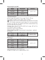
Changing Batteries
When the symbol appears on the screen, it indicates the batteries
are close to depletion and must be immediately replaced. To replace
the batteries, unfasten the screw at the rear of the casing and remove
the casing. Replace the at batteries with new ones of the same
type (9 V, type 1604 or 6F22) and make sure to observe the correct
polarity. Replace the rear casing.
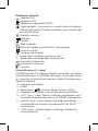
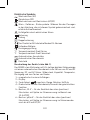
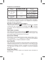
Electrical Symbols
Alternating current (AC)
Direct current (DC)
Alternating and direct current (AC/DC)
Warning symbol, hazard. Pay particular attention to sections of
the manual marked with this symbol.
Risk of injury by electric current
Fuse
Earthing
Double insulation
The product complies with applicable EU standards
Battery low
Continuity test
°C Celsius temperature unit
°F Fahrenheit temperature unit
Automatic switch-o
Automatic range
Data hold
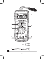
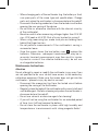
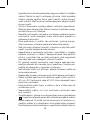
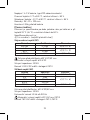
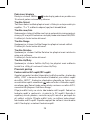
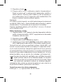
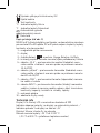
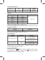
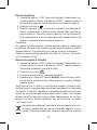
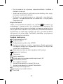
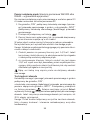
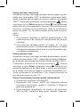
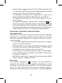
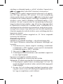
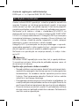
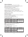
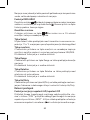
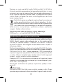
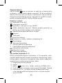
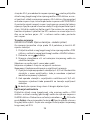
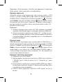
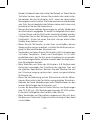
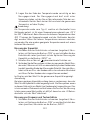
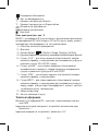
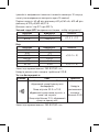
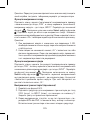
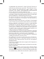
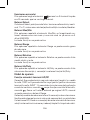
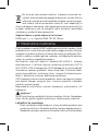
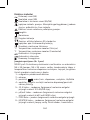
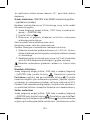
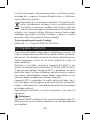
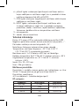
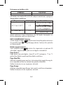
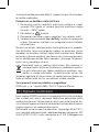
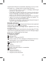
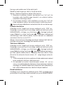
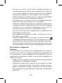
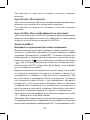
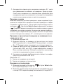
Description of the Device (see Fig. 1)
The M0430 is a 5 ¾ digit, digital multimeter with automatic range
adjustment for measuring DC and AC voltage, DC and AC current, re-
sistance, capacity and temperature, and testing continuity and diodes.
1 – magnetic loop for hanging
2 – screen
3 – Select, , max/min, Range, Relative, Hz/Duty
4 – Circular switch for changing measuring range/choosing a function
5 – 10 A socket – for the plug at the end of the red (positive)
tipped measuring conductor for measuring current in a
current range of 10 A AC/DC

7
6 – µA/mA socket – for the plug at the end of the red (positive)
tipped measuring conductor for measuring current in a
current range to up to 600 mA AC/DC
7 – COM socket – for the plug at the end of the black (negative)
tipped measuring conductor
8 – INPUT socket – for the plug at the end of the red (positive)
tipped measuring conductor for measuring voltage, resist-
ance, diodes, transistors, continuity, capacity, frequency and
duty cycle, temperature
9 – protective casing
10 – removing the probe cover
Technical Information
Screen: 5 ¾ digit LCD with a maximum displayable value of 5,999
Negative polarity indication: the screen automatically displays „-“
Overload indication: the screen displays „OL“
Reading frequency: approx. 2× a second
Temperature measurement range: -20°C to 1,000°C
(-20°C to 300°C with the enclosed thermocouple)
Power supply: 1× 9 V battery, type 6F22 or equivalent
Operating temperature: 0°C to 40°C, relative humidity < 80%
Storage temperature: -10°C to 50°C, relative humidity < 85%
Dimensions: 35 × 90 × 190 mm
Weight: 336 g including battery
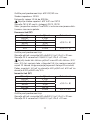
Measurement Accuracy
Accuracy is specied for the duration of one year after calibration
and at a temperature of 23°C (±5°C) and air humidity up to 80%.
Accuracy specications are:
±[(% of reading) + (lowest valid digits)]
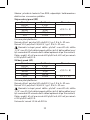
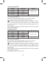
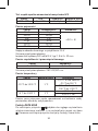
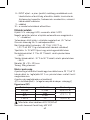
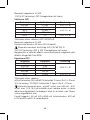
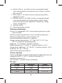
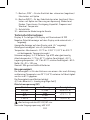
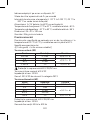
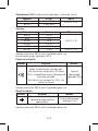
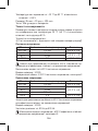
DC Voltage
Range Resolution Accuracy
600 mV 0.1 mV ±(0.8% + 5)
6 V 1 mV ±(0.8% + 3)
60 V 10 mV
1000 V 1 V ±(1% + 5)
Overload protection: 600 V DC/AC rms

8
Maximum input current: 600 V DC
Input impedance: 10 MΩ
Measure 1,000 V DC range in CAT II
AC Voltage
Range Resolution Accuracy
600 mV 0.1 mV ±(1.2% + 8)
6 V 1 mV
±(1.2% + 6)60 V 10 mV
600 V 100 mV
750 V 1 V ±(1.2% + 8)
Overload protection: 600 V DC/AC rms
Input impedance: 10 MΩ
Frequency range: 40 Hz to 400 Hz
Maximum input voltage: 600 V AC rms CAT III
Measure 750 V AC range in CAT II, CAT III
Response: True RMS, corresponding to a calibrated eective value
of a sine wave.
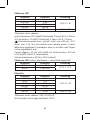
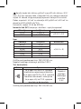
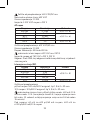
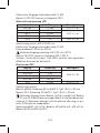
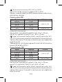
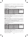
Direct Current (DC)
Range Resolution Accuracy
600 µA 0.1 µA
±(0.8% + 5)
6000 µA 1 µA
60 mA 10 µA
600 mA 100 µA
10 A 10 mA ±(1.5% + 3)
Overload protection:
µA/mA range: 500 mA/600 V fuse, type F, Ø 6.3 × 32 mm.
10 A range: 10 A/600 V fuse, type F, Ø 6.3 × 32 mm.
Maximum input current: µA/mA socket max. 600 mA; 10 A socket
max. 10 A (when measuring current above 5 A; the measurement
duration must be max. 10 seconds and further measurement may
only be made after 15 minutes)
Voltage drop: 60 mV for 600 µA/60 mA range, 600 mV for
6000 µA/600 mA/10 A range

9
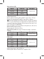
Alternating Current (AC)
Range Resolution Accuracy
600 µA 0.1 µA
±(1.5% + 8)
6000 µA 1 µA
60 mA 10 µA
600 mA 100 µA
10 A 10 mA ±(2% + 10)
Overload protection:
µA/mA range: 500 mA/600 V fuse, type F, Ø 6.3 × 32 mm.
10 A range: 10 A/600 V fuse, type F, Ø 6.3 × 32 mm.
Maximum input current: µA/mA socket max. 600 mA; 10 A socket
max. 10 A (when measuring current above 5 A; the measurement
duration must be max. 10 seconds and further measurement may
only be made after 15 minutes)
Voltage drop: 60 mV for 600 µA/60 mA range, 600 mV for
6000 µA/600 mA/10 A range
Frequency range: 40 Hz to 400 Hz
Alternating Current (AC) (measurement using clamps – optional
accessory)
Range Resolution Accuracy
200 A 1 mV/1 A ±(2.5% + 10)
600 A 1 mV/10 A
Resistance
Range Resolution Accuracy
600 Ω 0.1 Ω
±(1.5% + 3)
6 kΩ 1 Ω
60 kΩ 10 Ω
600 kΩ 100 Ω
6 MΩ 1 kΩ
60 MΩ 10 kΩ ±(1.5% + 5)
Overload protection: 250 V DC/AC rms
Voltage of an open circuit: approximately 0.25 V

10
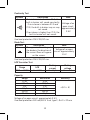
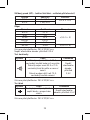
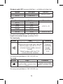
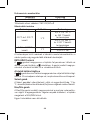
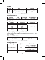
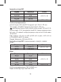
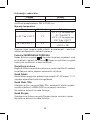
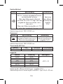
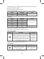
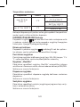
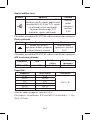
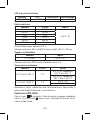
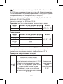
Continuity Test
Symbol Description Note
If resistance is lower than 30 Ω, the
built-in buzzer will sound constantly.
If resistance is between 30 Ω and
70 Ω; the built-in buzzer may or may
not sound.
If resistance is higher than 70 Ω, the
built-in buzzer will not sound.
Voltage of an
open circuit:
approximately
0.5 V
Overload protection: 250 V DC/AC rms
Diode Test
Symbol Description Note
The approximate voltage of
the diode in the direction of
the current ow will appear
on the screen.
Voltage of an open
circuit: approximately
1.5 V
Overload protection: 250 V DC/AC rms
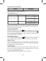
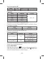
hFE Transistor Test
Range hFE Testing
current
Testing
voltage
PNP and NPN 0 ~ 1000 Ib ≈ 2 µA Vce ≈ 1 V
Capacity
Range Resolution Accuracy
10 nF 10 pF
±(8% + 5)
100 nF 100 pF
1 µF 1 nF
10 µF 10 nF
100 µF 100 nF
20 mF 10 µF
Voltage of an open circuit: approximately 0.5 V
Overload protection: 500 mA/600 V fuse, type F, Ø 6.3 × 32 mm

11
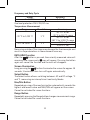
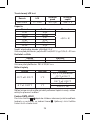
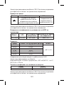
Frequency and Duty Cycle
Range Accuracy
0 ~ 10 MHz ±(1% + 5)
Overload protection: 250 V DC/AC rms
Temperature Measurement
Range Resolution Accuracy
-20°C to 1,000°C 1°C
±(1% + 4) for
-20°C to 150°C range
±(2% + 3) for
150°C to 1,000°C range
-4°F to 1,832°F 1°F ±(1% + 4)
±(1.5% + 15)
Measuring outside of the range may damage the thermocouple and
result in major deviations in measurement accuracy.
DATA HOLD function
After the button is pressed, the currently measured value will
remain on the screen and a icon will appear. Pressing the button
again will cancel the function and the icon will disappear.
Screen Illumination
Long-pressing the button illuminates the screen for approx. 15
seconds; illumination then turns o again automatically.
Select Button
The Select button allows switching between: AC and DC voltage, °C
and °F, measuring resistance/circuit continuity/diodes
Max/Min Button
Repeated pressing of the max/min button automatically records the
highest and lowest value and MAX/MIN will appear on the screen.
Cannot be activated for some functions.
Range Button
Repeatedly pressing the Range button changes measurement range.
Cannot be activated for some functions.

12
Relative Button
Repeatedly pressing the Relative button allows switching between
relative mode and auto mode.
Cannot be activated for some functions.
Hz/Duty Button
Repeatedly pressing the Hz/Duty button allows switching between
measuring frequency and duty cycle when the Hz/Duty function
is selected.
Operating Procedure
AC Voltage/DC Voltage Measurement
Connect the plug of the black (negative) tipped measuring conductor
into the COM socket and the plug of the red (positive) conductor for
measuring voltage into the INPUT socket. Turn the circular switch to
select the DC voltage function, marked as , or the AC voltage func-
tion, marked as . Range will be automatically set to AUTO mode;
you can switch to manual range selection using the Range button.
Place the measuring tips onto to spot you want to measure. The
voltage value and polarity (for DC voltage) will appear on the screen.
If you do not know the voltage range beforehand, set the largest
possible range and gradually reduce it as you measure. Connect the
measuring tips to the device or circuit where you will be measuring
voltage. Turn on the device you want to measure. The voltage value
will appear on the screen.
If „OL“ appears on the screen while in manual mode, set a higher
range.
Note: To prevent electric shock and damaging of the device, do not
connect the multimeter to voltage higher than 600 V AC/DC CAT III
and 750 V AC/1000 V DC CAT II.
Alternating Current/Direct Current Measurement
Note:
When measuring current up to 600 mA, connect the plug of the
black (negative) tipped measuring conductor into the COM socket
and the plug of the red (positive) conductor for measuring voltage
into the µA/mA socket. Switch to the function marked as or
and select the range.

13
Repeatedly pressing the Select button switches between measuring
direct current (DC) or alternating current (AC). When measuring cur-
rent up to 10 A, rst select the measuring range and then connect
the plug of the black (negative) tipped measuring conductor into the
COM socket and the plug of the red (positive) for measuring voltage
into the 10 A socket. If you do not know the current range beforehand,
leave the range setting on AUTO or set the highest range possible
and gradually reduce it as you measure. Connect the measuring
tips to the device or circuit where you will be measuring current.
Turn on the device you want to measure. The screen will display the
current value and polarity (for DC) relative to the red measuring tip.
If „OL“ appears on the screen while in manual mode, set a higher
range.
Current Measurement
(WH3303 or DM633 Measuring Clamp – Optional Accessory)
To measure alternating current over 10 A, it is necessary to use an
AC measuring clamp.
1. Connect the plug of the black (negative) tipped measuring
conductor into the COM socket and the plug of the red (positive)
conductor into the INPUT socket.
2. Switch to the function.
3. Measurement with clamps is done by gripping the measured
conductor with the centre of the clamp.
Only one conductor can be measured at a time.
The measured current value will appear on the screen.
Note: Unifying deviation in measurement sensitivity
1. The sensitivity of measurement using the clamp is 1 A/1 mV. If
you are using a clamp with this sensitivity, then the listed value
is identical to the measured value.
2. When using a clamp with sensitivity other than 1 A/1 mV, the
measured value should be multiplied based on the sensitivity
of the clamp.
Do not touch the measured circuit with your hand or other part
of the body.

14
Continuity Test
Connect the plug of the black (negative) tipped measuring conductor
into the COM socket and the plug of the red (positive) conductor for
measuring voltage into the INPUT socket. Switch to the function
marked with . Press the Select button repeatedly to select the
function. Connect the measuring tips to the circuit you want to
measure. The buzzer will sound if the resistance of the measured
circuit is lower than 30 Ω.
Note: Before testing, disconnect all power supply from the circuit you
want to test and thoroughly discharge all capacitors.
Resistance Measurement
Connect the plug of the black (negative) tipped measuring conductor
into the COM socket and the plug of the red (positive) conductor for
measuring voltage into the INPUT socket. Switch to the function
marked with . Press the Select button repeatedly to select
the function. Connect the measuring tips to the object you want
to measure (resistor). The measured resistance value will appear
on the screen. If the „OL“ symbol appears on the screen, switch to
a higher range.
Note:
1. When measuring resistances higher than 1 MΩ, it is necessary
to wait a few seconds before the measured value stabilizes.
2. If the circuit is open, the „OL“ symbol will appear, same as when
the measuring range is exceeded. Before measuring resistance,
make sure that the measured object is disconnected from power
supply and all its capacitors are fully discharged.
Diode Measurement
Connect the plug of the black (negative) measuring conductor into
the COM socket and the plug of the red (positive) measuring tip for
measuring diodes into the INPUT socket. Switch to the function
marked with . Press the Select button repeatedly to select the
function. Connect the red measuring tip onto the diode‘s anode
and the black measuring tip onto the diode‘s cathode. Approximate
voltage in the direction of the ow of current will appear on the
screen. „OL“ will appear on the screen if the polarity is reversed.

15
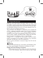
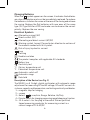
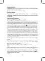
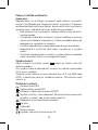
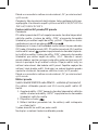
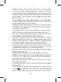
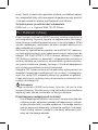
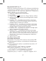
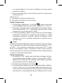
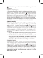
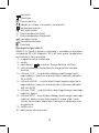
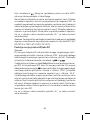
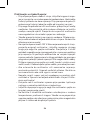
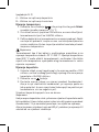
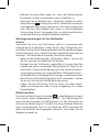
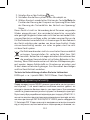
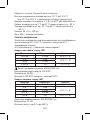
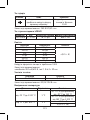
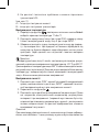
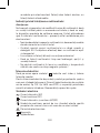
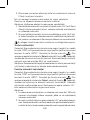
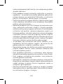
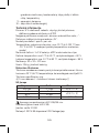
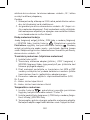
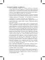
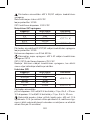
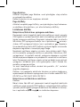
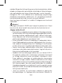
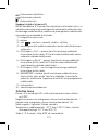
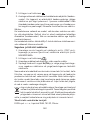
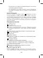
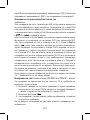
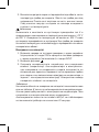
Transistor Measurement (Amplication)
1. Switch to the hFE function.
2. Connect an adapter for measuring transistors into the COM
(minus) socket and the INPUT (plus) socket according to gure
2. make sure the connection is correct!
3. Before you measure, determine whether the transistor has an
NPN or PNP junction and identify the base, emitter and collec-
tor. Connect the outlets from the transistor into the marked
openings in the adapter.
4. The approximate transistor amplication factor (hFE) will appear
on the screen.
(see Fig. 2)
A – Socket for testing capacity
B – Socket for testing transistors
Temperature Measurement
1. Switch to the function and repeatedly press the Select
button to choose between measuring in °C or °F.
2. Connect the black plug (minus) to the COM socket and the red
plug (plus) of the type K thermocouple to the INPUT socket.
3. Carefully touch the end of the thermocouple onto the measured
object. The object must not be live; be mindful of any rotating
parts on various devices. The screen will show the measured
temperature after a few moments.
Note:
The type K thermocouple included with the multimeter is designed
for measuring temperatures between -20°C and 300°C. Measuring
temperatures above 300°C may cause damage to the thermocouple
and the multimeter! If you want to measure higher temperatures,
use a dierent thermocouple with a higher measurement range!
Capacity Measurement
1. Connect the plug of the black (negative) tipped measuring
conductor into the COM socket and the plug of the red (positive)
measuring tip for measuring capacity into the INPUT socket.
2. Switch to the function.

16
3. Place the measuring tips onto the measured object (capacitor).
If it is e.g. an electrolytic capacitor, make sure to observe correct
polarity during measurement. (the red measuring cable should
be connected to the capacitor‘s positive pole, the black to the
negative pole).
The capacity value will appear on the screen.
Note:
When the capacity range is low, the displayed capacity value may
be unstable. In that case, the measuring tips were not connected
to the object (capacitor). This is normal behaviour and does not
aect measurement.
If the measured value is over 600 μF, it takes at least 10 seconds
for the value to stabilise.
Frequency and Duty Cycle Measurement
1. Connect the plug of the black (negative) tipped measuring
conductor into the COM socket and the plug of the red (positive)
measuring tip into the INPUT socket.
2. Switch to the function.
3. Connect the measuring tips to the object you want to measure.
4. Repeatedly press the Hz/Duty button to select voltage/cur-
rent frequency measurement or voltage/current duty cycle
measurement.
This device is not intended for use by persons (including children)
whose physical, sensory or mental disability or lack of experience or
knowledge prevents them from using it safely. Such persons should
be instructed in how to use the device and should be supervised
by a person responsible for their safety. Children must always be
supervised to ensure they do not play with the device.
Do not dispose with domestic waste. Use special collection
points for sorted waste. Contact local authorities for informa-
tion about collection points. If the electronic devices would be
disposed on landll, dangerous substances may reach ground-
water and subsequently food chain, where it could aect human health.
You can request technical assistance from the supplier:
EMOS spol. s r. o., Lipnická 2844, 750 02, Přerov

17
CZ | Digitální multimetr
Než začnete M0430 používat, pečlivě si přečtěte tento návod k
obsluze. Jsou v něm zvýrazněny zvláště důležité pasáže, které po-
jednávají o zásadách bezpečnosti práce s tímto přístrojem. Zabráníte
tak možnému úrazu elektrickým proudem nebo poškození přístroje.
Multimetr byl navržen v souladu s normou EN 61010-1 vztahující se
na elektronické měřicí přístroje spadající do kategorie CAT III 600 V/
CAT II 1000 V, úroveň znečištění 2.
Kategorie CAT III je určena k měření obvodů z vybavení napájeného
pevnou instalací, jako relé, zásuvky, rozvodné panely, napáječe a
krátké větvící obvody a osvětlovací systémy ve velkých budovách.
Kategorie CAT II je určena k měření prováděných na obvodech přímo
připojených k instalaci nízkého napětí (např. domácích spotřebičů,
přenosných nástrojů a podobného vybavení).
Nepoužívejte multimetr k měření rozsahů spadajících do kategorie IV!
Varování
Používejte multimetr M0430 pouze tak, jak je specikováno níže.
Jinak může dojít k poškození přístroje nebo Vašeho zdraví.
Dbejte následujících instrukcí:
• Dříve, než provedete měření odporu, diod nebo proudu, odpojte
obvody od zdrojů energie a vybijte vysokonapěťové kondenzátory.
Pro dané měření použijte správnou volbu funkce. Před změnou
rozsahu (funkce) odpojte vodiče od měřeného obvodu.
• Než začnete multimetr používat, pozorně zkontrolujte, zda
není přístroj poškozen. Pokud naleznete na těle přístroje zjevné
poškození, neprovádějte žádná měření! Zkontrolujte, není-li
povrch multimetru poškrábaný a nejsou-li boční spoje rozklížené.
• Zkontrolujte také izolaci na měřicích sondách. Při poškození
izolace hrozí nebezpečí úrazu elektrickým proudem. Poškozené
měřicí sondy nepoužívejte!
• Neměřte napětí vyšší jak 1000 V! Budete-li měřit proud, zkont-
rolujte pojistku multimetru a vypněte napájení obvodu předtím,
než k němu multimetr připojíte. Před měřením se přesvědčte,
že je kruhový přepínač rozsahu měření ve správné poloze. V
žádném případě neprovádějte žádné změny v měřícím rozsahu

18
(pootáčením kruhového přepínače programů měření) v průběhu
měření! Mohlo by dojít k poškození přístroje. Když provádíte
měření, připojte nejdříve černý vodič (sondu), potom červený
vodič (sondu). Když testovací vodiče odpojujete, odpojte nejdřív
červený vodič.
• Zjistíte-li abnormální výsledky měření, multimetr nepoužívejte.
Může být přerušena pojistka. Pokud si nejste jisti příčinou závady,
kontaktujte servisní středisko.
• Neměřte vyšší napětí, než jaké je vyznačeno na předním panelu
multimetru. Hrozí nebezpečí úrazu elektrickým proudem a
poškození multimetru!
• Před používáním si ověřte, zda multimetr správně pracuje.
Otestujte obvod, u kterého znáte jeho elektrické veličiny.
• Než multimetr připojíte k obvodu, u kterého se chystáte měřit
napětí, vypněte napájení daného obvodu.
• Nepoužívejte a neskladujte multimetr v prostředích s vysokou
teplotou, prašností a vlhkostí. Nedoporučujeme také používat
přístroj v prostředí, kde se může vyskytovat silné magnetické
pole nebo kde hrozí nebezpečí výbuchu či požáru.
• Při výměně součásti multimetru (např. baterie nebo pojistka),
použijte náhradní díly stejného typu a specikací. Výměnu pro-
vádějte při odpojeném a vypnutém multimetru.
• Než otevřete zadní kryt přístroje, odpojte testovací vodiče od
testovaného obvodu.
• Nepozměňujte nebo nijak neupravujte vnitřní obvody multimetru!
• Dbejte zvýšené opatrnosti při měřeních napětí vyšších jak 30 V
AC rms, 42 V špičkových nebo 60 V DC. Hrozí nebezpečí úrazu
elektrickým proudem!
• Když používáte měřící hroty, ujistěte se, že je svíráte rukou až
za zábranou prstů.
• Neprovádějte měření, je-li kryt multimetru odstraněn nebo
je-li uvolněný.
• Vyměňte baterii, jakmile se na displeji objeví ikona vybité baterie
. V opačném případě mohou být následně provedená měření
budou nepřesná. To může vést ke zkresleným či falešným vý-
sledkům měření a k následnému úrazu elektrickým proudem!
Používejte pouze alkalické baterie, nepoužívejte nabíjecí baterie.

19
Pokyny k údržbě multimetru
Upozornění:
Nepokoušejte se multimetr opravovat nebo jakkoliv upravovat,
nejste-li kvalikováni pro takovouto činnost a nemáte-li k dispozici
potřebné kalibrační přístroje. Dbejte, aby do vnitřní části multimetru
nevnikla voda – zabráníte tak úrazu elektrickým proudem!
• Než otevřete kryt multimetru, odpojte měřící hroty od testo-
vaného obvodu.
• Pravidelně čistěte tělo multimetru vlhkým hadříkem a jemným
mycím prostředkem (saponátem). Čištění provádějte pouze při
odpojeném a vypnutém multimetru.
• K čištění nepoužívejte rozpouštědla nebo brusné prostředky!
• Nepoužíváte-li multimetr delší dobu, vypněte jej a vyjměte
baterii.
• Multimetr neuchovávejte v místech s vysokou vlhkostí a teplotou
nebo v prostředí, kde je silné magnetické pole!
Výměna baterií
Když se objeví na displeji symbol , baterie je slabá a musí být
ihned vyměněna.
Pro výměnu baterie odšroubujte šroubky ze zadního bateriového
krytu a kryt sundejte.
Vyměňte vybité baterie za nové stejného typu (9 V, typ 1604 nebo
6F22) a dodržujte polaritu vkládané baterie. Přišroubujte zpět
zadní kryt.
Elektrické symboly
Střídavý proud (AC)
Stejnosměrný proud (DC)
Střídavý a stejnosměrný proud (AC/DC)
Symbol výstrahy, rizika nebezpečí. Věnujte zvýšenou pozornost
pasážím v návodu, kde je tato značka použita.
Nebezpečí úrazu elektrickým proudem
Pojistka
Uzemnění
Dvojitá izolace
Výrobek splňuje příslušné normy EU

20
Vybitá baterie
Test kontinuity
°C Jednotka teploty Celsia
°F Jednotka teploty Fahrenheit
Automatické vypnutí
Automatický rozsah
Data hold
Popis přístroje (viz obr. 1)
M0430 je 5 ¾ číselný digitální multimetr s automatickým rozsahem
pro měření DC a AC napětí, DC a AC proudu, odporu, kapacity, teploty,
kontinuity a testování diod.
1 – magnetické poutko na zavěšení
2 – displej
3 – tlačítko Select, , max/min, Range, Relative, Hz/Duty
4 – kruhový přepínač rozsahu měření/výběr požadované funkce
5 – zdířka „10 A“ – pro koncovku červeného (kladného) měřícího
vodiče s hrotem k měření proudu na proudovém rozsahu 10 A
AC/DC
6 – zdířka „µA/mA“ – pro koncovku červeného (kladného) měřící-
ho vodiče s hrotem k měření proudu na proudovém rozsahu
do 600 mA AC/DC
7 – zdířka „COM“ – pro koncovku černého (záporného) měřícího
vodiče s hrotem
8 – zdířka INPUT – pro koncovku červeného (kladný) měřícího
vodiče s hrotem k měření napětí, odporu, diod, tranzistorů,
kontinuity, kapacity, kmitočtu a střídy, teploty
9 – ochranné pouzdro
10 – sejmutí krytky sondy
Technické info
Displej: 5 ¾ číselný LCD s maximální hodnotou 5999
Indikace záporné polarity: na displeji se automaticky zobrazí „-“
Indikace přesahu: na displeji se zobrazí „OL“
Rychlost čtení: zhruba 2× za sekundu
Rozsah měření teploty: -20°C až 1000°C (-20°C až 300°C s při-
loženou teplotní sondou)
Pagina se încarcă...
Pagina se încarcă...
Pagina se încarcă...
Pagina se încarcă...
Pagina se încarcă...
Pagina se încarcă...
Pagina se încarcă...
Pagina se încarcă...
Pagina se încarcă...
Pagina se încarcă...
Pagina se încarcă...
Pagina se încarcă...
Pagina se încarcă...
Pagina se încarcă...
Pagina se încarcă...
Pagina se încarcă...
Pagina se încarcă...
Pagina se încarcă...
Pagina se încarcă...
Pagina se încarcă...
Pagina se încarcă...
Pagina se încarcă...
Pagina se încarcă...
Pagina se încarcă...
Pagina se încarcă...
Pagina se încarcă...
Pagina se încarcă...
Pagina se încarcă...
Pagina se încarcă...
Pagina se încarcă...
Pagina se încarcă...
Pagina se încarcă...
Pagina se încarcă...
Pagina se încarcă...
Pagina se încarcă...
Pagina se încarcă...
Pagina se încarcă...
Pagina se încarcă...
Pagina se încarcă...
Pagina se încarcă...
Pagina se încarcă...
Pagina se încarcă...
Pagina se încarcă...
Pagina se încarcă...
Pagina se încarcă...
Pagina se încarcă...
Pagina se încarcă...
Pagina se încarcă...
Pagina se încarcă...
Pagina se încarcă...
Pagina se încarcă...
Pagina se încarcă...
Pagina se încarcă...
Pagina se încarcă...
Pagina se încarcă...
Pagina se încarcă...
Pagina se încarcă...
Pagina se încarcă...
Pagina se încarcă...
Pagina se încarcă...
Pagina se încarcă...
Pagina se încarcă...
Pagina se încarcă...
Pagina se încarcă...
Pagina se încarcă...
Pagina se încarcă...
Pagina se încarcă...
Pagina se încarcă...
Pagina se încarcă...
Pagina se încarcă...
Pagina se încarcă...
Pagina se încarcă...
Pagina se încarcă...
Pagina se încarcă...
Pagina se încarcă...
Pagina se încarcă...
Pagina se încarcă...
Pagina se încarcă...
Pagina se încarcă...
Pagina se încarcă...
Pagina se încarcă...
Pagina se încarcă...
Pagina se încarcă...
Pagina se încarcă...
Pagina se încarcă...
Pagina se încarcă...
Pagina se încarcă...
Pagina se încarcă...
Pagina se încarcă...
Pagina se încarcă...
Pagina se încarcă...
Pagina se încarcă...
Pagina se încarcă...
Pagina se încarcă...
Pagina se încarcă...
Pagina se încarcă...
Pagina se încarcă...
Pagina se încarcă...
Pagina se încarcă...
Pagina se încarcă...
Pagina se încarcă...
Pagina se încarcă...
Pagina se încarcă...
Pagina se încarcă...
Pagina se încarcă...
Pagina se încarcă...
Pagina se încarcă...
Pagina se încarcă...
Pagina se încarcă...
Pagina se încarcă...
Pagina se încarcă...
Pagina se încarcă...
Pagina se încarcă...
Pagina se încarcă...
Pagina se încarcă...
Pagina se încarcă...
Pagina se încarcă...
Pagina se încarcă...
Pagina se încarcă...
Pagina se încarcă...
Pagina se încarcă...
Pagina se încarcă...
Pagina se încarcă...
Pagina se încarcă...
Pagina se încarcă...
Pagina se încarcă...
Pagina se încarcă...
Pagina se încarcă...
Pagina se încarcă...
Pagina se încarcă...
Pagina se încarcă...
Pagina se încarcă...
Pagina se încarcă...
Pagina se încarcă...
Pagina se încarcă...
Pagina se încarcă...
Pagina se încarcă...
Pagina se încarcă...
Pagina se încarcă...
Pagina se încarcă...
Pagina se încarcă...
Pagina se încarcă...
Pagina se încarcă...
Pagina se încarcă...
Pagina se încarcă...
Pagina se încarcă...
Pagina se încarcă...
Pagina se încarcă...
Pagina se încarcă...
Pagina se încarcă...
Pagina se încarcă...
Pagina se încarcă...
Pagina se încarcă...
Pagina se încarcă...
Pagina se încarcă...
Pagina se încarcă...
Pagina se încarcă...
Pagina se încarcă...
Pagina se încarcă...
Pagina se încarcă...
Pagina se încarcă...
Pagina se încarcă...
Pagina se încarcă...
Pagina se încarcă...
Pagina se încarcă...
Pagina se încarcă...
Pagina se încarcă...
Pagina se încarcă...
Pagina se încarcă...
Pagina se încarcă...
Pagina se încarcă...
Pagina se încarcă...
Pagina se încarcă...
Pagina se încarcă...
Pagina se încarcă...
Pagina se încarcă...
Pagina se încarcă...
Pagina se încarcă...
Pagina se încarcă...
Pagina se încarcă...
-
 1
1
-
 2
2
-
 3
3
-
 4
4
-
 5
5
-
 6
6
-
 7
7
-
 8
8
-
 9
9
-
 10
10
-
 11
11
-
 12
12
-
 13
13
-
 14
14
-
 15
15
-
 16
16
-
 17
17
-
 18
18
-
 19
19
-
 20
20
-
 21
21
-
 22
22
-
 23
23
-
 24
24
-
 25
25
-
 26
26
-
 27
27
-
 28
28
-
 29
29
-
 30
30
-
 31
31
-
 32
32
-
 33
33
-
 34
34
-
 35
35
-
 36
36
-
 37
37
-
 38
38
-
 39
39
-
 40
40
-
 41
41
-
 42
42
-
 43
43
-
 44
44
-
 45
45
-
 46
46
-
 47
47
-
 48
48
-
 49
49
-
 50
50
-
 51
51
-
 52
52
-
 53
53
-
 54
54
-
 55
55
-
 56
56
-
 57
57
-
 58
58
-
 59
59
-
 60
60
-
 61
61
-
 62
62
-
 63
63
-
 64
64
-
 65
65
-
 66
66
-
 67
67
-
 68
68
-
 69
69
-
 70
70
-
 71
71
-
 72
72
-
 73
73
-
 74
74
-
 75
75
-
 76
76
-
 77
77
-
 78
78
-
 79
79
-
 80
80
-
 81
81
-
 82
82
-
 83
83
-
 84
84
-
 85
85
-
 86
86
-
 87
87
-
 88
88
-
 89
89
-
 90
90
-
 91
91
-
 92
92
-
 93
93
-
 94
94
-
 95
95
-
 96
96
-
 97
97
-
 98
98
-
 99
99
-
 100
100
-
 101
101
-
 102
102
-
 103
103
-
 104
104
-
 105
105
-
 106
106
-
 107
107
-
 108
108
-
 109
109
-
 110
110
-
 111
111
-
 112
112
-
 113
113
-
 114
114
-
 115
115
-
 116
116
-
 117
117
-
 118
118
-
 119
119
-
 120
120
-
 121
121
-
 122
122
-
 123
123
-
 124
124
-
 125
125
-
 126
126
-
 127
127
-
 128
128
-
 129
129
-
 130
130
-
 131
131
-
 132
132
-
 133
133
-
 134
134
-
 135
135
-
 136
136
-
 137
137
-
 138
138
-
 139
139
-
 140
140
-
 141
141
-
 142
142
-
 143
143
-
 144
144
-
 145
145
-
 146
146
-
 147
147
-
 148
148
-
 149
149
-
 150
150
-
 151
151
-
 152
152
-
 153
153
-
 154
154
-
 155
155
-
 156
156
-
 157
157
-
 158
158
-
 159
159
-
 160
160
-
 161
161
-
 162
162
-
 163
163
-
 164
164
-
 165
165
-
 166
166
-
 167
167
-
 168
168
-
 169
169
-
 170
170
-
 171
171
-
 172
172
-
 173
173
-
 174
174
-
 175
175
-
 176
176
-
 177
177
-
 178
178
-
 179
179
-
 180
180
-
 181
181
-
 182
182
-
 183
183
-
 184
184
-
 185
185
-
 186
186
-
 187
187
-
 188
188
-
 189
189
-
 190
190
-
 191
191
-
 192
192
-
 193
193
-
 194
194
-
 195
195
-
 196
196
-
 197
197
-
 198
198
-
 199
199
-
 200
200


în alte limbi
- slovenčina: Emos M0430 Návod na používanie
- eesti: Emos M0430 Kasutusjuhend
Lucrări înrudite
Alte documente
-
Defort DMM-600 Manualul proprietarului
-
-
Benning MM4 Instrucțiuni de utilizare
-
Facom 714A Manualul proprietarului
-
Somogyi SMA MAS 830 Manual de utilizare
-
-
Stanley FMHT0-77421 Manual de utilizare
-
-
-
Hama 00223565 Manual de utilizare