
1
GB
Auto Feed Screwdriver INSTRUCTION MANUAL
UA
PL
Wkrtarka z automatycznym podajnikiem
INSTRUKCJA OBSUGI
RO
Main de înurubat cu alimentare automat
MANUAL DE INSTRUCIUNI
DE
Magazinschnellschrauber BEDIENUNGSANLEITUNG
HU
Önetet csavarbehajtó HASZNÁLATI KÉZIKÖNYV
SK
Skrutkova s automatickým podávaním
NÁVOD NA OBSLUHU
CZ
Šroubovák se zásobníkem NÁVOD K OBSLUZE
6833
6834
6836

2
1
2
1 002629
1
2 002636
1
3 002648
1
2
4 002656
12
3
5 002657
1
2
3
4
6 002663
A
B
1
2
3
5mm
7 004177
1
2
3
8 002666

3
1
9 002667
10 002668
1
11 002669
1
12 002671
13 002676
1
2
15mm
14 004186
1
15 001145
1
2
16 002686

4
ENGLISH
Explanation of general view
1-1. Lock button
1-2. Switch trigger
2-1. Reversing switch
3-1. Hook
4-1. Casing
4-2. Thumb screw
5-1. Dust cover
5-2. Plane bearing
5-3. Bit
6-1. Lever
6-2. Stopper base
6-3. Plate
6-4. Casing
7-1. Stopper base
7-2. Casing
7-3. Adjusting knob
8-1. Feeder box
8-2. Screw strip
8-3. Screw guide
9-1. Driving position
11-1. Reverse button
12-1. Extension handle
14-1. Wall
14-2. Stopper base
15-1. Limit mark
16-1. Screwdriver
16-2. Brush holder cap
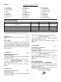
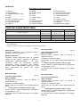
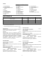
SPECIFICATIONS
Model 6833 6834 6836
Screw strip
4 mm
x 25 mm - 41 mm
4 mm
x 25 mm - 57 mm
4 mm
x 25 mm - 41 mm
No load speed (min
-1
) 4,700 2,800 6,000
Overall length 364 mm 396 mm 364 mm
Net weight 1.9 kg 1.9 kg 1.9 kg
Safety class /II
• Due to our continuing programme of research and development, the specifications herein are subject to change without notice.
• Note: Specifications may differ from country to country.
ENE033-1
Intended use
The tool is intended for screw driving in wood, metal and
plastic.
ENF002-1
Power supply
The tool should be connected only to a power supply of
the same voltage as indicated on the nameplate, and
can only be operated on single-phase AC supply. They
are double-insulated in accordance with European
Standard and can, therefore, also be used from sockets
without earth wire.
For Model 6833
ENG003-2
For European countries only
Noise and Vibration
The typical A-weighted sound pressure level is 80 dB (A).
Uncertainty is 3 dB(A).
The noise level under working may exceed 85 dB (A).
Wear ear protection.
The typical weighted root mean square acceleration
value is not more than 2.5 m/s
2
.
These values have been obtained according to
EN60745.
For Model 6834
ENG003-2
For European countries only
Noise and Vibration
The typical A-weighted sound pressure level is 81 dB (A).
Uncertainty is 3 dB(A).
The noise level under working may exceed 85 dB (A).
Wear ear protection.
The typical weighted root mean square acceleration
value is not more than 2.5 m/s
2
.
These values have been obtained according to
EN60745.
For Model 6836
ENG003-2
For European countries only
Noise and Vibration
The typical A-weighted sound pressure level is 83 dB (A).
Uncertainty is 3 dB(A).
The noise level under working may exceed 85 dB (A).
Wear ear protection.
The typical weighted root mean square acceleration
value is not more than 2.5 m/s
2
.
These values have been obtained according to
EN60745.
ENH101-5
Model; 6833,6834,6836
EC-DECLARATION OF CONFORMITY
We declare under our sole responsibility that this
product is in compliance with the following standards of
standardized documents;
EN60745, EN55014, EN61000 in accordance with
Council Directives, 89/336/EEC, 98/37/EC.
Yasuhiko Kanzaki CE2005
000087

5
Director
MAKITA INTERNATIONAL EUROPE LTD.
Michigan Drive, Tongwell, Milton Keynes, Bucks MK15
8JD, ENGLAND
Responsible manufacturer:
Makita Corporation Anjo Aichi Japan
GEB017-1
SPECIFIC SAFETY RULES
DO NOT let comfort or familiarity with product
(gained from repeated use) replace strict adherence
to screwdriver safety rules. If you use this power
tool unsafely or incorrectly, you can suffer serious
personal injury.
1. Hold power tools by insulated gripping
surfaces when performing an operation where
the cutting tool may contact hidden wiring or
its own cord. Contact with a "live" wire will make
exposed metal parts of the tool "live" and shock
the operator.
2. Always be sure you have a firm footing.
Be sure no one is below when using the tool in
high locations.
3. Hold the tool firmly.
4. Keep hands away from rotating parts.
5. Do not touch the bit or the workpiece
immediately after operation; they may be
extremely hot and could burn your skin.
SAVE THESE INSTRUCTIONS.
WARNING:
MISUSE or failure to follow the safety rules stated in
this instruction manual may cause serious personal
injury.
FUNCTIONAL DESCRIPTION
CAUTION:
• Always be sure that the tool is switched off and
unplugged before adjusting or checking function on
the tool.
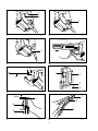
Switch action
Fig.1
CAUTION:
• Before plugging in the tool, always check to see
that the switch trigger actuates properly and
returns to the "OFF" position when released.
To s tart t he tool, s im ply p ul l t he s wi tch t ri gg er. R el ea se
the switch trigger to stop.
For continuous operation, pull the switch trigger and
then push in the lock button.
To stop th e t oo l f rom the lo cked position, pull the switch
trigger fully, then release it.
Reversing switch action
Fig.2
CAUTION:
• Always check the direction of rotation before
operation.
• Use the reversing switch only after the tool comes
to a complete stop. Changing the direction of
rotation before the tool stops may damage the tool.
This tool has a reversing switch to change the direction
of rotation. Press the upper side (FWD side) of the
reversing switch for clockwise rotation or the lower side
(REV side) of the reversing switch for counterclockwise
rotation.
Hook
Fig.3
The hook is convenient for hooking the tool to your belt.
It can be installed on either side of the tool. To remove it,
pull it out in the direction of the arrow while raising. To
install the hook, push it down until it "clicks" into place on
the tool.
ASSEMBLY
CAUTION:
• Always be sure that the tool is switched off and
unplugged before carrying out any work on the
tool.
Installing or removing the bit
Loosen the thumb screws which secure the casing. Pull
out the casing in the direction of the arrow.
Fig.4
Press the dust cover toward the plain bearing and pull
out the bit. If the dust cover cannot be moved as far as
the plain bearing, try it again after turning the bit slightly.
To i ns tall t he bit, i nsert i t int o the sock et while t ur ni ng i t
slightly. After installing, always make sure that the bit is
securely held in place by trying to pull it out.
Fig.5
Setting for desired screw length
Fig.6
There are 3 (for Model 6833 & 6836) or 5 (for Model
6834) positive-lock screw length settings. To obtain the
desired setting, pull out the stopper base while
depressing the lever until you see the number of the
desired screw length (indicated on the plate) appear to
rest on the very top edge of the casing. See the table
below for the relation between the number indicated on
the plate and the respective screw length ranges.

6
25/28 25 mm - 28 mm
32 28 mm - 35 mm
40 35 mm - 41 mm
* 51 41 mm - 51 mm
* 57 51 mm - 57 mm
Number indicated on the plate Screw length range
(Note) * for Model 6834 only
006404
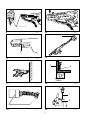
Adjusting the driving depth
Fig.7
Depress the stopper base as far as it will go. While
keeping it in this position, turn the adjusting knob until
the bit tip projects approx. 5 mm from the stopper base.
Drive a trial screw. If the screw head projects above the
surface of the workpiece, turn the adjusting knob in the
"A" direction; if the screw head is counter-sunk, turn the
adjusting knob in the "B" direction.
Installing screw strip
Fig.8
Fig.9
Insert the screw strip through the screw guide. Then
insert it through the feeder box until the first screw
reaches the position next to the driving position.
Removing screw strip
Fig.10
Fig.11
To re mo ve the s cr ew stri p, jus t p ul l it o ut in the di re ct io n
of the arrow. If you depress the reverse button, you can
pull out the screw strip in the reverse direction of the
arrow.
Extension handle (optional accessory)
Fig.12
Use of extension handle allows you to drive screws into
floors while standing.
OPERATION
Driving operation
Fig.13
Switch on the tool by pressing the switch trigger and at
the same time pushing the lock button. Hold the tool
squarely against the workpiece and apply forward
pressure to the tool. The screw will be automatically
carried to the driving position and driven into the
workpiece.
NOTE:
• Do not fire the tool without screws. This will
damage the workpiece.
• If the feeder box becomes sluggish in operation,
spray car wax (spray type wax) on its sliding
surfaces. Never lubricate it.
Driving in corner
Fig.14
This tool can be used to drive at a position 15 mm away
from the wall as shown in the figure.
CAUTION:
• Driving at a position closer than 15 mm to the wall
or driving with the stopper base in contact with the
wall may damage the screw heads and cause wear
on the bit. This may also lead to poor fastening of
screws and malfunction of the tool.
MAINTENANCE
CAUTION:
• Always be sure that the tool is switched off and
unplugged before attempting to perform inspection
or maintenance.
Replacing carbon brushes
Fig.15
Remove and check the carbon brushes regularly.
Replace when they wear down to the limit mark. Keep
the carbon brushes clean and free to slip in the holders.
Both carbon brushes should be replaced at the same
time. Use only identical carbon brushes.
Use a screwdriver to remove the brush holder caps.
Take out the wor n c ar bo n b rushes, inser t t he new ones
and secure the brush holder caps.
Fig.16
To mainta in pro du ct S AF ET Y an d RE LI AB ILITY, rep airs,
any other maintenance or adjustment should be
performed by Makita Authorized Service Centers,
always using Makita replacement parts.
ACCESSORIES
CAUTION:
• These accessories or attachments are
recommended for use with your Makita tool
specified in this manual. The use of any other
accessories or attachments might present a risk of
injury to persons. Only use accessory or
attachment for its stated purpose.
If you need any assistance for more details regarding
these accessories, ask your local Makita Service Center.
• Phillips bit
• Drywall screw strips
• Extension handle
• Plastic carrying case

7
1-1.
1-2.
2-1.
3-1.
4-1.
4-2.
5-1.
5-2.
5-3.
6-1.
6-2.
6-3.
6-4.
7-1.
7-2.
7-3.
8-1.
8-2.
8-3.
9-1.
11-1.
12-1.
14-1.
14-2.
15-1.
16-1.
16-2.
6833 6834 6836
4
x 25 - 41
4
x 25 - 57
4
x 25 - 41
(
-1
) 4700 2800 6000
364 396 364
1,9 1,9 1,9
/II
• , ,
.
• . .
ENE033-1
, .
ENF002-1
, ,
,
.
, ,
.
6833
ENG003-2
80 (A).
3 (A).
85
(A).
.
2,5 /
2
.
EN60745.
6834
ENG003-2
81 (A).
3 (A).
85
(A).
.
2,5 /
2
.
EN60745.
6836
ENG003-2
83 (A).
3 (A).
85
(A).
.
2,5 /
2
.
EN60745.

8
ENH101-5
; 6833,6834,6836
,
;
EN60745, EN55014, EN61000
89/336/EEC, 98/37/EC.
CE2005
000087
.
-, , -,
MK15 8JD,
:
GEB017-1
(
),
.
,
.
1. ,
,
.
.
2. .
, .
3. .
4.
,
.
5.
,
.
:
,
,
.
:
•
, ,
.
.
Fig.1
:
•
' ,
"".
,
. - .
,
.
,
.
-.
Fig.2
:
•
.
•
.
.
.
( "FWD")
, ( "REV")
.
Fig.3
. -
. , ,
, .
, .
.
:
• ,
, ,
.

9
, .
,
.
Fig.4
, .
, ,
.
, .
,
, .
Fig.5
Fig.6
3 ( 6833 6836) 5 (
6834)
.
,
, '
( ).
- .
.
25/28 25 мм - 28 мм
32 28 мм - 35 мм
40 35 мм - 41 мм
* 51 41 мм - 51 мм
* 57 51 мм - 57 мм
Номер вказаний на табличці Діапазон довжини гвинта
(Примітка) * тільки для моделі 6834
006404
Fig.7
.
,
5 .
.
,
"", ,
"".
Fig.8
Fig.9
.
,
.
Fig.10
Fig.11
.
,
.
(
)
Fig.12
.
Fig.13
, ,
.
.
.
:
• .
.
•
,
() .
.
.
Fig.14
15 ,
.
:
• , 15
, ,
,
.
.

10
:
• , ,
, ,
.
Fig.15
.
, .
.
.
.
. ,
.
Fig.16
,
, ,
"",
"".
:
•
"",
.
.
.
,
"".
• Phillips
•
•
•

11
POLSKI
Objanienia do widoku ogólnego
1-1. Przycisk blokujcy
1-2. Spust przecznika
2-1. Przecznik zmiany kierunku
obrotów
3-1. Hak
4-1. Obudowa
4-2. ruba skrzydekowa
5-1. Osona przeciwpyowa
5-2. oysko paskie
5-3. Wierto
6-1. Dwignia
6-2. Podstawa oporowa
6-3. Pytka
6-4. Obudowa
7-1. Podstawa oporowa
7-2. Obudowa
7-3. Pokrto regulacyjne
8-1. Ramka podajnika
8-2. Tama z wkrtami
8-3. Prowadnica wkrtów
9-1. Pozycja wkrcania
11-1. Przycisk zmiany kierunku
12-1. Uchwyt wysuwany
14-1. ciana
14-2. Podstawa oporowa
15-1. Znak ograniczenia
16-1. rubokrt
16-2. Pokrywka uchwytu szczotki
SPECYFIAKCJE
Model 6833 6834 6836
Tama z wkrtami
4 mm
x 25 mm - 41 mm
4 mm
x 25 mm - 57 mm
4 mm
x 25 mm - 41 mm
Prdko bez obcienia (min
-1
) 4 700 2 800 6 000
Dugo cakowita 364 mm 396 mm 364 mm
Ciar netto 1,9 kg 1,9 kg 1,9 kg
Klasa bezpieczestwa /II
• W zwizku ze stale prowadzonym przez nasz firm programem badawczo-rozwojowym, niniejsze specyfikacje mog ulec zmianom
bez wczeniejszego powiadomienia.
• Uwaga: Specyfikacje mog róni si w zalenoci od kraju.
ENE033-1
Przeznaczenie
Narzdzie przeznaczone jest do osadzania wkrtów w
drewnie, metalu i tworzywach sztucznych.
ENF002-1
Zasilanie
Elektronarzdzie moe by podczane jedynie do
zasilania o takim samym napiciu jakie okrela tabliczka
znamionowa i moe by uruchamiane wycznie przy
zasilaniu jednofazowym prdem zmiennym. Przewody
s podwójnie izolowane zgodnie z Normami
Europejskimi i dlatego mog by podczone do
gniazdek bez przewodu uziemiajcego.
Dla modelu 6833
ENG003-2
Tylko dla krajów europejskich
Haas i drgania
Normalne cinienie akustyczne na poziomie A wynosi 80
dB (A).
Bd pomiaru wynosi 3 dB(A).
Poziom haasu podczas pracy elektronarzdzia moe
przewysza 85 dB (A).
Nosi ochronniki suchu
Typowa rednia waona warto skuteczna
przyspieszenia nie przekracza 2.5 m/s
2
.
Wartoci te uzyskano zgodnie z EN60745.
Dla modelu 6834
ENG003-2
Tylko dla krajów europejskich
Haas i drgania
Normalne cinienie akustyczne na poziomie A wynosi 81
dB (A).
Bd pomiaru wynosi 3 dB(A).
Poziom haasu podczas pracy elektronarzdzia moe
przewysza 85 dB (A).
Nosi ochronniki suchu
Typowa rednia waona warto skuteczna
przyspieszenia nie przekracza 2.5 m/s
2
.
Wartoci te uzyskano zgodnie z EN60745.
Dla modelu 6836
ENG003-2
Tylko dla krajów europejskich
Haas i drgania
Normalne cinienie akustyczne na poziomie A wynosi 83
dB (A).
Bd pomiaru wynosi 3 dB(A).
Poziom haasu podczas pracy elektronarzdzia moe
przewysza 85 dB (A).
Nosi ochronniki suchu
Typowa rednia waona warto skuteczna
przyspieszenia nie przekracza 2.5 m/s
2
.
Wartoci te uzyskano zgodnie z EN60745.

12
ENH101-5
Model; 6833,6834,6836
DEKLARACJA ZGODNOCI Z NORMAMI WE
Deklarujemy, na nasz wyczn odpowiedzialno, e
niniejszy produkt jest zgodny z nastpujcymi normami
dokumentów normalizacyjnych;
EN60745, EN55014, EN61000 zgodnie z Dyrektywami
Rady, 89/336/EEC, 98/37/EC.
Yasuhiko Kanzaki CE2005
000087
Dyrektor
MAKITA INTERNATIONAL EUROPE LTD.
Michigan Drive, Tongwell, Milton Keynes, Bucks MK15
8JD, ENGLAND (ANGLIA)
Producent odpowiedzialny:
Makita Corporation Anjo Aichi Japan (Japonia)
GEB017-1
Szczególne zasady
bezpieczestwa
NIE WOLNO pozwoli, aby wygoda lub rutyna
(nabyta w wyniku wielokrotnego uywania
narzdzia) zastpiy cise przestrzeganie zasad
bezpieczestwa obsugi wkrtaka. Uywanie
elektronarzdzia w sposób niebezpieczny lub
niewaciwy grozi powanymi obraeniami ciaa.
1. Podczas wykonywania pracy narzdziem
tncym, trzyma elektronarzdzie za
izolowane powierzchnie uchwytów, poniewa
ostrze narzdzia moe natrafi na przewód
ukryty w materiale lub zetkn si z
przewodem zasilania. Kontakt z przewodem pod
napiciem spowoduje przepyw prdu do
metalowych zewntrznych czci
elektronarzdzia i poraenie operatora.
2. Zapewni stae podoe.
Upewni si, czy nikt nie znajduje si
poniej
miejsca pracy na wysokoci.
3. Trzyma narzdzie w sposób niezawodny.
4. Trzyma rce z dala od czci obrotowych.
5. Zaraz po zakoczeniu pracy nie wolno dotyka
wierta ani obrabianego elementu. Mog one
by bardzo gorce, groc poparzeniem skóry.
ZACHOWA INSTRUKCJE
OSTRZEENIE:
NIEPRAWIDOWE STOSOWANIE lub
nieprzestrzeganie zasad bezpieczestwa
okrelonych w niniejszej instrukcji obsugi moe
spowodowa powane obraenia ciaa.
OPIS DZIAANIA
UWAGA:
• Przed rozpoczciem regulacji i sprawdzania
dziaania elektronarzdzia, naley upewni si, czy
jest ono wyczone i nie podczone do sieci.
Wczanie
Rys.1
UWAGA:
• Przed podczeniem elektronarzdzia do sieci
zawsze sprawdza czy spust wcznika dziaa
poprawnie i wraca do pozycji "OFF" po zwolnieniu.
W celu uruchomienia elektronarzdzia naley nacisn
na spust przecznika. Zwolni spust przecznika, aby
wyczy elektronarzdzie.
Dla uruchomienia trybu pracy cigej, nacisn spust
przecznika, a nastpnie wcisn przycisk blokujcy.
Do zatrzymania elektronarzdzia pracujcego w trybie
cigym, naley nacisn spust przecznika do oporu, a
nastpnie zwolni go.
Wczanie obrotów wstecznych.
Rys.2
UWAGA:
• Przed uruchomieniem narzdzia naley zawsze
sprawdzi ustawienie kierunku obrotów.
• Kierunek obrotów mona zmienia tylko wówczas,
gdy urzdzenie cakowicie si zatrzyma. Zmiana
kierunku obrotów przed zatrzymaniem si
narzdzia grozi jego uszkodzeniem.
Omawiane narzdzie jest wyposaone w przecznik
umoliwiajcy zmian kierunku obrotów. Wcinij górn
cz (strona FWD) przecznika kierunku obrotów, aby
wczy obroty zgodne z ruchem wskazówek zegara lub
doln cz (strona REV), aby wczy obroty w
kierunku przeciwnym do ruchu wskazówek zegara.
Hak
Rys.3
Zaczep jest wygodny, aby zaczepi narzdzie na pasku.
Mona go zamontowa z jednej lub z drugiej strony
narzdzia. Aby go zdemontowa, wycignij go w
kierunku wskazywanym przez strzak, równoczenie go
podnoszc. Aby zamontowa zaczep, wcinij do tak, aby
"zaskoczy" na swoim miejscu w narzdziu.
MONTA
UWAGA:
• Przed wykonywaniem jakichkolwiek czynnoci na
elektronarzdziu naley upewni si, czy jest ono
wyczone i nie podczone do sieci.
Monta lub demonta kocówki
Poluzowa ruby motylkowe mocujce obudow.
cign obudow w kierunku strzaki.

13
Rys.4
Docisn oson przeciwpyow do oyska paskiego i
wycign kocówk. Jeeli nie mona dosun osony
przeciwpyowej a do oyska paskiego, naley obróci
lekko kocówk i spróbowa ponownie.
Aby zamontowa kocówk, naley wsun j do
gniazda równoczenie lekko j obracajc. Po
zainstalowaniu naley koniecznie upewni si, czy
wierto jest prawidowo zablokowane, próbujc je
wycign.
Rys.5
Ustawianie wybranej dugoci ruby
Rys.6
Istnieje 3 (dla modelu 6833 & 6836) lub 5 (dla modelu
6834) ustawie dugoci wkrtów z wymuszon blokad.
Aby ustawi wybran dugo, naley przy wcinitej
dwigni pocign za podstaw oporow, a na pytce
znajdujcej si na górnej krawdzi obudowy pojawi si
numer odpowiadajcy wybranej dugo wkrtu. W
poniszej tabeli podano zaleno pomidzy numerem
wskazywanym na pytce a odpowiadajcym mu
zakresem dugoci wkrtów.
25/28 25 mm - 28 mm
32 28 mm - 35 mm
40 35 mm - 41 mm
* 51 41 mm - 51 mm
* 57 51 mm - 57 mm
Numer podany na płytce Zakres długości wkrętów
(Uwaga) * tylko dla modelu 6834
006404
Regulacja gbokoci wkrcania
Rys.7
Wcisn do oporu podstaw oporow. Przytrzymujc j
w tym pooeniu, obraca pokrtem regulacyjnym tak
dugo, a dugo wystajcej poza podstaw oporow
czci kocówki wyniesie ok. 5 mm. Osadzi próbnie
jeden wkrt. Jeeli eb wkrtu wystaje ponad
powierzchni materiau, naley obróci pokrto
regulacyjne w kierunku oznaczonym liter "A". Jeeli z
kolei eb wchodzi zbyt gboko w materia, naley
obróci pokrto regulacyjne w kierunku oznaczonym
liter "B".
Wkadanie tamy z wkrtami
Rys.8
Rys.9
Przeoy tam z wkrtami przez prowadnic wkrtów.
Nastpnie wsun j do ramki podajnika, a pierwszy
wkrt znajdzie si w pozycji ssiadujcej z pozycj
wkrcania.
Wyciganie tamy z wkrtami
Rys.10
Rys.11
Aby wycign tam, wystarczy za ni pocign w
kierunku wskazywanym przez strzak. Jeeli zostanie
wcinity przycisk zmiany kierunku, wówczas tam z
wkrtami mona wysun w kierunku przeciwnym ni
wskazuje strzaka.
Uchwyt wysuwany (osprzt dodatkowy)
Rys.12
Uycie uchwytu wysuwanego umoliwia wkrcanie rub
do podogi w pozycji stojcej.
DZIAANIE
Operacja wkrcania
Rys.13
Wcz narzdzie, wciskajc jzyk spustowy przecznika
i równoczenie wciskajc przycisk blokady. Trzymaj
narzdzie na wprost obrabianego elementu i lekko je do
niego docinij. Wkrt zostanie automatycznie
przesunity do pozycji wkrcania i zostanie wkrcony w
element.
UWAGA:
• Nie wolno uruchamia narzdzia bez wkrtów.
Spowodowaoby to uszkodzenie obrabianego
elementu.
• Jeeli podczas pracy ramka podajmnika staje si
zbyt powolna, spryskaj jej powierzchnie przesuwne
woskiem samochodowym (w sprayu). Nie wolno
stosowa smaru.
Wkrcanie w naroniku
Rys.14
Omawiane narzdzie pozwala osadza wkrty w
minimalnej odlegoci 15 mm od ciany zgodnie z
rysunkiem.
UWAGA:
• Osadzanie wkrtów w odlegoci mniejszej ni 15
mm od ciany lub w pozycji, w której podstawa
oporowa styka si ze cian, moe by przyczyn
uszkadzania bów wkrtów i zuywania si
kocówki. Moe to równie prowadzi do sabego
mocowania i nieprawidowej pracy narzdzia.
KONSERWACJA
UWAGA:
• Przed wykonywaniem kontroli i konserwacji naley
si zawsze upewni, czy elektronarzdzie jest
wyczone i nie podczone do sieci.

14
Wymiana szczotek wglowych
Rys.15
Systematycznie wyjmowa i sprawdza szczotki
wglowe. Wymienia je, gdy ich zuycie siga znaku
granicznego. Szczotki powinny by czyste i atwo
wchodzi w uchwyty. Naley wymienia obydwie
szczotki jednoczenie. Stosowa wycznie identyczne
szczotki wglowe.
Do wyjcia pokrywek uchwytów szczotek uywa
rubokrtu. Wyj zuyte szczotki wglowe, woy
nowe i zabezpieczy pokrywkami uchwytów szczotek.
Rys.16
Dla zachowania BEZPIECZESTWA i
NIEZAWODNOCI wyrobu, naprawy oraz inne prace
konserwacyjne i regulacyjne powinny by wykonywane
przez Autoryzowane Centra Serwisowe Makita,
wycznie przy uyciu czci zamiennych Makita.
AKCESORIA (WYPOSAENIE
DODATKOWE)
UWAGA:
• Zaleca si stosowanie wymienionych akcesoriów i
dodatków razem z elektronarzdziem Makita
opisanym w niniejszej instrukcji. Stosowanie
jakichkolwiek innych akcesoriów i dodatków moe
stanowi ryzyko uszkodzenia ciaa. Stosowa
akcesoria i dodatki w celach wycznie zgodnych z
ich przeznaczeniem.
W razie potrzeby, wszelkiej pomocy i szczegóowych
informacji na temat niniejszych akcesoriów udziel
Pastwu lokalne Centra Serwisowe Makita.
• Kocówka krzyowa
• Tamy z wkrtami do montau pyt
kartonowo-gipsowych
• Uchwyt wysuwany
• Walizka z tworzywa sztucznego

15
ROMÂN
Explicitarea vederii de ansamblu
1-1. Buton de blocare
1-2. Trgaciul întreruptorului
2-1. Comutator de inversare
3-1. Agtoare
4-1. Carcas
4-2. urub fluture
5-1. Capac de protecie contra prafului
5-2. Lagr de alunecare
5-3. Scul
6-1. Pârghie
6-2. Baza opritorului
6-3. Plac
6-4. Carcas
7-1. Baza opritorului
7-2. Carcas
7-3. Buton rotativ de reglare
8-1. Caset alimentatoare
8-2. Band de uruburi
8-3. Ghidajul uruburilor
9-1. Poziie de înurubare
11-1. Buton de inversare
12-1. Mâner extensibil
14-1. Perete
14-2. Baza opritorului
15-1. Marcaj limit
16-1. urubelni
16-2. Capacul suportului pentru perii
SPECIFICAII
Model 6833 6834 6836
Band de uruburi
4 mm
x 25 mm - 41 mm
4 mm
x 25 mm - 57 mm
4 mm
x 25 mm - 41 mm
Turaia în gol (min
-1
) 4.700 2.800 6.000
Lungime total 364 mm 396 mm 364 mm
Greutate net 1,9 kg 1,9 kg 1,9 kg
Clasa de siguran /II
• Datorit programului nostru continuu de cercetare i dezvoltare, caracteristicile pot fi modificate fr o notificare prealabil.
• Not: Specificaiile pot varia în funcie de ar.
ENE033-1
Destinaia de utilizare
Maina este destinat înurubrii în lemn, metal i
plastic.
ENF002-1
Surs de alimentare
Maina se va alimenta de la o surs de curent alternativ
monofazat, cu tensiunea egal cu cea indicat pe
plcua de identificare a mainii. Având dubl izolaie,
conform cu Standardele Europene, se poate conecta la
o priz de curent fr contacte de împmântare.
Pentru modelul 6833
ENG003-2
Doar pentru rile europene
Zgomot i vibraii
Puterea acustic la funcionarea în gol este de 80 dB (A).
Variaia posibil este de 3 dB(A).
Nivelul de zgomot în timpul lucrului poate depi 85 dB
(A).
Purtai antifoane.
Valoarea acceleraiei vibraiilor nu depete 2.5m/s
2
.
Aceste valori sunt în conformitate cu EN60745.
Pentru modelul 6834
ENG003-2
Doar pentru rile europene
Zgomot i vibraii
Puterea acustic la funcionarea în gol este de 81 dB (A).
Variaia posibil este de 3 dB(A).
Nivelul de zgomot în timpul lucrului poate depi 85 dB
(A).
Purtai antifoane.
Valoarea acceleraiei vibraiilor nu depete 2.5m/s
2
.
Aceste valori sunt în conformitate cu EN60745.
Pentru modelul 6836
ENG003-2
Doar pentru rile europene
Zgomot i vibraii
Puterea acustic la funcionarea în gol este de 83 dB (A).
Variaia posibil este de 3 dB(A).
Nivelul de zgomot în timpul lucrului poate depi 85 dB
(A).
Purtai antifoane.
Valoarea acceleraiei vibraiilor nu depete 2.5m/s
2
.
Aceste valori sunt în conformitate cu EN60745.
ENH101-5
Model; 6833,6834,6836
CE-DECLARAIE DE CONFORMITATE
Declarm pe propria rspundere c acest produs este în
conformitate cu urmtoarele standarde i reglementri;
EN60745, EN55014, EN61000 conform cu Directivele
Consiliului, 89/336/EEC, 98/37/EC.
Yasuhiko Kanzaki CE2005
000087
Director
MAKITA INTERNATIONAL EUROPE LTD.
Michigan Drive, Tongwell, Milton Keynes, Bucks MK15

16
8JD, ANGLIA
Productor:
Makita Corporation Anjo Aichi Japan
GEB017-1
REGULI SPECIALE DE
SIGURAN
NU permitei comoditii i familiarizrii cu produsul
(obinute prin utilizare repetat) s înlocuiasc
respectarea strict a normelor de securitate pentru
maina de înurubat. Dac folosii aceast main
electric incorect sau fr a respecta normele de
securitate, putei suferi vtmri corporale grave.
1. Susinei maina de suprafeele izolate atunci
când efectuai o operaiune în care maina de
tiat poate intra în contact cu cabluri ascunse
sau cu propriul cablu de alimentare.
Contactul cu un cablu aflat sub tesniune va face
ca piesele de metal s fie parcurse de curent, iar
operatorul se va electrocuta.
2. Pstrai-v echilibrul.
Asigurai-v c nu se afl nimeni dedesubt
atunci când folosii maina la în
lime.
3. inei bine maina
4. Nu atingei piesele în micare.
5. Nu atingei scula sau piesa prelucrat imediat
dup executarea lucrrii; acestea pot fi extrem
de fierbini i pot provoca arsuri ale pielii.
PSTRAI ACESTE
INSTRUCIUNI
AVERTISMENT:
Utilizarea necorespunztoare sau nerespectarea
regulilor din manualul de instruciuni poate cauza
vtmri personale grave
DESCRIERE FUNCIONAL
ATENIE:
• Asigurai-v c ai oprit maina i c ai
debranat-o de la reea înainte de a o regla sau de
a verifica starea sa de funcionare.
Acionarea întreruptorului
Fig.1
ATENIE:
• Înainte de a brana maina la reea, verificai dac
trgaciul întreruptorului funcioneaz corect i
dac revine la poziia "OFF" (oprit) atunci când
este eliberat.
Pentru a porni maina, trebuie doar s acionai
întreruptorul. Eliberai întreruptorul pentru a opri
maina.
Pentru o funcionare continu, apsai întreruptorul i
butonul de blocare.
Pentru a opri maina din poziia blocat, acionai la
maxim întreruptorul, apoi eliberai-l.
Funcionarea inversorului
Fig.2
ATENIE:
• Verificai întotdeauna sensul de rotaie înainte de
utilizare.
• Folosii comutatorul de inversare numai dup ce
maina s-a oprit complet. Schimbarea sensului de
rotaie înainte de oprirea mainii poate avaria
maina.
Aceast main dispune de un comutator de inversare
pentru schimbarea sensului de rotaie. Apsai partea
superioar (poziia FWD) a comutatorului de inversare
pentru rotire în sens orar sau partea inferioar (poziia
REV) a comutatorului de inversare pentru rotire în sens
anti-orar.
Agtoare
Fig.3
Cârligul este util pentru agarea mainii la centur.
Acesta poate fi instalat pe oricare latur a mainii.
Pentru a-l demonta, extragei-l în direcia sgeii prin
ridicare. Pentru a instala cârligul, împingei-l în jos pân
când se "înclicheteaz" în main.
MONTARE
ATENIE:
• Asigurai-v c ai oprit maina i c ai
deconectat-o de la reea înainte de a efectua vreo
intervenie asupra mainii.
Instalarea sau demontarea burghiului
Deurubai uruburile cu cap striat care fixeaz carcasa.
Extragei carcasa în direcia indicat de sgeat.
Fig.4
Apsai capacul de protecie contra prafului ctre lagrul
de alunecare i extragei scula. În cazul în care capacul
de protecie contra prafului nu poate fi deplasat pân la
lagrul de alunecare, încercai din nou dup ce ai rotit
uor scula.
Pentru a instala scula, introducei-o în portscula printr-o
uoar rotire. Dup instalare, asigurai-v întotdeauna
c scula este fixat ferm încercând s o tragei afar.
Fig.5
Reglarea pentru lungimea dorit a urubului
Fig.6
Exist 3 (pentru modelele 6833 i 6836) sau 5 (pentru
modelul 6834) reglaje fixe pentru lungimea urubului.
Pentru a obine reglajul dorit, tragei afar baza
opritorului în timp ce apsai pârghia, pân când vedei
c apare numrul corespunztor lungimii dorite a
urubului (indicat pe plac) în partea superioar extrem
a carcasei. Consultai tabelul de mai jos pentru a afla
relaia dintre numrul indicat pe plac i lungimea

17
corespunztoare a urubului.
25/28 25 mm - 28 mm
32 28 mm - 35 mm
40 35 mm - 41 mm
* 51 41 mm - 51 mm
* 57 51 mm - 57 mm
Numărul indicat pe placă Lungimea şurubului
(Notă) * numai pentru modelul 6834
006404
Reglarea adâncimii de înurubare
Fig.7
Apsai baza opritorului pân la capt. Meninând-o în
aceast poziie, rotii butonul rotativ de reglare pân
când vârful sculei iese cu circa 5 mm din baza opritorului.
Înurubai un urub de prob. În cazul în care capul
urubului rmâne deasupra nivelului suprafeei piesei,
rotii butonul rotativ de reglare în direcia "A"; dac, în
schimb, capul urubului este înecat excesiv, rotii
butonul rotativ de reglare în direcia "B".
Instalarea benzii de uruburi
Fig.8
Fig.9
Introducei banda de uruburi prin ghidajul uruburilor.
Apoi introducei-o prin caseta alimentatoare pân când
primul urub ajunge în poziia de lâng poziia de
înurubare.
Scoaterea benzii de uruburi
Fig.10
Fig.11
Pentru a scoate banda de uruburi, extragei-o pur i
simplu în direcia sgeii. Dac apsai butonul de
inversare, putei scoate banda de uruburi în direcia
opus sgeii.
Mâner extensibil (accesoriu opional)
Fig.12
Folosirea mânerului extensibil v permite s înurubai
uruburi în podele stând în picioare.
FUNCIONARE
Operaia de înurubare
Fig.13
Pornii maina apsând butonul declanator
concomitent cu apsarea butonului de blocare. inei
maina perpendicular pe pies i apsai maina înainte.
urubul va fi adus automat în poziia de înurubare i va
fi înurubat în pies.
NOT:
• Nu acionai maina fr uruburi. Aceasta va
deteriora piesa de prelucrat.
• În cazul în care caseta alimentatoare începe s
funcioneze anevoios, pulverizai cear de lustruit
(cear de tip spray) pe suprafeele de alunecare.
Nu lubrifiai niciodat.
Înurubarea în coluri
Fig.14
Aceast main poate fi utilizat pentru înurubri la o
distan de 15 mm fa de perete, dup cum se vede în
figur.
ATENIE:
• Înurubarea la o distan mai mic de 15 mm fa
de perete sau înurubarea cu baza opritorului
aflat în contact cu peretele poate deteriora
capetele uruburilor i poate uza scula. Aceasta
poate conduce i la o strângere slab a uruburilor
i defectarea mainii.
ÎNTREINERE
ATENIE:
• Asigurai-v c ai oprit maina i c ai
debranat-o de la reea înainte de a efectua
operaiuni de verificare sau întreinere.
Înlocuirea periilor de carbon
Fig.15
Detaai periile de carbon i verificai-le în mod regulat.
Schimbai-le atunci când s-au uzat pân la marcajul
limit. Periile de carbon trebuie s fie în permanen
curate i s alunece uor în suport. Ambele perii de
carbon trebuie s fie înlocuite simultan cu alte perii
identice.
Folosii o urubelni pentru a îndeprta capacul
suportului periilor de carbon. Scoatei periile de carbon
uzate i fixai capacul pentru periile de carbon.
Fig.16
Pentru a menine sigurana i fiabilitatea mainii,
reparaiile i reglajele trebuie s fie efectuate numai la
Centrele de service autorizat Makita, folosindu-se piese
de schimb Makita.
ACCESORII
ATENIE:
• Folosii accesoriile sau piesele auxiliare
recomandate pentru maina dumnavoastr în
acest manual. Utilizarea oricror alte accesorii sau
piese auxiliare poate cauza vtmri. Folosii
accesoriile pentru operauinea pentru care au fost
concepute.
Dac avei nevoie de asisten sau de mai multe detalii
referitoare la aceste accesorii, adresai-v centrului local
de service Makita.
• Cap de înurubat Phillips
• Benzi de uruburi pentru plci aglomerate (Spax)
• Mâner extensibil
• Cutia de plastic pentru transport

18
DEUTSCH
Erklärung der Gesamtdarstellung
1-1. Blockierungstaste
1-2. Schalter
2-1. Umschalter
3-1. Haken
4-1. Gehäuse
4-2. Flügelschraube
5-1. Staubschutzmanschette
5-2. Gleitlager
5-3. Einsatz
6-1. Hebel
6-2. Tiefenanschlag
6-3. Tiefeneinstellskala
6-4. Gehäuse
7-1. Tiefenanschlag
7-2. Gehäuse
7-3. Einstellknopf
8-1. Magazinkammer
8-2. Schraubengurt
8-3. Schraubenführung
9-1. Schraubposition
11-1. Umschalttaste
12-1. Verlängerungsgriff
14-1. Wand
14-2. Tiefenanschlag
15-1. Grenzmarke
16-1. Schraubenzieher
16-2. Kohlenhalterdeckel
TECHNISCHE DATEN
Modell 6833 6834 6836
Schraubengurt
4 mm
x 25 mm - 41 mm
4 mm
x 25 mm - 57 mm
4 mm
x 25 mm - 41 mm
Leerlaufdrehzahl (min
-1
) 4.700 2.800 6.000
Gesamtlänge 364 mm 396 mm 364 mm
Netto-Gewicht 1,9 kg 1,9 kg 1,9 kg
Sicherheitsklasse /II
• Aufgrund der laufenden Forschung und Entwicklung unterliegen die hier aufgeführten technischen Daten Veränderungen ohne
Hinweis
• Anm.: Die technischen Daten können für verschiedene Länder unterschiedlich sein.
ENE033-1
Verwendungszweck
Das Werkzeug wurde für das Schrauben in Holz, Metall
und Kunststoff entwickelt.
ENF002-1
Speisung
Das Werkzeug darf nur an eine entsprechende Quelle
mit der gleichen Spannung angeschlossen werden, wie
sie auf dem Typenschild aufgeführt wird, und es kann
nur mit Einphasen-Wechselstrom arbeiten. Es besitzt in
Übereinstimmung mit den europäischen Normen eine
Zweifach-Isolierung, aufgrund dessen kann es aus
Steckdosen ohne Erdungsleiter gespeist werden.
Für Modell 6833
ENG003-2
Nur für europäische Länder
Lärm und Vibration
Typisches A-gewichtiges Niveau des Schalldrucks ist
80dB(A).
Ungenauigkeit ist 3dB(A).
Geräuschpegel bei der Arbeit kann 85 dB (A)
überschreiten.
Verwenden Sie Hilfsmittel für den Gehörschutz.
Der typische gewogene Wert der
Effektivbeschleunigung ist nicht größer als 2,5 m/s
2
.
Diese Werte wurden in Übereinstimmung mit EN60745
gemessen.
Für Modell 6834
ENG003-2
Nur für europäische Länder
Lärm und Vibration
Typisches A-gewichtiges Niveau des Schalldrucks ist
81dB(A).
Ungenauigkeit ist 3dB(A).
Geräuschpegel bei der Arbeit kann 85 dB (A)
überschreiten.
Verwenden Sie Hilfsmittel für den Gehörschutz.
Der typische gewogene Wert der
Effektivbeschleunigung ist nicht größer als 2,5 m/s
2
.
Diese Werte wurden in Übereinstimmung mit EN60745
gemessen.
Für Modell 6836
ENG003-2
Nur für europäische Länder
Lärm und Vibration
Typisches A-gewichtiges Niveau des Schalldrucks ist
83dB(A).
Ungenauigkeit ist 3dB(A).
Geräuschpegel bei der Arbeit kann 85 dB (A)
überschreiten.
Verwenden Sie Hilfsmittel für den Gehörschutz.
Der typische gewogene Wert der
Effektivbeschleunigung ist nicht größer als 2,5 m/s
2
.
Diese Werte wurden in Übereinstimmung mit EN60745
gemessen.

19
ENH101-5
Modell; 6833,6834,6836
ÜBEREINSTIMMUNGSERKLÄRUNG MIT DEN
EU-NORMEN
Wir erklären auf unsere eigene Verantwortung, dass
dieses Produkt in Übereinstimmung mit den
nachstehenden Normen oder standardisierten
Dokumenten steht:
EN60745, EN55014, EN61000, und zwar in
Übereinstimmung mit den Verordnungen des Rates
89/336/EEC, 98/37/EC.
Yasuhiko Kanzaki CE2005
000087
Direktor
MAKITA INTERNATIONAL EUROPE LTD.
Michigan Drive, Tongwell, Milton Keynes, Bucks MK15
8JD, ENGLAND
Verantwortlicher Hersteller:
Makita Corporation Anjo Aichi Japan
GEB017-1
Besondere
Sicherheitsgrundsätze
Lassen Sie sich NIE durch Bequemlichkeit oder (aus
fortwährendem Gebrauch gewonnener) Vertrautheit
mit dem Gerät dazu verleiten, die Sicherheitsregeln
für den Schraubendreher zu missachten. Wenn
dieses Elektrowerkzeug fahrlässig oder nicht
ordnungsgemäß verwendet wird, kann es zu
schweren Personenschäden kommen.
1. Bei Arbeiten, bei denen das Bohrwerkzeug mit
verdeckten elektrischen Leitern oder mit der
eigenen Stromschnur in Kontakt kommen
kann, halten Sie es an den isolierten
Greifstellen. Beim Kontakt mit einem
"lebendigen" Leiter werden die ungeschützten
Metallteile gleichfalls zu "lebendigen" Leitern und
die Bedienperson vom elektrischen Strom
getroffen werden.
2. Achten Sie darauf, dass Sie immer einen
festen Stand haben.
Wenn Sie in der Höhe arbeiten, achten Sie
darauf, dass sich unter Ihnen niemand aufhält.
3. Halten Sie das Werkzeug fest in der Hand.
4. Nähern Sie die Hände nicht den sich
drehenden Teilen.
5. Berühren Sie kurz nach dem Betrieb nicht den
Einsatz oder das Werkstück. Diese können
extrem heiß sein und zu Verbrennungen
führen.
BEWAHREN SIE DIESE
ANWEISUNGEN AUF.
WARNUNG:
Die FALSCHE VERWENDUNG oder Nichtbefolgung
der in dieser Anleitung aufgeführten
Sicherheitsgrundsätze kann ernste Verletzungen zur
Folge haben.
FUNKTIONSBESCHREIBUNG
ACHTUNG:
• Überzeugen Sie sich immer vor dem Einstellen
des Werkzeugs oder der Kontrolle seiner Funktion,
dass es abgeschaltet und der Stecker aus der
Dose gezogen ist.
Einschalten
Abb.1
ACHTUNG:
• Kontrollieren Sie immer vor dem Anschluss des
Werkzeugs in die Steckdose, ob der Schalter
richtig funktioniert und nach dem Loslassen in die
ausgeschaltete Position zurückkehrt.
Wenn Sie das Werkzeug ingangsetzen wollen, muss nur
der Schalter gedrückt werden. Wenn Sie das Werkzeug
abschalten wollen, lassen Sie den Schalter los.
Wenn Sie kontinuierlich arbeiten wollen, drücken Sie
den Schalter und dann die Blockierungstaste.
Wenn Sie das Werkzeug aus dem Blockierungsbetrieb
abschalten wollen, drücken Sie fest den Schalter und
lassen ihn dann los.
Umschalten der Drehrichtung
Abb.2
ACHTUNG:
• Überprüfen Sie vor jedem Betrieb immer die
Drehrichtung.
• Der Umschalter darf nur betätigt werden, wenn das
Werkzeug ganz angehalten wurde. Wenn Sie die
Drehrichtung ändern, solange das Werkzeug noch
läuft, kann es beschädigt werden.
Dieses Werkzeug verfügt über einen Umschalter, mit
dem die Drehrichtung geändert werden kann. Drücken
Sie für eine Drehbewegung im Uhrzeigersinn die obere
Seite (Seite FWD) des Umschalters und für eine
Drehbewegung gegen den Uhrzeigersinn die untere
Seite (Seite REV).
Haken
Abb.3
Der Haken ist nützlich, wenn Sie das Werkzeug an Ihren
Gürtel hängen möchten. Er kann an jeder Seite des
Werkzeugs befestigt werden. Ziehen Sie ihn zum
Entfernen in Pfeilrichtung heraus, während Sie ihn
anheben. Um den Haken anzubringen, drücken Sie ihn
nach unten, bis er im Werkzeug einrastet.

20
MONTAGE
ACHTUNG:
• Ehe Sie am Werkzeug irgendwelche Arbeiten
beginnen, überzeugen Sie sich immer vorher, dass
es abgeschaltet und der Stecker aus der Dose
gezogen ist.
Montage und Demontage des Einsatzes
Lösen Sie die Flügelschrauben, mit denen das Gehäuse
befestigt ist. Ziehen Sie das Gehäuse in Pfeilrichtung ab.
Abb.4
Drücken Sie die Staubschutzmanschette gegen das
Gleitlager, und ziehen Sie den Einsatz heraus. Kann die
Staubschutzmanschette nicht bis zum Gleitlager bewegt
werden, versuchen Sie es nach leichtem Drehen des
Einsatzes erneut.
Um den Einsatz anzubringen, stecken Sie ihn unter
leichtem Drehen in den Steckeinsatz. Überprüfen Sie
nach der Montage stets, ob der Einsatz einwandfrei sitzt,
indem Sie versuchen, ihn herausziehen.
Abb.5
Einstellen der gewünschten Schraubenlänge
Abb.6
Es gibt 3 (für Modell 6833 und 6836) bzw. 5 (für Modell
6834) verschiedene Raststellungen für die
Schraubenlängen. Zur Einstellung ziehen Sie den
Tiefenanschlag heraus und drücken gleichzeitig den
Hebel nach unten, bis sich die Nummer mit der
gewünschten Schraubenlänge (auf der
Tiefeneinstellskala angezeigt) an der
Gehäuseoberkante befindet. In der folgenden Tabelle ist
die Beziehung zwischen dem Einstellwert auf der
Tiefenskala und der zugehörigen
Schraublängenbereiche angegeben.
25/28 25 mm - 28 mm
32 28 mm - 35 mm
40 35 mm - 41 mm
* 51 41 mm - 51 mm
* 57 51 mm - 57 mm
Auf dem Schild angegebener Wert Schraublängenbereich
(Hinweis) * Nur für Modell 6834
006404
Einstellen der Schraubtiefe
Abb.7
Drücken Sie den Tiefenanschlag bis zum Anschlag
hinunter. Behalten Sie diese Position bei, und drehen
Sie den Einstellknopf, bis die Spitze des Einsatzes ca. 5
mm aus dem Tiefenanschlag herausragt. Führen Sie
eine Probeverschraubung durch. Falls der
Schraubenkopf aus der Oberfläche des Werkstücks
herausragt, drehen Sie den Einstellknopf in Richtung "A".
Falls der Schraubenkopf zu tief versenkt wird, drehen
Sie den Einstellknopf in Richtung "B".
Montage des Schraubengurts
Abb.8
Abb.9
Führen Sie den Schraubengurt durch die
Schraubenführung ein. Schieben Sie ihn dann so weit
durch die Magazinkammer, bis sich die erste Schraube
in Einschraubposition befindet.
Entfernen des Schraubengurts
Abb.10
Abb.11
Ziehen Sie den Schraubengurt zum Entfernen in
Pfeilrichtung heraus. Durch Drücken der Umschalttaste
kann der Schraubengurt in entgegen gesetzter
Pfeilrichtung herausgezogen werden.
Verlängerungsgriff (optionales Zubehör)
Abb.12
Der Verlängerungsgriff ermöglicht es, im Stehen in den
Boden zu schrauben.
ARBEIT
Schraubbetrieb
Abb.13
Schalten Sie das Werkzeug ein, indem Sie den
Auslöseschalter und gleichzeitig die Arretiertaste
betätigen. Halten Sie das Werkzeug senkrecht zum
Werkstück und üben Sie leichten Druck auf das
Werkzeug aus. Die Schraube wird dann automatisch zur
Einschraubposition transportiert und in das Werkstück
geschraubt.
ANMERKUNG:
• Nehmen Sie das Werkzeug nicht ohne eingelegte
Schrauben in Betrieb. Dadurch kann das
Werkstück beschädigt werden.
• Lässt sich die Magazinkammer schwer bedienen,
sprühen Sie Autowachs (in Form eines Sprays) auf
die Gleitflächen. Verwenden Sie niemals Fett.
Schrauben in Ecken
Abb.14
Dieses Werkzeug kann zum Eindrehen von Schrauben
an einer Stelle verwendet werden, die sich 15 mm von
der Wand befindet - siehe Abbildung.
ACHTUNG:
• Beim Eindrehen von Schrauben in einem Abstand
von weniger als 15 mm von der Wand oder wenn
der Tiefenanschlag beim Eindrehen die Wand
berührt, können die Schraubenköpfe beschädigt
und der Einsatz abgenutzt werden. Außerdem
kann dies zu einer fehlerhaften Halterung der
Schrauben und einer Funktionsstörung des
Werkzeugs führen.
Pagina se încarcă...
Pagina se încarcă...
Pagina se încarcă...
Pagina se încarcă...
Pagina se încarcă...
Pagina se încarcă...
Pagina se încarcă...
Pagina se încarcă...
Pagina se încarcă...
Pagina se încarcă...
Pagina se încarcă...
Pagina se încarcă...
-
 1
1
-
 2
2
-
 3
3
-
 4
4
-
 5
5
-
 6
6
-
 7
7
-
 8
8
-
 9
9
-
 10
10
-
 11
11
-
 12
12
-
 13
13
-
 14
14
-
 15
15
-
 16
16
-
 17
17
-
 18
18
-
 19
19
-
 20
20
-
 21
21
-
 22
22
-
 23
23
-
 24
24
-
 25
25
-
 26
26
-
 27
27
-
 28
28
-
 29
29
-
 30
30
-
 31
31
-
 32
32


Makita 6833 Manual de utilizare
- Categorie
- Unelte electrice
- Tip
- Manual de utilizare
în alte limbi
- slovenčina: Makita 6833 Používateľská príručka
- polski: Makita 6833 Instrukcja obsługi
- Deutsch: Makita 6833 Benutzerhandbuch
Lucrări înrudite
-
Makita BTD200 Manual de utilizare
-
Makita BHP343 Manual de utilizare
-
-
-
-
-
Makita 9046 Manual de utilizare
-
Makita BO5021 Manual de utilizare
-
-