
107309160 A (05.2015)
Operating
instructions
SC UNO/DUO

2
Operating instructions .................................................................................................... 8
Bedienungsanweisungen ............................................................................................. 13
Instructions de fonctionnement ................................................................................... 18
Gebruiksaanwijzingen ................................................................................................... 23
Istruzioni per l’uso ......................................................................................................... 28
Bruksanvisning .............................................................................................................. 33
Bruksanvisning .............................................................................................................. 38
Betjeningsvejledning .................................................................................................... 43
Käyttöohje ...................................................................................................................... 48
Instruccciones de funcionamiento .............................................................................. 53
Instruções de Funcionamento ..................................................................................... 58
Οδηγίες λειτουργίες ...................................................................................................... 63
Kullanma Talimatları ...................................................................................................... 69
Navodila za delovanje ................................................................................................... 75
Upute za uporabu .......................................................................................................... 80
Návod na obsluhu ......................................................................................................... 85
Návod k obsluze ............................................................................................................ 90
Instrukcje dotyczące obsługi ....................................................................................... 95
Használati útmutató .................................................................................................... 101
Instrucţiuni de utilizare ................................................................................................ 106
Указания за експлоатация .........................................................................................111
Руководство по эксплуатации ..................................................................................116
Tööjuhised ................................................................................................................... 122
Norādījumi par ekspluatāciju ...................................................................................... 127
Naudojimo instrukcija ................................................................................................. 133
............................................................................................................................. 138
操作说明 ......................................................................................................................... 143
사용법 ............................................................................................................................. 147
คําแนะนําการใช้งาน ....................................................................................................... 152
Arahan Operasi ............................................................................................................. 157

3
SC UNO/DUO
A
0
1
0
1
2
1+
2
1
2
1
2
2
3
3
4
4
5
5
6
Min 150 mm
Min. 500 mm
Min 150 mm
Min. 500 mm
A.1
A.2
Max. 1700 mm
1
8
6
8
1
5
6
8
SC UNO 5M-L
7
7
7
9
10
10

4
SC UNO/DUO
A.3
698
2x
12
2x
11
451
A.7
A.4
0
1
2
1+2
1
0
2
1+2
1
0
SC DUO
CS UNO
0
I
0
1
2
1+
2
A
1
SC UNO 5M-L
3
2
2
2
2
698
451

5
SC UNO/DUO
B
B.1.2
B.1.3
0
1
B.1.4
123
B.2
2
3
5
0
1
0
I
SC UNO
2
1
2
6
a
2
1
3
B.1.1
SC UNO 5M-L

6
SC UNO/DUO
B
0
1
2
1+
2
B.2
SC DUO
2
1+2
1
0
2
3
5
MAX
MIN/CHEM
B.3 B.4 B.5
B.6 B.7
0
1
1
1
0
I
SC UNO 5M-L
2
0
1
2
1+
2
4
2
2

7
SC UNO/DUO
C
C.1 C.2
1

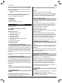
8 Original Instructions
EN
UNO/DUO BOOSTER
Operating Instructions
This high pressure washer has been developed for pro-
fessional use within:
- agriculture, light industry, transport, building and con-
struction, service
Only use the high pressure washer for purposes de-
scribed in this manual.
Regarding the following sections:
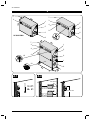
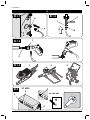
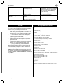
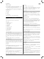
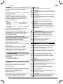
A - Installation
B - Operation
C - Maintenance
please refer to pictures in front of the manual.
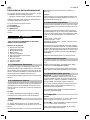
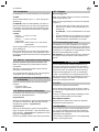
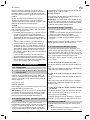
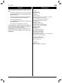
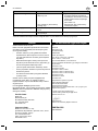
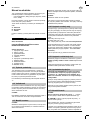
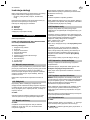
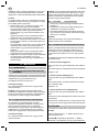
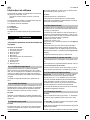
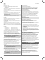
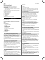
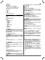
A - Installation
Before starting
DO READ SAFETY INSTRUCTIONS BEFORE USE!
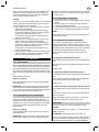
Operating elements:
1. Water connection with fi lter
2. Main switch
3. Starting button
4. Stop button
5. Pressure gauge
6. Connection of high pressure hose
7. Electric cable
8. Service plug
9. Hour counter
10. Oil container
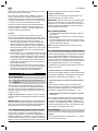
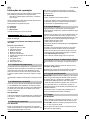
A.1 Temperature conditions
The machine should be installed in a frost-free room. This
applies to pump as well as pipelines incl. of outlet points.
Con cern ing outdoor outlet points it should be possible to
close and emp ty that part of the line which is exposed to
frost.
The maximum ambient temperature for the machine is
40°C.
A.2 Condition of distance
In consideration of the cooling system of the machine and
the accessibility of service, there must be free wall space
on both sides of the machine. To the right 500 mm at a
min i mum and to the left 150 mm at a min i mum.
CS UNO:
The recommended installation height for the machine
is max. 1700 mm measured from the upper edge of the
machine.
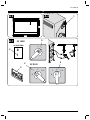
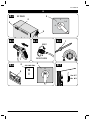
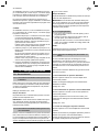
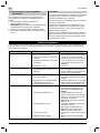
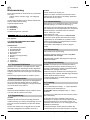
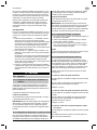
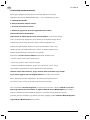
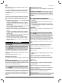
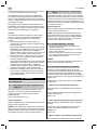
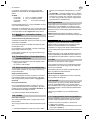
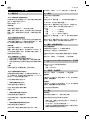
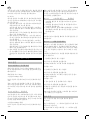
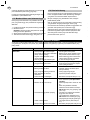
A.3 Wall mounting
CS UNO:
Only mount the machine on a solid wall construction
suited for the mounting of a ma chine. I.e. a concrete or
brick wall.
Do not mount the machine on a wall where it will cause
disturbances in neighbouring rooms (canteens, offi ces
etc.).
CS DUO:
Place the machine on a plane fl oor.
Machine feet have been mounted under the machine.
These must be adjusted so that the machine stands sta-
ble. The feet may be bolted to the fl oor.
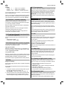
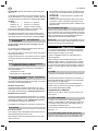
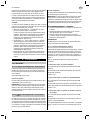
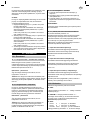
A.4 Water connection
The water connection is made through a fl exible hose
connected to the quick cou pling on the water inlet (1) of
the machine.
The connection can be made to a water supply network
or an internal water sup ply. A shut-off cock should be
mounted on the water supply network in the immediate
vicini ty of the ma chine.
Max. water pressure: 10 bar
Min. water pressure: 1 bar
Max. water inlet temp.: See Technical Specifi cations.
If there is a risk of running sands or other impurities in the
inlet water, a sand fi lter (50 micron) should be mounted
beyond the internal fi lter of the machine (for further con-
nection data see section Tech ni cal Specifi cations).
Clean the water inlet fi lter (1) once a month.
A.5 Mains power connection
Connect the machine to an approved safety switch.
Check voltage, fuse, and cables according to Safety
Instructions.
Connection data conc. power consumption can be taken
from the model tag of the machine.
A.6 High pressure connection
IMPORTANT: When connecting to a pipeline always use
a fl exible hose connection from the outlet of the machine
(pos. 6) - order no. 6300843. Contact your Nilfi sk distribu-
tor for further information.
The outlet of the machine can be connected to a pipeline
with fi xed outlet points, or standard high pres sure hoses
can be connected directly to the outlet of the machine.
It is recommended to let a service tech ni cian authorized
by Nilfi sk prepare the pipeline.
A.7 Venting
CS UNO:
Turn main switch (2) to position - 1 -. Open the outlet
point. Push the green starting button (3).
SC UNO 5M-L: Switch main switch to position - I -. Open
the outlet point.
Let the water run until all air has escaped from the pump
(even water fl ow).
In the case of a recently installed sys tem, or if the pipeline
and the pump have been emptied in any other way, the
system should be vented by starting the pump and then
let the water run at each outlet point of the pipeline at
turns.

9Original Instructions
EN
UNO/DUO BOOSTER
When con nect ing the high pressure hose directly to the
ma chine, the sys tem should be vented by starting the
pump and ac ti vat ing the trigger of the spray handle wit-
hout having attached the spray lance.
CS DUO:
In the case of a recently installed sys tem, or if the pipeline
and the pump have been emptied in any other way, the
system should be vented as follows:
1. At fi rst start pump no. 1 and let the water run from an
outlet point of the pipeline.
When con nect ing the high pressure hose directly to
the ma chine, activate the trigger of the spray handle
without having attached the spray lance.
Let the water run until all air has escaped from the
pump (even water fl ow).
2. Stop pump no. 1. Then start pump no. 2 and let the
water run from an outlet point of the pipeline.
When con nect ing the high pressure hose directly to
the ma chine, activate the trigger of the spray handle
without having attached the spray lance.
Let the water run until all air has escaped from the
pump (even water fl ow).
3. Vent the pipeline by starting one pump and then let the
water run at each outlet point of the pipeline at turns
until all air has escaped from the system.
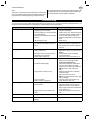
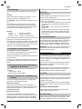
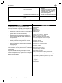
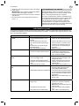
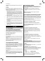
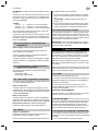
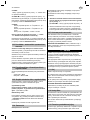
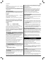
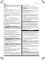
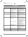
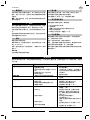
B - Operation
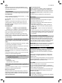
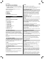
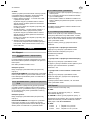
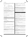
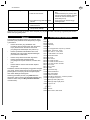
B.1 Connections
B.1.1 High pressure hose - directly on the machine
The Nilfi sk high pressure hose with imprinted max. wor-
king pressure and temperature should be attached to the
outlet connection of the machine (6) by the quick coupling
(a).
Max.extension hose: 50 m.
Danger of scalding!
Never dismount high pressure hoses at water tempera-
tures above 50°C.
IMPORTANT: Prior to dismount-ing of the high pressure
hose the machine should be stopped and the shut-off
cock closed. Then activate the trigger of the spray handle
to relieve the high pres sure hose of pressure.
B.1.2 High pressure hose - to outlet point
In the case of a pipeline with fi xed outlet points the high
pressure hose with imprinted working pressure and
temperature should be attached to the nipple of the high
pres sure cock (1) by the quick coupling (2). Upon attach-
ment turn the handle of the high pressure cock (3) to
open position.
Danger of scalding!
Never dismount high pressure hoses at water tempera-
tures above 50°C.
IMPORTANT: Prior to dismounting of the high pressure
hose or when changing to another outlet point the high
pressure cock should be care ful ly closed. Then activate
the trigger of the spray handle to relieve the high pressure
hose of pressure.
B.1.3 Spray handle - accessories
1. Pull forward the quick coupling trigger (1) of the spray
handle.
2. Insert the nipple of the spray lance (2) in the quick
coupling and release the trigger.
3. Pull forward the spray lance or any other accessory to
ensure correct mounting before starting the machine.
NOTE!
Clean nipple of any impurities each time the spray lance
has been dismounted.
B.1.4 Application of detergents (external)
If you want to apply detergents or disinfectants these
should be dosed to the water through an injector. In con-
junction with the injector it may be ad van ta geous to use a
wall rack on which spray lances, 2 pcs. of 25 l containers
as well as 10 m high pressure hose can be placed.
Below you will fi nd various types of outlet points with
injectors.
1. Outlet point with detachable injector
To be attached to the quick coupling of the high pressure
cock.
To be used for dosing of low-foaming detergents or disin-
fectants.
Dosage 1-8%.
2. Outlet point with detachable foam injector
To be attached to the quick coupling of the high pressure
cock.
To be used in conjunction with foam lance for application
of high-foaming de ter gents or disinfectants.
Dosage 1-5%.
3. Outlet point with cleaning trolley and foam injector
To be attached to the quick coupling of the high pressure
cock.
To be used in the same way as “Outlet point with detach-
able foam injector”.
Makes it possible to place 4 spray lances, 2 pcs. of 25 l
containers as well as 20 m high pressure hose.
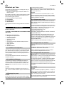
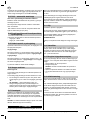
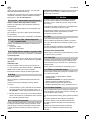
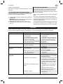
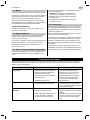
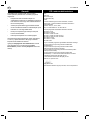
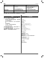
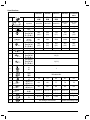
B.2 Start
The shut-off cock on the water inlet should be open.
CS UNO:
Turn the main switch (2) to position - 1 -. Press the green
starting button (3).
SC UNO 5M-L: Switch main switch to position - I -).
Check on the pressure gauge (5) that a pressure is being
built up in the system. If a pressure is not being built up,
vent the machine as de scribed in section A.7 Venting.

10 Original Instructions
EN
UNO/DUO BOOSTER
CS DUO:
Position 1 = Pump no. 1 in operation
Position 2 = Pump no. 2 in operation
Positions 1+2 = Pumps no. 1 and 2 in operation
Turn the main switch (2) to position 1, 2 or 1+2. Push the
green starting button (3).
Check on the pressure gauge (5) that a pressure is being
built up in the system. If a pressure is not being built up,
vent the machine as de scribed in section A.7 Venting.
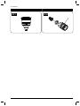
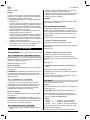
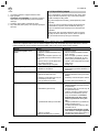
B.3 Operation - automatic start/stop
Always hold the spray lance with both hands!
The machine is automatically activated when the trigger
(1) of the spray handle is activated.
When the trigger is released, the machine automatically
stops after 20 seconds.
When the machine is not in use, the trigger should be
locked with locking device (see arrow).
The spray lance features 2 nozzles, a high pressure
nozzle and a low pressure nozz le.
B.4 FlexoPowerPlus and PowerSpeedVario
- pressure regulation
Turn the outermost part of the FlexoPowerPlus spray
lance:
- High pressure = MAX
- Low pressure = MIN./CHEM.
B.5
Double spray lance, pressure regulation
The spray lance features 2 nozzles - a high pressure
nozzle and a low pressure nozzle.
High pressure mode
When the pressure reducing valve (1) is completely clo-
sed (turned clockwise - B), only the high pressure nozzle
is used - high pressure mode.
Low pressure mode
When the reducing valve (1) is completely opened (turned
counterclockwise - A), both spray lances are used - low
pressure mode / possibility of dosing detergents.
The pres sure may be reg u lat ed between these positions.
B.6 Stop
Danger of scalding!
Never detach high pressure hoses at a water temperature
above 50°C.
Never detach the high pressue hose while the machine is
in operation.
1. To stop the machine, push the red stop button (4) and
turn the main switch (2) to position - 0 -.
SC UNO 5M-L - switch main switch to position - 0 -.
2. Close the shut-off cock of the water inlet and activate
the spray handle or open the high pressure cock to
relieve the pipeline / high pressure hose of pressure.
B.7 Frost protection
The machine should be installed in a frost-free room. This
applies to pump as well as pipelines incl. of outlet points.
Concerning outdoor outlet points it should be possible to
empty that part of the line which is exposed to frost.
IMPORTANT: For safety reasons, hoses, spray lances
and other accessories should always be thawed prior to
use.
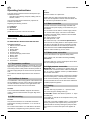
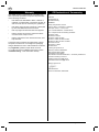
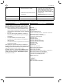
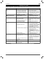
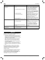
C - Maintenance
It applies to the most exposed components that a mini-
mum of maintenance ensures a prolonged and prob lem-
free operation. Therefore it will be a good idea to make a
habit of the following:
Prior to attaching the water hose and the high pressure
hose, the quick couplings should be cleaned of dust and
sand.
Prior to attaching the spray lance or other accessories to
the spray handle, the machine should be started and the
quick coupling cleaned of dust and sand.
C.1 Oil
Check the oil level in the oil glas.
If the oil level gets too low, the machine will automatically
shut down. The red button will fl ash (does not apply to
SC UNO 5M-L).
In the case of repeated low oil level (oil waste) please
contact a Nilfi sk service technician.
PROTECT THE ENVIRONMENT
Waste oil and oil sludge must be removed as laid down in
the instructions.
C.2 Water fi lter
To avoid debris entering the high pressure pump, a water
fi lter (fi ne) is fi tted at the wa ter inlet. Dependent on the
purity of the water, this fi l ter will have to be cleaned at
regular in ter vals.
The fi lter can be removed when the quick coupling (pos.
1) has been un screwed.
C.3 Cleaning of high pressure nozzle
A clogging up in the nozzle causes a pump pressure
which is too high, and a cleaning is immediately required.
1. Stop the cleaner and detach the spray lance.
2. Clean the nozzle.
IMPORTANT: ONLY use the cleaning tool when the
spray lance is detached.
3. Flush the spray lance backwards with water.
4. If the pressure is still too high, repeat items 1-3.
C.4 Disposable waste
This high pressure washer consists of parts which can
affect the invironment when thrown away. Parts that can
pollute are as follows:
Oil, painted/zinc-coated parts, plastics/plastic-coated

11Original Instructions
EN
UNO/DUO BOOSTER
parts.
Therefore, it is important to follow the laws concerning the
removal of polluting and dangerous materials when repla-
cing spare parts or disposing of high pressure washer.
It is recommended that you bring the rejected parts to wa-
ste disposal areas or recycling plants that are approved
for the destruction of these types of materials.
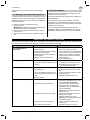
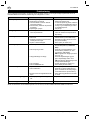
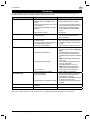
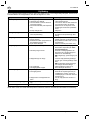
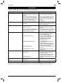
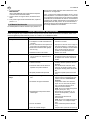
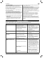
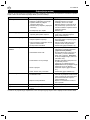
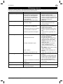
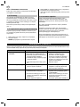
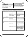
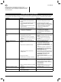
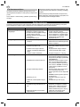
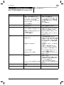
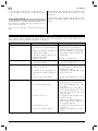
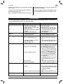
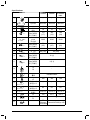
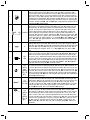
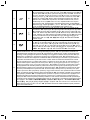
Troubleshooting
You have chosen the best quality and therefore deserve the best service. To avoid unnecessary dis ap point ments, you
should check the following before contacting the nearest Nilfi sk service organisation:
Symptom Reason Action
Machine/pump will not start > A fuse has blown
> Power/plug not connected
> Thermal switches in motor activated
(red lamp fl ashes)
> Thermal relay switched off (red lamp
fl ashes)
> Oil shortage in pump
• Change the fuse.
• Connect power/plug.
• Let the motor cool. Start the machine
and check that the working pressure
is not too high and that the mains
voltage corresponds to the specifi ca-
tions.
• Refi ll with oil.
Fuses blow > Installation does not correspond to
the ampere consumption of the ma-
chine
• Change to an installation correspon-
ding to the ampere consumption of
the machine at a minimum. Replace
the fuse.
Working pressure too low > Nozzle worn
> Wrong spray lance
> Reduction valve of spray lance not
adjusted to max. pressure.
> Nozzle partly clogged up
• Replace the nozzle.
• Replace the spray lance (see section
B4/B5).
• Turn reduction valve completely
counter-clockwise.
• Clean the nozzle (see section C.3).
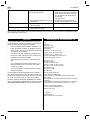
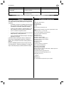
Working pressure not steady > Water temperature too high
> Insuffi cient water supply
> High pressure hoses too long
> Air in the system
> Water inlet fi lter clogged up
• Lower the temperature of the inlet
water to max. temperature (see
Technical Specifi cations).
• Check water inlet fi lter. If that does
not solve the problem, the water
supply for the machine is insuffi cient.
NB! Avoid long, thin hoses (min.
3/4").
• Dismount high pressure extension
hoses and retry.
Extension hose max. 50 m.
NB! Avoid long extension hoses with
many couplings.
• Vent the system (see section A.7).
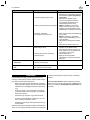
• Clean fi lter (see sect. D.2)
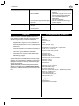
No working pressure > Nozzle clogged up
> No inlet water
> High pressure cock of outlet point
open.
• Clean nozzle (see sect. D.3)
• Check that the shut off cock of the
water inlet is open. Check that the
water supply meets the requirements
(see section A.4)
• Close all high pressure cocks not in
use.
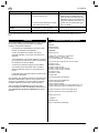
Machine starts and stops > Leaky hose/ pipeline/spray handle • Repair leak.
Machine stops > Oil shortage in pump. Red lamp
fl ashes
• Top up with oil
Should other malfunctions occur than those mentioned above, please contact your nearest Nilfi sk service organisation.

12 Original Instructions
EN
UNO/DUO BOOSTER
Warranty
Your Nilfi sk product is guaranteed for 12 months from
date of purchase (purchase receipt must be presented)
on the following conditions:
• that defects are attributable to fl aws or defects in
materials or workmanship. (Usual wear and tear as
well as misuse are not covered by the guarantee).
• that repairs have not been carried out or attempted
by other than Nilfi sk-trained service staff.
• that only original accessories have been applied.
• that the product has not been exposed to abuse
such as knocks, bumps or frost.
• that the instructions in the manual have been care-
fully observed.
A warranty repair comprises the replacement of defec-
tive parts, but it does not cover freight and packaging
charges. Besides we refer to national Sale of Goods Act.
Any illegitimate guarantee repair will be invoiced.
(I.e. malfunctions due to causes mentioned in section
“Troubleshooting” of the instruction manual).
CE Declaration of Conmormity
We,
Nilfi sk A/S
Banemarksvej 58
DK-2605 Broendby
DENMARK
Hereby solely declare, that the
Products: HPW - Professional - Stationary
Description: 400V, 3~, 50 Hz, IPX5
Type: CS UNO 5M/6P/7P / CS DUO 6P/7P
are in compliance with the following standards:
EN 60335-1:2012
EN 60335-2-79:2012
EN 60204-1:2006+A1:2009
EN 55014-1:2006+A1:2009+A2:2011
EN 55014-2:1997+A1:2001+A2:2008
EN 61000-3-2:2014
EN 61000-3-11:2000
EN 50581:2012
Following the provisions of:
Machinery Directive 2006/42/EC
EMC Directive 2004/108/EC
RoHS Directive 2011/65/EC
Noise Emission Directive 2000/14/EC – Conformity assessment
procedure according to Annex V.
- Measured noise level [dB]: 68-78
- Guaranteed noise level [dB]: 84-93
Hadsund, 2015-01-27
Anton Soerensen
Senior Vice President, Global R&D

13Übersetzung der Originalanleitung
DE
SC UNO/DUO
Betriebsanleitung
Dieser Hochdruckreiniger wurde ent wic kelt für den pro-
fes sio nel len Einsatz in
- Landwirtschaft, Leichte Industrie, Transportgewerbe,
Bau, Service.
Das Gerät nur wie in dieser Be triebs an lei tung beschrie-
ben ver wen den. Ein .
Betr. der folgenden Abschnitte:
A - Installation
B - Bedienung
C - Wartung
vgl. Illustrationen vorne in der Anleitung
.
A - Installation
Vorbereitung
LESEN SIE BITTE VOR DER BENUTZUNG DIE
SICHERHEITSHINWEISE!
Bedienelemente:
1 Wasseranschluß und Wasserfi lter
2 Hauptschalter
3 START-Taste
4 STOP-Taste
5 Manometer
6 Anschluß von Hochdruckschlauch
7 Elektrische Anschlußleitung
8. Servicepfropfen
A.1 Temperaturverhältnisse
Das Gerät muß in einem frostfreien Raum aufgestellt
werden. Dies gilt für sowohl Pumpe als auch Rohr lei tung
und Zapfstellen. Bei Zapfstellen draußen muß es möglich
sein den Teil der Rohrleitung abzusperren und zu entlee-
ren, der frostgefährdet ist.
Die maximale Umgebungstemperatur für das Gerät ist
40°C.
A.2 Abstand
Wegen des Kühlsystems und der Wartungsfreundlichkeit
des Ge rä tes muß es eine Wandfreiheit an beiden Seiten
des Gerätes sein. An der linken Seite mindestens 150
mm und an der rechten Seite min de stens 500 mm.
CS UNO:
Die empfi ehlte Montagehöhe für das Gerät ist max. 170
cm für die obere Kante des Gerätes.
A.3 Wandmontage
CS UNO:
Das Gerät nur an einer tragfähigen und für die Mon ta ge
von einem Gerät geeigneten Wand montieren. Zum Bei-
spiel an einer Wand aus Beton oder Zie gel stein.
Das Gerät nicht an einem Ort installieren, wo es eine
Unannehmlichkeit zu Nebenräumen (Kantine / Büro etc.)
sein kann.
CS DUO:
Das Gerät auf einem ebenen Boden anbringen.
Unter dem Gerät sind Maschinenschuhe montiert. Diese
justieren, damit das Gerät stabil steht. Das Gerät eventu-
ell am Boden befestigen.
A.4 Wasseranschluss
Der Wasseranschluß erfolgt über eine fl exible Schlauch-
verbindung an der Schnellkupplung am Was ser ein laß des
Gerätes (1).
Das Wasser kann aus der öffentlichen Trinkwasserversor-
gung oder einer in ter nen Wasserversorgung ent nom men
werden. Die Montage eines Ab sperr hahns an der Was-
ser ver sor gung in der un mit tel ba ren Nähe des Gerätes ist
erforderlich.
Max. Wasserdruck: 10 bar.
Max. Wasserzulauftemp.: Vgl. Technische Spezifi kati-
onen.
Besteht es eine Gefahr, daß Schwimm sand und andere
Unreinigkeiten im Zu lauf was ser auftreten sollen, muß au-
ßer dem internen Filter des Ge rä tes auch ein Schwimm-
sandfi lter montiert werden.
Übrige Anschlußdaten, vgl. Technische Spezifi katio nen.
Das Wasserzulauffi lter (1) monatlich reinigen.
A.5 Elektrischer Anschluss
Das Gerät nur an eine vorschriftsmäßige elektrische
Installation anschließen.
Überprüfen Sie Spannung, Sicherung und Anschlußlei-
tung gemäß Abschnitt 1 Wichtige Sicherheitsanwei-
sungen.
Anschlußdaten mit Stromverbrauch am Typenschild der
Anlage ablesen.
A.6 Hochdruckanschluss
WICHTIG: Beim Anschluß an eine Rohrleitung muß immer
eine fl exible Schlauchverbindung - Bestellnr. 6300843 - am
Hochdruckanschluß des Gerätes (Pos. 6) montiert werden.
Setzen Sie sich bitte mit Ihrem Nilfi sk-Händler in Verbin-
dung für weitere Informationen.
Den Hochdruckanschluß des Gerätes an eine Rohrleitung
mit fi xen Zapfstellen anschließen, oder serienmäßige
Hochdruck-schläuche direkt an den Hochdruckanschluß
des Gerätes anschließen.
Es empfi ehlt sich eventuelle Rohrleitungen von einem
Nilfi sk geschulten Servicetechniker ausführen zu lassen.
A.7 Venting
CS UNO:
Hauptschalter (2) einschalten, Scahlter in Stellung - 1 -.
Absperrhahn öffnen. Die grüne START-Taste (3) drücken.
SC UNO 5M-L: Den Hauptschalter in Position - I -
drücken. Absperrhahn öffnen.
Das Wasser laufen lassen, bis die Luft aus der Pumpe
ganz entwichen ist (gleichmäßiger Wasserstrom).
Bei neuinstallierten Anlagen, oder wenn die Rohrleitung und

14 Übersetzung der Originalanleitung
DE
SC UNO/DUO
die Pumpe entleert gewesen sind, muß die Anlage da-
durch entlüftet werden, die Pumpe in Betrieb zu setzen und
das Wasser aus jeder Zapfstelle der Rohrleitung abwech-
selnd laufen zu lassen.
Beim Anschluß eines Hochdruckschlauches direkt ans
Gerät, die Anlage dadurch entlüften, die Pumpe in Betrieb
zu setzen und die Spritzpistole zu betätigen, ohne das
Sprührohr zu montieren.
CS DUO:
Bei neuinstallierten Anlagen, oder wenn die Rohrleitung
und die Pumpe an ders entleert gewesen sind, muß die
Anlage gemäß dem untenstehenden Ver fah ren entlüftet
werden:
1. Zuerst Pumpe Nr. 1 starten und das Wasser bei einer
Zapfstelle an der Rohrleitung laufen lassen.
Bei direktem Anschluß des Hochdruckschlauches ans
Gerät die Spritzpistole betätigen, ohne das Sprührohr
zu montieren.
Das Wasser laufen lassen, bis die Luft aus der Pumpe
entwichen ist (gleichmäßiger Wasserstrom).
2. Pumpe Nr.1 stoppen. Danach Pumpe Nr. 2 starten und
das Wasser bei einer Zapfstelle an der Rohrleitung
laufen lassen. Bei direktem Anschluß eines Hoch-
druckschlauches ans Gerät die Spritzpistole betätigen,
ohne das Sprührohr zu montieren.
Das Wasser laufen lassen, bis die Luft aus der Pumpe
ganz entwichen ist (gleichmäßiger Wasserstrom).
3. Die Rohrleitung durch Starten einer Pumpe entlüften
und danach das Wasser abwechselnd bei jeder Zapf-
stelle laufen lassen, bis die Luft aus dem System ganz
entwichen ist.
B - Bedienung
B.1 Anschlüsse
B.1.1 Hochdruckschlauch - direkt am Gerät
Den Nilfi sk Hochdruck schlauch mittels einer Schnell-
kupplung (a) an den Hochdruckanschluß (6) des Gerätes
anschliessen. Max. Arbeitsdruck und Tem pe ra tur sind auf
dem Hochdruckschlauch aufgedruckt.
Max. Verlängerungsschlauch: 50 m.
Verbrühungsgefahr!
Nie den Hochdruckschlauch bei Wassertemperaturen
über 50°C abmontieren.
ACHTUNG! Vor Abmontierung des Ho chdrucks ch lau ches
muß zuerst das Gerät ausgeschaltet und den Absperr-
hahn zu ge dreht werden, wonach die Spritzpistole betätigt
werden muß, um den Hochdruckschlauch zu entlasten.
B.1.2 Hochdruckschlauch - an Zapfstelle
Bei Rohrsystemen mit fi xen Zapfstellen den Hochdruck-
schlauch mittels einer Schnell-kupplung (2) an den Hoch-
druckanschluß (1) des Hochdruck hahns anschliessen.
Nach dem An schluß muß der Griff des Hochdruck hahns
(3) in offene Position gedreht werden.
Verbrühungsgefahr!
Nie den Hochdruckschlauch bei Wassertemperaturen
über 50°C abmontieren.
ACHTUNG! Vor Abmontierung des Hochdruck s chlau ches
oder beim Wech seln der Zapfstelle muß der Hochdruck-
hahn sorgfältig abgedreht und die Spritzpistole betätigt
werden, um den Hochdruckschlauch zu entlasten.
B.1.3 Spritzpistole - Zubehör
1. Den Schnellkupplungsgriff (1) der Spritzpistole nach
vorne ziehen.
2. Den Nip pel (2) des Sprührohrs in die Schnellkupplung
stecken und den Schnell kup plun gsgriff loslassen.
3. Das Sprührohr oder sonstiges Zu be hör nach vorne
zie hen, um korrekte Montage vor der Anwendung des
Hochdruck reini gers zu si chern.
Achtung!
Den Nippel immer von eventuellen Schmutzteilchen säu-
bern, bevor das Sprührohr mit der Spritzpistole verbun-
den wird.
B.1.4 Verwendung von Reinigunsmittelsn (extern)
Das Beimischen von Reinigungs- oder Desinfektions-mit-
teln ist mit dem Reinigungsmittelinjektor möglich. Mit dem
In jek tor kann man mit Vorteil ein Wand ge stell ver wen den,
das die Pla zie rung von Sprührohren, 2 Stück 25 l Be häl-
tern und 10 m Hochdruckschlauch er möglicht.
Unten sind die verschiedenen Typen von Zapfstellen mit
Injektoren abgebildet.
1. Zapfstelle mit abnehmbarem Injektor
An die Schnellkupplung des Hochdruckhahns anschließen.
Zum Gebrauch bei der Auftragung von schwach-schäu-
menden Reinigungs- oder Desinfektionsmitteln.
Dosierung 1-8%.
2. Zapfstelle mit abnehmbarem Injektor
An die Schnellkupplung des Hochdruckhahns anschließen.
Zusammen mit einer Schaum-lanze bei der Auftragung
von hochschäumenden Reinigungs- oder Desinfektions-
mitteln verwenden.
Dosierung 1-5%.
3.
Zapfstelle mit Reinigungs-wagen und Schauminjektor
An die Schnellkupplung des Hochdruckhahns anschliessen.
Wie "Zapfstelle mit abnehmbarem Injektor" zu verwenden.
Ermöglicht die Plazierung von 4 Sprührohren, 2 Stück 25
l Behältern und 20 m Hochdruckschlauch.
B.2 Gerät einschalten
Dafür sorgen, daß der Absperrhahn am Wassereinlaß
offen ist.
CS UNO:
Den Hauptschalter (2) in Position - 1 - drehen. Die grüne
START-Taste (3) drücken.
SC UNO 5M-L: Den Hauptschalter in Position - I -
drücken.

15Übersetzung der Originalanleitung
DE
SC UNO/DUO
Am Ma no me ter (5) kontrollieren, daß ein Druck in der
Anlage entsteht. Wenn nicht, muß das System entlüftet
wer den, vgl. Ab schnitt A.7 Entlüftung.
CS DUO:
Position 1 = Pumpe Nr. 1 im Betrieb
Position 2 = Pumpe Nr. 2 im Betrieb
Position 1+2 = Pumpe Nr. 1 und 2 im Betrieb
Den Hauptschalter (2) in Position 1, 2 oder 1+2 drehen.
Die grüne START-Taste (3) drücken.
Am Ma no me ter (5) kontrollieren, daß ein Druck in der
Anlage entsteht. Wenn nicht, muß das System entlüftet
wer den, vgl. Ab schnitt A.7 Entlüftung.
B.3 Betrieb - Start/Stop-Automatik
Das Sprührohr immer mit beiden Händen halten!
Die Anlage wird bei Betätigung der Spritzpistole (1) auto-
matisch aktiviert.
Wenn den Betätigungshebel der Spritzpistole losgelassen
wird, schaltet die Anlage nach 20 Sekunden automatisch
ab.
Wenn der Reiniger nicht im Betrieb ist, ist die Spritzpistole
durch Betätigung der Sperrklinke (siehe Pfeil) zu schlies-
sen.
B.4 FlexoPowerPlus und PowerSpeedVario -
Druckregulierung
Den äußersten Teil des FlexoPowerPlus Strahlrohrs
drehen:
- Hochdruck = MAX
- Niederdruck = MIN./CHEM.
B.5 Doppelsprührohr, Druckregulierung
Das Sprührohr ist mit zwei Düsen ver se hen, einer Hoch-
druck- und einer Niederdruckdüse.
Hochdruckbetrieb
Wenn der Druckregler (1) völlig geschlossen ist (im Uhr-
zeigersinn - B), wird nur die Hochdruckdüse verwendet
- Hochdruckbetrieb.
Niederdruckbetrieb
Wenn der Druckregler (1) völlig geöffnet ist (gegen den
Uhrzeigersinn - A), werden die beiden Sprührohre
verwendet - Niederdruckbetrieb/Beimischung von Reini-
gungsmitteln.
Der Druck läßt sich zwischen diesen Positionen regulie-
ren.
B.6 Gerät ausschalten
Verbrühungsgefahr!
Nie den Hochdruckschlauch bei Wassertemperaturen
über 50°C abmontieren.
Nie den Hochdruckschlauch abmontieren, wenn die Anla-
ge im Betrieb ist.
1. Die Anlage durch Drehen des Hauptschalters (2) in
Position - 0 - ausschalten.
SC UNO 5M-L: Den Hauptschalter in Position - 0 -
drücken.
2. Den Absperrhahn am Was se rein laß abdrehen und die
Spritzpistole oder den Ho chdruck hahn betätigen um
das Rohrsystem / den Hochdruck s chlau ch zu entla-
sten.
B.7 Frostsicherung
Die Anlage muß in einem frostfreien Raum aufgestellt
werden. Dies gilt für sowohl Pumpe als auch Rohr lei tung
und Zapf stel len. Bei Zapfstellen draußen muß es möglich
sein den Teil der Rohrleitung ab zusper ren und zu entlee-
ren, der frost ge fähr det ist.
ACHTUNG: Vor Verwendung der Schläuche, des Sprüh-
rohrs und anderer Zubehörteile, müssen diese aus
Sicherheits-gründen eisfrei sein.
C - Wartung
Für die Komponenten, die am meisten beansprucht sind,
gilt jedoch, daß ein Minimum an Wartung einen lang-
wierigen und problemfreien Betrieb sichern kann. Es ist
daher eine gute Idee das Folgende zur Gewohn heit zu
machen:
Bevor der Wasserzulauf-schlauch und der Hochdruck-
schlauch montiert werden, sind Schnellkupplungen von
Staub und Sand sauber zu spülen.
Bevor Sprührohr oder sonstiges Zubehör montiert wird, ist
das Gerät und die Schnellkupplung von Sand und Staub
sauber zu spülen.
C.1 Öl
Den Ölstand im Ölglas überprüfen.
Wird der Ölstand zu niedrig, schaltet die Anlage automa-
tisch aus.
Bei wiederholtem niedrigen Ölstand (Ölschwindung)
einen Nilfi sk Servicetechniker anrufen.
DIE NATUR SCHÜTZEN
Altöl muß in vorschriftsmäßiger Weise entsorgt werden.
C.2 Wasserfi lter
Am Wassereinlaß ist ein Wasserfi lter (fein) montiert,
das das Eindringen von Schmutzpartikeln in die Pumpe
ver hin dern soll. Abhängig von der Reinheit des Wassers
ist dieses Filter gelegentlich zu reinigen. Das Filter läßt
sich herausnehmen, wenn die Schnellkupplung (Pos. 1)
abgeschraubt worden ist.
C.3 Reinigung der Hochdruckdüse
Eine Verstopfung der Düse verursacht einen zu hohen
Pumpendruck. Die Reinigung ist deshalb sofort erforder-
lich.
1.
Das Gerät ausschalten und das Sprührohr abmontieren.
2. Düse reinigen.
VORSICHT: Reinigungsnadel nur anwenden, wenn
das Sprührohr demontiert ist!
3. Sprührohr mit Wasser von der Düsenseite her durch-
spülen.
4. Falls der Druck noch zu hoch ist, Punkt 1 bis 3 wieder-
holen.

16 Übersetzung der Originalanleitung
DE
SC UNO/DUO
C.4 Zerlegung/Entsorgung
Dieser Hochdruckreiniger besteht aus Teilen, die bei der
Entsorgung der Umwelt schaden können. Z.B. können
folgende Teile die Umwelt verschmutzen:
Öl, gestrichene / verzinkte Teile, Kunststoff / kunststoff-
geschützte Teile. Es ist deshalb wichtig, daß man bei
Auswechselung von Ersatzteilen oder Wegwerfen des
Reinigers die Gesetze der einzelnen Länder wegen
Entfernung von Materialien, die gefährlich sind und die
Umwelt verschmutzen, folgt. Es wird empfohlen, daß man
die ausrangierten Teile an Abfall-plätze oder Recyclings-
anlagen bringt.
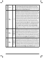
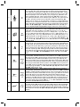
Behebung von Störungen
Sie haben die beste Qualität gewählt und verdienen daher den besten Service. Um unnötigen Ärger zu ver mei den,
sollten Sie Folgendes überprüfen, bevor Sie sich an die Nilfi sk-Serviceorganisation wenden:
Störung Ursache Behebung
Gerät startet nicht > Sicherung durchgebrannt
> Strom nicht angeschlossen
> Thermoschalter im Motor
aktiviert
> Thermorelais ausgelöst (rote START-
Taste leuchtet)
> Ölmangel in der Pumpe
• Sicherung auswechseln.
• Strom/Stecker anschliessen.
• Motor kühlen lassen. Anlage in
Betrieb setzen und danach prüfen,
daß der Arbeitsdruck nicht zu hoch
ist, und daß die Netzspannung den
Spezifi kationen entspricht.
• Öl auffüllen.
Sichrungen brennen durch > Installation entspricht nicht dem Am-
perenverbrauch der Anlage
• Auf Installation wechseln, die min-
destens dem Amperenverbrauch
der Anlage entspricht. Sicherung
auswechseln.
Arbeitsdruck zu niedrig > Düse abgenutzt
> Falsches Sprührohr
> Reduktionsventil am Sprührohr nicht
auf max. Druck eingestellt
> Düse teilweise verstopft
• Düse auswechseln.
• Sprührohr auswechseln (vgl Ab-
schnitt B.4/B.5).
• Reduktionsventil entgegen Uhrzei-
gersinn bis auf Anschlag drehen (vg.
Abschnitte B.5.
• Düse reinigen (vgl. Abschnitt C.3).
Arbeitsdruck schwankt > Wassertemperatur zu hoch
> Wasserversorgung ungenügend
> Hochdruckschläuche zu lang
> Luft in der Anlage
> Wasserzulauffi lter verstopft
• Die Temperatur des Zulaufwassers
bis auf max. Temperatur senken (vgl.
Technische Spezifi kationen).
•
Wasserzulauffi lter kontrollieren. Löst
dies nicht das Problem, ist die Wasser-
versorgung zur Anlage ungenügend.
NB! lange, dünne Schläuche vermei-
den (min 3/4").
• Hochdruckverlängerungsschläuche
abmontieren und wieder versuchen.
Verlängerungsschlauch max. 50 m.
• NB! Lange Verlängungsnschläuche
mit zu vielen Kupplungen vermeiden.
• Anlage entlüften (vgl. Abschnitt A.7).
• Filter reinigen (vgl. Abschnitt D.2)
Kein Arbeitsdruck > Düse verstopft
> Kein Zulaufwasser
> Hochdruckhahn an der Zapfstelle ist
offen
• Düse reinigen (vgl. Abschnitt D.3)
• Überprüfen, ob der Absperrhahn am
Wassereinlaß offen ist. Kontrollieren,
ob die Wasserversorgung den
Forderungen erfüllt (vgl. Abschn. A.4)
• Alle nicht verwendeten Hochdruck-
hähne abdrehen.
Anlage schaltet ein und aus > Undichtigkeit an Schlauch/Rohr-
leitung/Spritzpistole
• Undichtigkeit ausbessern.
Anlage schaltet aus > Ölmangel in der Pumpe. Rote Lichte
blinkt
• Öl auffüllen
Sollten andere als die hier erwähnten Betriebsstörungen auftreten, setzen Sie sich bitte mit Ihrer nächsten Nilfi sk-
Ser vice händ ler in Verbindung.

17Übersetzung der Originalanleitung
DE
SC UNO/DUO
Garantie
Nilfi sk leistet eine einjährige Garantie auf diese Anlage.
Die Garantiezeit beginnt mit dem Datum des Kaufbe-
legs. Wird das Gerät oder das Zubehör zur Reparatur
ein gereicht, muß eine Kopie des Kaufbelegs beigefügt
werden.
• daß Mängel auf Material- oder Herstellungsfehler
zurück-zuführen sind.
(Normaler Verschleiß und fehlerhafte Bedienung
können dieser Voraussetzung nicht zugesch rieben
werden).
• daß Reparatur nur von Nilfi sk-geschultem Service-
personal ausgeführt worden ist.
• daß nur Original-Nilfi sk-Zubehörteile verwendet
wurden.
• daß die Anlage nicht durch äußere Einwirkung be-
schädigt wurde (z.B. durch Stoß, Sturz oder Frost).
• die Anweisungen in der Be triebs an leitung genau
beachtet wurden.
Die Garantiereparatur umfaßt das Auswechseln defekter
Teile (ausschließlich Verpackung und Versand). Ausser-
dem verweisen wir auf nationale gesetzliche Regelungen.
Jede nicht berechtigte Garantiereparatur wird in Rech-
nung gestellt werden. (Zum Beispiel Betriebs-störungen
aus Ursachen, die im Abschnitt Behebung von Stö-
rungen der Betriebsanleitung erwähnt sind).
CE Konformitätserklärung
Wir,
Nilfi sk A/S
Banemarksvej 58
DK-2605 Broendby
DÄNEMARK
erklären hiermit, dass die Produkte:
Produkte: HPW - Professionell - Stationär
Beschreibung: 400V, 3~, 50 Hz, IPX5
Typ: CS UNO 4M/5M/6P/7P / CS DUO 6P/7P
den folgenden Normen entsprechen:
EN 60335-1:2012
EN 60335-2-79:2012
EN 60204-1:2006+A1:2009
EN 55014-1:2006+A1:2009+A2:2011
EN 55014-2:1997+A1:2001+A2:2008
EN 61000-3-2:2014
EN 61000-3-11:2000
EN 50581:2012
Entsprechend den Vorschriften von:
Maschinenrichtlinie 2006/42/EG
EMV-Richtlinie 2004/108/EG
RoHS-Richtlinie 2011/65/EG
Outdoorrichtlinie 2000/14/EG – Konformitätsbewertungsverfah-
ren nach Anlage V.
- Gemessener Schallleistungspegel [dB]: 68-78
- Garantierter Schallleistungspegel [dB]: 84-93
Hadsund, 2015-01-27
Anton Soerensen
Senior Vice President, Global R&D

18 Traduction du manuel d’origine
FR
SC UNO/DUO
Instructions de fonctionnement
Ce nettoyeur à haute pression est conçu pour un usage
professionnel dans les domaines suivants :
- agriculture, industrie légère, transports, BTP, services
Utilisez le nettoyeur haute pression exclusivement pour
les usages décrits dans ce manuel.
En ce qui concerne les points suivants :
A - Installation
B - Fonctionnement
C - Maintenance
référez-vous aux illustrations qui se trouvent au début du
manuel.
A - Installation
Avant la mise en marche
VEUILLEZ LIRE LES CONSIGNES DE SÉCURITÉ
AVANT TOUTE UTILISATION !
Éléments de commande
1. Arrivée d’eau avec fi ltre
2. Interrupteur principal
3. Bouton de démarrage
4. Bouton d’arrêt
5. Indicateur de pression
6. Raccord du fl exible haute pression
7. Câble électrique
8. Bouchon d'entretien
9. Compteur horaire
10. Réservoir d'huile
A.1 Conditions de température
La machine, la pompe, les canalisations et les points
d’écoulement doivent être installés dans un endroit hors
gel. Si certains points d’écoulement sont en plein air (ex-
térieur), il serait bon d’installer un robinet afi n de pouvoir
purger la partie de l’installation exposée au gel.
La température ambiante maximum pour la machine est
de 40°C.
A.2 Conditions de distance
IIl faut impérativement maintenir une certaine distance de
chaque côté de la machine, compte tenu du système de
refroidissement et de l’accessibilité au service. À savoir
500 mm minimum du côté droit, et 150 mm minimum du
côté gauche.
CS UNO:
La hauteur d’installation recommandée pour la partie
supérieure de la machine est de 1700 mm maximum.
A.3 Pose murale
CS UNO:
La machine doit être fi xée sur un mur solide, spéciale-
ment adapté, par exemple un mur en béton ou un mur en
brique.
Ne jamais fi xer la machine sur un mur pouvant créer des
perturbations dans les pièces voisines (cantines, bu-
reaux, etc.).
CS DUO:
Posez la machine sur un sol plat. Réglez la hauteur des
pieds pour garantir la stabilité parfaite de la machine. Le
pied peut être boulonné au sol.
A.4 Branchement hydraulique
Le branchement hydraulique se fait au moyen d’un tuyau
fl exible monté sur le raccord rapide d’arrivée d’eau (1) de
la machine.
Le branchement peut être réalisé à partir du réseau pu-
blic d’alimentation en eau ou d’une source d’alimentation
interne. Un robinet de fermeture doit impérativement être
monté sur le circuit d’alimentation, à proximité du net-
toyeur.
Pression d’eau: 10 bars maxi.
Pression d'eau min. : 1 bar
Température d’arrivée d’eau : reportez-vous à la section
Données techniques.
Si l’eau d’arrivée est susceptible de contenir du sable en
suspen-sion ou toute autre impureté, vous devez installer
un fi ltre à sable (50 microns) en plus du fi ltre interne de la
machine (pour davantage d’informations sur les données
de raccordement, reportez-vous à la section Données
techniques).
Nettoyez le fi ltre d’arrivée d’eau (1) une fois par mois.
A.5 Branchement électrique
Connecter la machine à un interrupteur de sécurité homo-
logué.
Vérifi ez la tension électrique, les fusibles et les câbles
conformé-ment à Consignes de sécurité.
Les informations de branche-ment relative à la consom-
mation fi gurent sur la plaque signalétique de la machine.
A.6 Branchement haute pression
IMPORTANT : si vous raccordez la machine à un
système de canalisation, réalisez toujours une connexi-
on à tuyau fl exible au niveau du raccord de sortie de la
machine (pos. 6) - référence : 6300843. Contactez votre
revendeur Nilfi sk pour de plus amples informations.
Le raccord de sortie de la machine peut être relié à une
canalisation (avec points d’écoulement fi xes) ou à un
fl exible haute pression standard.
Il est conseillé de faire installer la canalisation par des
techniciens spécialisés Nilfi sk.
A.7 Purge d'air
CS UNO:
Mettre le bouton sur la position -1-. Ouvrir le point d’écou-
lement. Appuyer sur le bouton marche vert (3).
SC UNO 5M-L : mettre l'interrupteur principal sur la posi-
tion - I -. Ouvrir le point d’écoulement.
couler l’eau jusqu’à la purge complète de l’air contenu
dans la pompe (débit d’eau régulier).

19Traduction du manuel d’origine
FR
SC UNO/DUO
Si l’installation est neuve, ou si la canalisation et la pom-
pe ont été vidées par un autre moyen, vous devez purger
le système en démarrant la pompe et en laissant couler
l’eau à chaque point d’écoulement de la canalisation.
En cas de raccordement direct de la machine sur un
fl exible haute pression, purgez l’installation en démarrant
la pompe puis en activant la gâchette de la poignée sans
avoir monté la lance.
CS DUO:
Si l’installation est neuve, ou si la canalisation et la pom-
pe ont été vidées par un autre moyen, vous devez purger
le système comme suit :
1. Démarrez la pompe n°1 et laissez couler l’eau depuis
un point d’écoulement de la canalisation.
En cas de raccordement direct de la machine sur un
fl exible haute pression, activez la gâchette de la poi-
gnée sans avoir monté la lance.
Laissez couler l’eau jusqu’à la purge complète de l’air
contenu dans la pompe (débit d’eau régulier).
2. Arrêtez la pompe n°1 puis démarrez la pompe n°2 et
laissez couler l’eau depuis un point d’écoulement de la
canalisation.
En cas de raccordement direct de la machine sur un
fl exible haute pression, activez la gâchette de la poi-
gnée sans avoir monté la lance.
Laissez couler l’eau jusqu’à la purge complète de l’air
contenu dans la pompe (débit d’eau régulier).
3. Purgez la canalisation en démarrant une pompe puis
en laissant couler l’eau à chaque point d’écoulement
de la canalisation, jusqu’à la purge complète de l’air
contenu dans l’installation.
B - Consignes d'utilisation
B.1 Raccordements
B.1.1 Raccordement du fl exible haute pression sur
la machine
Reliez entre eux le raccord de sortie (6) de la machine et
le rac cord rapide (a) du fl exible à haute pression Nilfi sk,
sur lequel sont imprimées la température et la pression
de service maximales.
Rallonge de fl exible maxi. : 50 m
Risque de brûlure !
Ne jamais démonter un fl exible haute pression si la tem-
pérature de l’eau dépasse 50°C.
IMPORTANT : avant de dé mon ter le fl exible haute pres-
sion, stop pez la machine et fermez le robinet d’arrêt.
Activez ensuite la poignée-gâchette pour dé com pres ser
le fl exible haute pres sion.
B.1.2 Raccordement du fl exible haute pression sur
une canalisation
Dans le cas d’une canalisation avec points d’écoulement
fi xes, reliez entre eux le manchon fi leté du robinet (1) et
le raccord rapide (2) du fl exible haute pression Nilfi sk, sur
lequel sont imprimées la température et la pression de
service maximales. Tournez ensuite la poignée du robinet
(3) pour ouvrir la vanne.
Risque de brûlure !
Ne jamais démonter un fl exible haute pression si la tempé-
rature de l’eau dépasse 50°C.
IMPORTANT: avant de démonter le fl exible haute pres-
sion, ou de le déplacer vers un autre point d’écoulement,
fermez soigneuse-ment le robinet à haute pression (3).
Activez ensuite la poignée-gâchette pour décompresser
le fl exible haute pression.
B.1.3 Poignée-gâchette
1. Tirez vers l’avant l’embout à raccord rapide (1) de la
poignée-gâchette.
2. Insérez le manchon cannelé (2) de la lance dans le
raccord rapide, puis relâchez l’embout.
3. Essayez de tirer sur la lance, ou tout autre accessoire
inséré, pour vérifi er la solidité du montage avant l’utili-
sation du nettoyeur.
NOTE !
Débarrassez le manchon cannelé de toute impureté
après chaque démontage de la lance.
B.1.4 Application de détergents (alimentation ex-
terne)
Si vous souhaitez appliquer des détergents ou des
désinfectants, vous devez les doser au moyen d’un
injecteur externe. Outre l’injecteur, il peut être intéressant
d’acquérir un support mural sur lequel placer les lances,
deux bidons de 25 L et un fl exible haute pression de 10
mètres.
Vous trouvez ci-dessous différents de types de raccorde-
ment avec injecteur.
1. Raccordement d’un injecteur détachable
Montez l’injecteur externe sur le raccord rapide de la
vanne haute pression.
Destiné au dosage de détergents et de désinfectants
faiblement moussant.
Dosage de 1 à 8%.
2. Raccordement d’un injecteur à mousse détachable
Montez l’injecteur à mousse sur le raccord rapide de la
vanne haute pression.
À utiliser conjointement avec la lance à mousse, pour
l’application de détergents et de désinfectants fortement
moussant.
Dosage de 1 à 5%.
3. Chariot de nettoyage et injecteur à mousse
Montez l’injecteur sur le raccord rapide de la vanne haute
pression.
Utilisez comme décrit au paragraphe précédent («Raccor-
dement d’un injecteur à mousse détachable“).
Chariot de nettoyage pour 4 lances, 2 bidons de 25 litres
et 1 fl exible haute pression de 20 mètres.

20 Traduction du manuel d’origine
FR
SC UNO/DUO
B.2 Démarrage
Le robinet d’arrêt de l’ali-mentation en eau doit être ou-
vert.
CS UNO :
Mettez l’interrupteur principal (2) en position - 1 -. Ap-
puyez sur le bouton de démarrage vert (3).
SC UNO 5M-L : mettre l'interrupteur principal sur la posi-
tion - I -.
Sur l’indicateur de pression (5), assurez-vous que la
pression augmente progressivement dans la machine.
Si tel n’est pas le cas, purgez la machine comme décrit
précédemment (voir la section «Purge d’air»).
CS DUO :
Position 1 = Pompe n°1 en action
Position 2 = Pompe n°2 en action
Positions 1+2 = Pompes n°1 et 2 en action
Mettez l’interrupteur principal (2) en position 1, 2 ou 1+2.
Appuyez sur le bouton de démarrage vert (3).
Sur l’indicateur de pression (5), assurez-vous que la pres-
sion aug men te progressivement dans la machine. Si tel
n’est pas le cas, purgez la machine comme décrit précé-
demment (voir la sec tion A.7 Purge d’air).
B.3 Système de marche-arrêt automatique
Tenez toujours la lance à deux mains !
La machine se met automatiquement en route lorsque
vous pressez la gâchette de la poignée (1).
Quand vous la relâchez, la machine s’arrête d’elle-même
rès 20 secondes.
Lorsque vous n’utilisez pas la machine, pensez à verrouil-
ler la gâchette en bloquant le dispositif de sécurité (voir
fl èche).
B.4 FlexoPowerPlus et PowerSpeedVario -
régulation de la pression
Tourner l'extrémité de la lance de pulvérisation Flexo-
PowerPlus :
- Haute pression = MAX
- Basse pression = MIN./CHEM.
B.5 Lance à double voie - régulation de la
pressure
La lance est équipée de deux buses, une buse haute
pression et une buse basse pression.
Mode haute pression
Lorsque la vanne de détente (1) est complètement
fermée (tournée dans le sens horaire - B), seule la buse
haute pression est utilisée. La machine fonctionne en
mode haute pression.
Mode basse pression
Lorsque la vanne de détente (1) est complètement
ouverte (tournée dans le sens anti-horaire - A), les deux
buses sont utilisées. La machine fonctionne en mode
basse pression / possibilité de dosage des détergents.
La pression peut être réglée entre ces deux positions.
B.6 Arrêt
Risque de brûlure !
Ne jamais démonter un fl exible haute pression si la tem-
pérature de l’eau dépasse 50°C.
Ne jamais démonter le fl exible haute pression si la machi-
ne est en cours d’utilisation.
1. Pour arrêter la machine, appuyer sur le bouton d'arrêt
rouge (4) et tourner l'interrupteur principal (2) sur la
position - 0 -.
SC UNO 5M-L - tourner l'interrupteur principal sur la
position - 0 -.
2. Fermez le robinet d’arrivée d’eau, puis activez la poi-
gnée-gâchette ou bien ouvrez le robinet haute pres-
sion pour décompresser la canalisation et le fl exible
haute pression.
B.7 Dispositif antigel
La machine, la pompe, les cana-lisations et les points
d’écoule-ment doivent être installés dans un endroit hors
gel. Si certains points d’écoulement sont en plein air
(extérieur), il est imperatif d’installer un robinet afi n de
pouvoir purger la partie de l’installation exposée au gel.
IMPORTANT : par mesure de sécurité, assurez-vous que
les fl exibles, les lances et les autres accessoires sont
dégelés avant de les utiliser.
C - Entretien
Les composants les plus exposés ont besoin d’un mini-
mum d’entretien pour garantir un fonctionnement durable
et sans problème. Dans l’intérêt de votre équipement, il
est donc conseillé que vous appliquiez régulièrement les
conseils suivants :
Avant de monter le fl exible d’arrivée d’eau et le fl exible
haute pression, nettoyez les raccords rapides afi n de
retirer sable et poussière.
Avant de monter la lance ou tout autre accessoire sur la
poignée-gâchette, démarrez la machine et nettoyez le
raccord rapide afi n de retirer sable et poussière.
C.1 Huile
Vérifi ez le niveau d’huile dans le verre de regard d’huile.
Si le niveau d’huile tombe trop bas, la machine s’arrêtera
automatiquement. Le bouton rouge clignote (sauf sur le
modèle SC UNO 5M-L).
Si jamais le niveau d’huile diminue de manière répétée
(déchet d’huile), veuillez contacter un technicien de SAV
de Nilfi sk.
PROTÉGEZ L’ENVIRONNEMENT
L’huile usagée et le cambouis doivent être récupérés
selon la réglementation en vigueur.
C.2 Filtre à eau
L’arrivée d’eau est équipée d’un fi ltre empêchant les im-
puretés d’entrer dans la pompe à haute pression. Netto-
yez ce fi ltre régulièrement, selon la pureté de l’eau.
Pagina se încarcă...
Pagina se încarcă...
Pagina se încarcă...
Pagina se încarcă...
Pagina se încarcă...
Pagina se încarcă...
Pagina se încarcă...
Pagina se încarcă...
Pagina se încarcă...
Pagina se încarcă...
Pagina se încarcă...
Pagina se încarcă...
Pagina se încarcă...
Pagina se încarcă...
Pagina se încarcă...
Pagina se încarcă...
Pagina se încarcă...
Pagina se încarcă...
Pagina se încarcă...
Pagina se încarcă...
Pagina se încarcă...
Pagina se încarcă...
Pagina se încarcă...
Pagina se încarcă...
Pagina se încarcă...
Pagina se încarcă...
Pagina se încarcă...
Pagina se încarcă...
Pagina se încarcă...
Pagina se încarcă...
Pagina se încarcă...
Pagina se încarcă...
Pagina se încarcă...
Pagina se încarcă...
Pagina se încarcă...
Pagina se încarcă...
Pagina se încarcă...
Pagina se încarcă...
Pagina se încarcă...
Pagina se încarcă...
Pagina se încarcă...
Pagina se încarcă...
Pagina se încarcă...
Pagina se încarcă...
Pagina se încarcă...
Pagina se încarcă...
Pagina se încarcă...
Pagina se încarcă...
Pagina se încarcă...
Pagina se încarcă...
Pagina se încarcă...
Pagina se încarcă...
Pagina se încarcă...
Pagina se încarcă...
Pagina se încarcă...
Pagina se încarcă...
Pagina se încarcă...
Pagina se încarcă...
Pagina se încarcă...
Pagina se încarcă...
Pagina se încarcă...
Pagina se încarcă...
Pagina se încarcă...
Pagina se încarcă...
Pagina se încarcă...
Pagina se încarcă...
Pagina se încarcă...
Pagina se încarcă...
Pagina se încarcă...
Pagina se încarcă...
Pagina se încarcă...
Pagina se încarcă...
Pagina se încarcă...
Pagina se încarcă...
Pagina se încarcă...
Pagina se încarcă...
Pagina se încarcă...
Pagina se încarcă...
Pagina se încarcă...
Pagina se încarcă...
Pagina se încarcă...
Pagina se încarcă...
Pagina se încarcă...
Pagina se încarcă...
Pagina se încarcă...
Pagina se încarcă...
Pagina se încarcă...
Pagina se încarcă...
Pagina se încarcă...
Pagina se încarcă...
Pagina se încarcă...
Pagina se încarcă...
Pagina se încarcă...
Pagina se încarcă...
Pagina se încarcă...
Pagina se încarcă...
Pagina se încarcă...
Pagina se încarcă...
Pagina se încarcă...
Pagina se încarcă...
Pagina se încarcă...
Pagina se încarcă...
Pagina se încarcă...
Pagina se încarcă...
Pagina se încarcă...
Pagina se încarcă...
Pagina se încarcă...
Pagina se încarcă...
Pagina se încarcă...
Pagina se încarcă...
Pagina se încarcă...
Pagina se încarcă...
Pagina se încarcă...
Pagina se încarcă...
Pagina se încarcă...
Pagina se încarcă...
Pagina se încarcă...
Pagina se încarcă...
Pagina se încarcă...
Pagina se încarcă...
Pagina se încarcă...
Pagina se încarcă...
Pagina se încarcă...
Pagina se încarcă...
Pagina se încarcă...
Pagina se încarcă...
Pagina se încarcă...
Pagina se încarcă...
Pagina se încarcă...
Pagina se încarcă...
Pagina se încarcă...
Pagina se încarcă...
Pagina se încarcă...
Pagina se încarcă...
Pagina se încarcă...
Pagina se încarcă...
Pagina se încarcă...
Pagina se încarcă...
Pagina se încarcă...
Pagina se încarcă...
Pagina se încarcă...
Pagina se încarcă...
Pagina se încarcă...
Pagina se încarcă...
Pagina se încarcă...
Pagina se încarcă...
Pagina se încarcă...
Pagina se încarcă...
-
 1
1
-
 2
2
-
 3
3
-
 4
4
-
 5
5
-
 6
6
-
 7
7
-
 8
8
-
 9
9
-
 10
10
-
 11
11
-
 12
12
-
 13
13
-
 14
14
-
 15
15
-
 16
16
-
 17
17
-
 18
18
-
 19
19
-
 20
20
-
 21
21
-
 22
22
-
 23
23
-
 24
24
-
 25
25
-
 26
26
-
 27
27
-
 28
28
-
 29
29
-
 30
30
-
 31
31
-
 32
32
-
 33
33
-
 34
34
-
 35
35
-
 36
36
-
 37
37
-
 38
38
-
 39
39
-
 40
40
-
 41
41
-
 42
42
-
 43
43
-
 44
44
-
 45
45
-
 46
46
-
 47
47
-
 48
48
-
 49
49
-
 50
50
-
 51
51
-
 52
52
-
 53
53
-
 54
54
-
 55
55
-
 56
56
-
 57
57
-
 58
58
-
 59
59
-
 60
60
-
 61
61
-
 62
62
-
 63
63
-
 64
64
-
 65
65
-
 66
66
-
 67
67
-
 68
68
-
 69
69
-
 70
70
-
 71
71
-
 72
72
-
 73
73
-
 74
74
-
 75
75
-
 76
76
-
 77
77
-
 78
78
-
 79
79
-
 80
80
-
 81
81
-
 82
82
-
 83
83
-
 84
84
-
 85
85
-
 86
86
-
 87
87
-
 88
88
-
 89
89
-
 90
90
-
 91
91
-
 92
92
-
 93
93
-
 94
94
-
 95
95
-
 96
96
-
 97
97
-
 98
98
-
 99
99
-
 100
100
-
 101
101
-
 102
102
-
 103
103
-
 104
104
-
 105
105
-
 106
106
-
 107
107
-
 108
108
-
 109
109
-
 110
110
-
 111
111
-
 112
112
-
 113
113
-
 114
114
-
 115
115
-
 116
116
-
 117
117
-
 118
118
-
 119
119
-
 120
120
-
 121
121
-
 122
122
-
 123
123
-
 124
124
-
 125
125
-
 126
126
-
 127
127
-
 128
128
-
 129
129
-
 130
130
-
 131
131
-
 132
132
-
 133
133
-
 134
134
-
 135
135
-
 136
136
-
 137
137
-
 138
138
-
 139
139
-
 140
140
-
 141
141
-
 142
142
-
 143
143
-
 144
144
-
 145
145
-
 146
146
-
 147
147
-
 148
148
-
 149
149
-
 150
150
-
 151
151
-
 152
152
-
 153
153
-
 154
154
-
 155
155
-
 156
156
-
 157
157
-
 158
158
-
 159
159
-
 160
160
-
 161
161
-
 162
162
-
 163
163
-
 164
164
-
 165
165
-
 166
166
-
 167
167
-
 168
168


Nilfisk-ALTO SC DUO Operating Instructions Manual
- Tip
- Operating Instructions Manual
- Acest manual este potrivit și pentru
în alte limbi
- slovenčina: Nilfisk-ALTO SC DUO
Lucrări înrudite
Alte documente
-
Nilfisk C 135.1-8 PAD Manualul proprietarului
-
-
-
-
Dolmar HP351 Manualul proprietarului
-
Ferm GRM1015 Manual de utilizare
-
-
Ferm GRM1012 Manualul proprietarului
-
-
Comet K 250 Manual de utilizare