
59G678
STRUG ELEKTRYCZNY
ELECTRIC PLANER
ELEKTROHOBEL
РУБАНОК ЭЛЕКТРИЧЕСКИЙ
ГЕМБЕЛЬ ЕЛЕКТРИЧНИЙ
ELEKTROMOS KÉZIGYALU
RINDEA ELECTRICA
ELEKTRICKÝ HOBLÍK
ELEKTRICKÝ HOBLÍK
ELEKTRIČNI OBLIČ
ELEKTRINIS OBLIUS
ELEKTRISKĀ ĒVELE
ELEKTRILINE HÖÖVEL
ЕЛЕКТРИЧЕСКО РЕНДЕ
ELEKTRIČNA BLANJALICA
ELEKTRIČNA BLANJA
ΗΛΕΚΤΡΙΚΗ ΠΛΑΝΗ
PIALLETTO ELETTRICO
ES
CEPILLO ELÉCTRICO
FR RABOT ÉLECTRIQUE
G.0419
* Części zamienne do tego produktu kupisz w gtxservice.pl przez min. 10 lat od jego zakupu.
Sklep gtxservice.pl realizuje min. 95% zamówień w skali roku.

2

3
INSTRUKCJA OBSŁUGI ..................... 6
INSTRUCTION MANUAL ................... 13
BETRIEBSANLEITUNG ..................... 18
РУКОВОДСТВО ПО ЭКСПЛУАТАЦИИ ...... 23
ІНСТРУКЦІЯ З ЕКСПЛУАТАЦІЇ. . . . . . . . . . . . . . 28
HASZNÁLATI UTASÍTÁS .................... 33
INSTRUCTIUNI DE DESERVIRE ............. 38
INSTRUKCE K OBSLUZE .................... 43
NÁVOD NA OBSLUHU ..................... 48
NAVODILA ZA UPORABO .................. 53
APTARNAVIMO INSTRUKCIJA .............. 58
LIETOŠANAS INSTRUKCIJA ................ 63
KASUTUSJUHEND ......................... 68
ИНСТРУКЦИЯ ЗА ОБСЛУЖВАНЕ .......... 73
UPUTE ZA UPOTREBU ..................... 78
UPUTSTVO ZA UPOTREBU ................. 83
ΟΔΗΓΙΕΣ ΧΡΗΣΗΣ ......................... 88
MANUALE PER L’USO ...................... 93
MANUAL DE USUARIO ..................... 98
MANUEL D’INSTRUCTION ................. 103
ES
FR

4
23
4
1
20
8
11
9
10
14
7
6
12
13
5
19

5
A
5
19
B
20
5
19
C
5
19
D
10
98
11
E
13
12
F
7
6
1
3
2
G
press
H
max
3mm
I
6
18
JK
21
17
16
15
L
22

6
INSTRUKCJA ORYGINALNA (OBSŁUGI)
STRUG ELEKTRYCZNY
59G678
UWAGA: PRZED PRZYSTĄPIENIEM DO UŻYTKOWANIA ELEKTRONARZĘDZIA NALEŻY UWAŻNIE PRZECZYTAĆ
NINIEJSZĄ INSTRUKCJĘ I ZACHOWAĆ JĄ DO DALSZEGO WYKORZYSTANIA.
SZCZEGÓŁOWE PRZEPISY BEZPIECZEŃSTWA
SZCZEGÓLNE WARUNKI BEZPIECZEŃSTWA DLA STRUGA ELEKTRYCZNEGO
●Przed podłączeniem struga do gniazdka zasilania zawsze należy upewnić się czy napięcie sieci jest
zgodne z napięciem podanym na tabliczce znamionowej urządzenia.
●Strug wolno podłączać tylko do instalacji elektrycznej wyposażonej w zabezpieczenie różnicowo
prądowe, które przerwie zasilanie, jeżeli prąd upływu przekroczy 30mA w czasie krótszym niż 30ms.
●Należy stosować wyłącznie naostrzone elementy tnące.
●Przed odłożeniem struga po zakończeniu pracy należy odczekać do całkowitego zatrzymania się jego
elementów wirujących.
●W czasie pracy strugiem należy stosować ochronniki słuchu.
●W czasie użytkowania struga należy pewnie trzymać go obiema rękami.
●Przewód zasilający struga zawsze powinien znajdować się po stronie bezpiecznej nie narażony na
przypadkowe uszkodzenie przez działające elektronarzędzie.
●Przed przystąpieniem do pracy strugiem należy upewnić się czy w obrabianym materiale nie ma
obiektów metalowych takich jak gwoździe czy śruby.
●Nie wolno umieszczać palców w otworze króćca wyrzucania pyłu. Króciec należy czyścić za pomocą
kawałka drewna.
●Materiał obrabiany należy zamocować, aby nie dopuścić do jego przesunięcia.
UWAGA! Urządzenie służy do pracy wewnątrz pomieszczeń.
Mimo zastosowania konstrukcji bezpiecznej z samego założenia, stosowania środków zabezpieczających i
dodatkowych środków ochronnych, zawsze istnieje ryzyko szczątkowe doznania urazów podczas pracy.
BUDOWA I PRZEZNACZENIE
Strug jest ręcznym elektronarzędziem z izolacją II klasy. Urządzenie jest napędzane jednofazowym silnikiem
komutatorowym. Strug przeznaczony jest do skrawania powierzchni wyrobów drewnianych.
Obszary jego użytkowania to wykonawstwo prac remontowo - budowlanych, stolarskich oraz wszelkich
prac z zakresu samodzielnej działalności amatorskiej (majsterkowanie).
Nie wolno używać elektronarzędzia niezgodnie z jego przeznaczeniem.
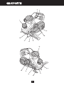
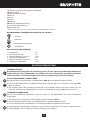
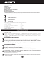
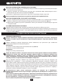
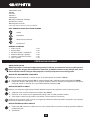
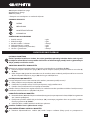
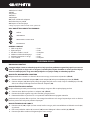
OPIS STRON GRAFICZNYCH
Poniższa numeracja odnosi się do elementów urządzenia przedstawionych na stronach gracznych
niniejszej instrukcji.
1. Pokrętło regulacji głębokości skrawania
2. Włącznik
3. Przycisk blokady włącznika
4. Osłona paska napędowego
5. Króciec odprowadzania pyłu
6. Stopa przednia
7. Podziałka głębokości skrawania
8. Pokrętło blokady ustawienia prowadnicy równoległej
9. Prowadnica równoległa
10. Wspornik
11. Pokrętło blokady wspornika
12. Prowadnica do strugania wgłębnego
13. Pokrętło blokady prowadnicy do strugania wgłębnego

7
14. Uchwyt prowadzący
15. Śruby mocujące
16. Nóż
17. Głowica
18. Rowek V
19. Adapter
20. Przycisk blokady adaptera
21. Osłona uchylna
22. Stopka parkująca
* Mogą występować różnice między rysunkiem a wyrobem.
OPIS UŻYTYCH ZNAKÓW GRAFICZNYCH
UWAGA
OSTRZEŻENIE
MONTAŻ/USTAWIENIA
INFORMACJA
WYPOSAŻENIE I AKCESORIA
1. Worek na pył - 1 szt
2. Klucz płaski - 1 szt
3. Prowadnica równoległa + wspornik - 1 kpl
4. Prowadnica do strugania wgłębnego - 1 szt
5. Adapter (zamontowany do struga) - 1 szt
6. Śruba + pokrętła - 1 kpl
PRZYGOTOWANIE DO PRACY
ODPROWADZANIE PYŁU
Strug posiada system odprowadzania pyłu, który zapobiega nadmiernemu nagromadzeniu się pyłu
w miejscu pracy. W przypadku długiej pracy strugiem przy materiałach, których obróbce towarzyszy
powstawanie pyłu szkodliwego dla zdrowia strug powinien być podłączony do zewnętrznego
urządzenia odsysania pyłu.
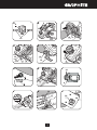
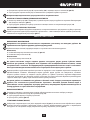
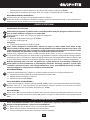
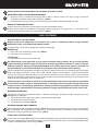
MONTAŻ / DEMONTAŻ ADAPTERA
Adapter może być montowany po prawej lub lewej stronie struga w zależności od potrzeb (rys. A).
●Wcisnąć przycisk blokady adaptera (20) i wysunąć adapter (19) z króćca odprowadzania pyłu (5) (rys. B).
●Wsunąć adapter (19) (zwracając uwagę, aby jego występ trał w prowadzenie) do króćca odprowadzania
pyłu (5) do słyszalnego zaskoczenia przycisku blokady adaptera (20).
MONTAŻ WORKA NA PYŁ
Celem utrzymania czystości powierzchni obrabianej strug ma dołączony worek do gromadzenia pyłu.
●Wsunąć otwór worka na pył na adapter (19) (rys. C)
●Sprawdzić pewność osadzenia worka na pył przez lekkie pociągnięcie za worek.
●Demontaż worka na pył przebiega w odwrotnej kolejności do jego montażu.
Regularnie należy opróżniać worek na pył, co zapewnia wydajne działanie struga. Zaleca się opróżniać
worek na pył już po napełnieniu go w połowie.
MONTAŻ PROWADNICY RÓWNOLEGŁEJ
●Umieścić wspornik (10) w prowadzeniu (po lewej stronie) obudowy struga i zamocować pokrętłem
blokady wspornika (11) (w wyposażeniu).

8
●Zamocować prowadnicę równoległą (9) do wspornika (10) wykorzystując dostarczoną śrubę i pokrętło
(8) (rys. D).
●Ustawić prowadnicę równoległą na odpowiednią szerokość skrawania.
Listwa prowadząca prowadnicy równoległej powinna być skierowana do dołu.
MONTAŻ PROWADNICY DO STRUGANIA WGŁĘBNEGO
●Umieścić prowadnicę do strugania wgłębnego (12) w prowadzeniu (po prawej stronie) obudowy struga
i zamocować pokrętłem blokady prowadnicy (13) (w wyposażeniu) (rys. E).
●Ustawić głębokość skrawania korzystając z podziałki umieszczonej na prowadnicy do strugania
wgłębnego (12).
REGULACJA GŁĘBOKOŚCI SKRAWANIA
Stopa przednia (6) jest ruchoma, co pozwala na regulację głębokości skrawania.
Głębokość skrawania reguluje się pokrętłem regulacji głębokości skrawania (1) w zakresie od 0 – 3 mm
według podziałki głębokości skrawania (7) umieszczonej na jego obwodzie (rys. F).
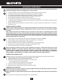
PRACA / USTAWIENIA
WŁĄCZANIE / WYŁĄCZANIE
Napięcie sieci musi odpowiadać wielkości napięcia podanego na tabliczce znamionowej struga.
Podczas uruchamiania i pracy strug należy trzymać obiema rękami.
Strug posiada włącznik zabezpieczający przed przypadkowym uruchomieniem.
Włączanie:
●Wcisnąć przycisk blokady włącznika (3) (rys. G).
●Wcisnąć przycisk włącznika (2).
Wyłączanie:
●Zwolnić nacisk na przycisk włącznika (2).
Przed włączeniem struga należy uchwycić go pewnie obiema rękami. Strug można włączać tylko
wtedy, gdy stopa przednia jest oparta na materiale przewidzianym do obróbki, a noże struga nie
dotykają materiału. Takie umieszczenie zapobiega przedwczesnemu zetknięciu noży z materiałem.
Pracę można rozpocząć dopiero wtedy, gdy strug osiągnie maksymalną prędkość obrotową.
W czasie posługiwania się strugiem należy dążyć do równoległego usytuowania powierzchni stopy struga
i powierzchni materiału obrabianego. Strug należy prowadzić obiema rękami przy równomiernym ciągłym
posuwie po powierzchni materiału. Rezultaty pracy zależą od prędkości przesuwu struga i głębokości
skrawania. Prace zgrubne wykonuje się stosując większą głębokość skrawania. Przy wygładzaniu
powierzchni zaleca się ustawiać niewielkie głębokości obróbki i pracę wykonywać kilkoma operacjami.
Nie wolno dociskać struga zbyt silnie. Nacisk powinien być umiarkowany i rozłożony równomiernie
na powierzchnię styku stopy z materiałem obrabianym. Wywieranie zbyt dużego nacisku na strug
spowoduje nienormalny spadek prędkości obrotowej, nadmierne nagrzewanie silnika, uszkodzenie
materiału obrabianego i elementów struga. Stosować okresowe przerwy w pracy.
STRUGANIE WGŁĘBNE
Dzięki możliwości użycia prowadnicy do strugania wgłębnego i prowadnicy równoległej można wykonywać
zagłębienia w materiale.
●Zamocować prowadnicę równoległą (9) i prowadnicę do strugania wgłębnego (12).
●Ustawić szerokość i głębokość skrawania.
●Wykonać obróbkę materiału (rys. H).
OBRÓBKA NAROŻY FAZOWANIE
Umieszczone rowki V (18) na stopie przedniej (6) (rys. I) umożliwiają szybką obróbkę (fazowanie), krawędzi
obrabianego materiału. Umieścić jeden z rowków V na krawędzi materiału obrabianego i prowadzić strug
do przodu zwracając uwagę na ustawienie kąta 450 (rys. J).

9
STOPKA PARKUJĄCA
Stopka parkująca (22) umożliwia bezpieczne odłożenie struga podczas pracy, bez ryzyka uszkodzenia
powierzchni przedmiotu obrabianego lub noży struga. Podczas obróbki stopka parkująca (22) unosi się do
góry i zwalnia tylną stopę struga (rys. L).
OBSŁUGA I KONSERWACJA
Przed przystąpieniem do jakichkolwiek czynności związanych z instalowaniem, regulacją, naprawą
lub obsługą należy wyjąć wtyczkę przewodu zasilającego z gniazdka sieciowego.
●Strug najlepiej czyścić za pomocą miękkiej szczotki lub strumienia sprężonego powietrza.
●Do czyszczenia struga nie wolno używać jakichkolwiek przedmiotów ściernych.
●Do czyszczenia nie wolno stosować wody lub chemicznych środków czyszczących.
●Czyścić strug regularnie, a najlepiej po zakończeniu każdej pracy.
●Strug i jego szczeliny wentylacyjne należy zawsze utrzymywać w czystości.
●Strug zawsze należy przechowywać w miejscu suchym, niedostępnym dla dzieci.
●W przypadku występowania nadmiernego iskrzenia na komutatorze zlecić sprawdzenie stanu szczotek
węglowych silnika osobie wykwalikowanej.
●Po zakończeniu pracy należy opróżnić worek na pył, umyć w ciepłej wodzie z mydłem i starannie
wysuszyć.
WYMIANA NOŻY STRUGA
Należy stosować wyłącznie głowice tnące zalecane przez producenta, które obejmują noże,
bęben, elementy mocowania noży, odpowiednie śruby i wrzeciono. Zawsze dokonuje się wymiany
jednocześnie obu noży.
Nowe noże muszą być takiej samej wielkości i mieć taką samą masę jak noże stare. W przeciwnym
wypadku głowica może zacząć drgać, obróbka będzie przebiegać niewłaściwie i może dojść do
uszkodzenia noży lub głowicy struga. Zbyt duży posuw znacznie redukuje wydajność i jakość pracy
oraz trwałość noży. Należy używać tylko ostrych noży. Chronić strug przed stępieniem noży. Noże
należy wymieniać jak tylko zaistnieje taka potrzeba.
●Poluzować śruby mocujące (15) nóż (16) za pomocą klucza ( w wyposażeniu) (rys. K).
●Obrócić głowicę (17) o pół obrotu i powtórzyć ten zabieg dla drugiego noża.
●Wcisnąć osłonę uchylną (21) i wysunąć noże.
●Wymienić noże na nowe i zamontować w kolejności odwrotnej do ich demontażu.
●Upewnić się czy noże są umieszczone symetrycznie w prowadnicy głowicy (17).
●Dokręcić śruby mocujące (15) równomiernie i na przemian.
Po zamontowaniu noży w głowicy należy pamiętać, aby wkręty i śruby były pewnie dokręcone. Ich
nie dokręcenie może być powodem uszkodzenia struga lub ciała użytkownika. Ostrza noży muszą
być równoległe do powierzchni walca głowicy. W przeciwnym razie obrabiana powierzchnia nie
będzie płaska i równa. Należy stosować wyłącznie głowicę, która jest dostarczana łącznie z wyrobem
lub dostarczoną przez wytwórcę albo jego autoryzowanego dystrybutora.
WYMIANA PASKA NAPĘDOWEGO
Jeśli pasek napędowy jest zużyty to strug nie pracuje właściwie. Konieczna jest wymiana paska
napędowego.
●Odkręcić wkręty mocujące i zdjąć osłonę paska napędowego (4).
●Zdjąć pasek napędowy zsuwając go z kół poprzez obracanie kół ręką.
●Montaż nowego paska napędowego należy przeprowadzić w następujący sposób:
–założyć pasek napędowy na mniejsze koło.
–obracając kołami nasunąć pasek napędowy na większe koło.
●Upewnić się czy pasek jest dobrze ułożony na obu kołach.
●Zamontować osłonę paska napędowego (4) dokręcając wkręty mocujące.

10
WYMIANA SZCZOTEK WĘGLOWYCH
Zużyte (krótsze niż 5 mm), spalone lub pęknięte szczotki węglowe silnika należy natychmiast
wymienić. Zawsze dokonuje się jednocześnie wymiany obu szczotek węglowych.
Czynność wymiany szczotek węglowych należy powierzyć wyłącznie osobie wykwalikowanej
wykorzystując części oryginalne.
Wszelkiego rodzaju usterki powinny być usuwane przez autoryzowany serwis producenta.
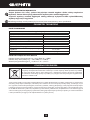
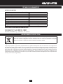
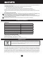
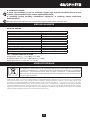
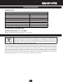
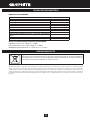
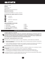
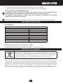
PARAMETRY TECHNICZNE
DANE ZNAMIONOWE
Strug elektryczny
Parametr Wartość
Napięcie zasilania 230 V AC
Częstotliwość zasilania 50 Hz
Moc znamionowa 850 W
Prędkość obrotowa na biegu jałowym 16500 min-1
Klasa ochronności II
Ilość noży 2
Szerokość planowania 82 mm
Głębokość obróbki przy planowaniu 0 - 3 mm
Max.głębokość obróbki przy struganiu
wgłębnym 0 - 12 mm
Masa 3,1 kg
Rok produkcji 2019
DANE DOTYCZĄCE HAŁASU I DRGAŃ
Poziom ciśnienia akustycznego: LpA = 93,7 dB(A) K = 3 dB(A)
Poziom mocy akustycznej: LwA = 104,7 dB(A) K = 3 dB(A)
Wartość przyspieszeń drgań: ah = 3,987 m/s2 K = 1,5 m/s2
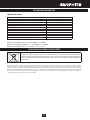
OCHRONA ŚRODOWISKA
Produktów zasilanych elektrycznie nie należy wyrzucać wraz z domowymi odpadkami, lecz oddać je
do utylizacji w odpowiednich zakładach. Informacji na temat utylizacji udzieli sprzedawca produktu
lub miejscowe władze. Zużyty sprzęt elektryczny i elektroniczny zawiera substancje nieobojętne
dla środowiska naturalnego. Sprzęt nie poddany recyclingowi stanowi potencjalne zagrożenie dla
środowiska i zdrowia ludzi.
* Zastrzega się prawo dokonywania zmian.
„Grupa Topex Spółka zograniczoną odpowiedzialnością” Spółka komandytowa zsiedzibą wWarszawie, ul. Pograniczna
2/4 (dalej: „Grupa Topex”) informuje, iż wszelkie prawa autorskie do treści niniejszej instrukcji (dalej: „Instrukcja”), wtym
m.in. jej tekstu, zamieszczonych fotograi, schematów, rysunków, atakże jej kompozycji, należą wyłącznie do Grupa Topex
ipodlegają ochronie prawnej zgodnie zustawą zdnia 4 lutego 1994 roku, oprawie autorskim iprawach pokrewnych (tj.
Dz. U. 2006 Nr 90 Poz 631 zpóźn. zm.). Kopiowanie, przetwarzanie, publikowanie, modykowanie wcelach komercyjnych
całości Instrukcji jak iposzczególnych jej elementów, bez zgody Grupa Topex wyrażonej na piśmie, jest surowo zabronione
imoże spowodować pociągnięcie do odpowiedzialności cywilnej ikarnej.

11
GWARANCJA I SERWIS
Warunki gwarancji oraz opis postepowania w przypadku reklamacji zawarte są w załączonej Karcie
Gwarancyjnej.
Serwis Centralny
GTX Service tel. +48 22 573 03 85
Ul. Pograniczna 2/4 fax. +48 22 573 03 83
02-285 Warszawa e-mail [email protected]
Sieć Punktów Serwisowych do napraw gwarancyjnych i pogwarancyjnych dostępna na platformie
internetowej gtxservice.pl
GRAPHITE zapewnia dostępność części zamiennych oraz materiałów eksploatacyjnych dla urządzeń
i elektronarzędzi. Pełna oferta części i usług na gtxservice.pl.
Zeskanuj QR kod i wejdź na gtxservice.pl

12
Deklaracja Zgodności WE
/EC Declaration of Conformity/
/Megfelelőségi Nyilatkozat EK/
/ES vyhlásenie o zhode/
PL EN HU SK
Producent
/Manufacturer//Gyártó//Výrobca/
Grupa Topex Sp. z o.o. Sp.k.
ul. Pograniczna 2/4, 02-285 Warszawa
Wyrób
/Product/
/Termék/
/Produkt/
Strug elektryczny
/Electric Planer/
/Elektromos Kézigyalu/
/Elektrické hoblíky/
Model
/Model//Modell//Model/ 59G678
Numer seryjny
/Serial number//Sorszám//Poradové číslo/ 00001 ÷ 99999
Opisany wyżej wyrób jest zgodny z następującymi dokumentami:
/The above listed product is in conformity with the following UE Directives:/
/A fent jelzett termék megfelel az alábbi irányelveknek:/
/Vyššie popísaný výrobok je v zhode s nasledujúcimi dokumentmi:/
Dyrektywa Maszynowa 2006/42/WE
/Machinery Directive 2006/42/EC/
/2006/42/EK Gépek/
/Smernica Európskeho Parlamentu a Rady 2006/42/ES/
Dyrektywa o Kompatybilności Elektromagnetycznej 2014/30/UE
/EMC Directive 2014/30/EU/
/2014/30/EU Elektromágneses összeférhetőség/
/EMC Smernica Európskeho Parlamentu a Rady 2014/30/EÚ/
Dyrektywa o RoHS 2011/65/UE
/RoHS Directive 2011/65/EU/
/RoHS irányelv 2011/65/EU/
/RoHS Smernica Európskeho Parlamentu a Rady 2011/65/EÚ/
oraz spełnia wymagania norm:
/and fulls requirements of the following Standards:/
/valamint megfelel az alábbi szabványoknak:/
/a spĺňa požiadavky:/
EN 60745-1:2009+A11:2010; EN 60745-2-14:2009+A2:2010;
EN 55014-1:2006/A2:2011; EN 55014-2:1997/A2:2008; EN 61000-3-2:2014; EN 61000-3-3:2013;
EN 62321:2009
Jednostka notykowana: /Noied body//Bejelentett szervezet//Notikovaný organ/
No. 0197; TŰV Rheinland LGA Products GmbH, Tillystraße 2, 90431 Nürnberg, Niemcy
Nazwisko i adres osoby mającej miejsce zamieszkania lub siedzibę w UE upoważnionej do przygotowania dokumentacji technicznej:
/Name and address of the person who established in the Community and authorized to compile the technical le:/
/A műszaki dokumentáció összeállítására felhatalmazott, a közösség területén lakóhellyel vagy székhellyel rendelkező személy neve és címe:/
/Meno a adresa osoby alebo bydliska v EÚ poverená zostavením technickej dokumentácie:/
Paweł Kowalski
Ul. Pograniczna 2/4
02-285 Warszawa
Paweł Kowalski
Pełnomocnik ds. jakości rmy GRUPA TOPEX
/GRUPA TOPEX Quality Agent/
/A GRUPA TOPEX Minőségügyi meghatalmazott képviselője/
/Splnomocnenec Kvalita TOPEX GROUP/
Warszawa, 2018-07-04

13
TRANSLATION OF THE ORIGINAL INSTRUCTIONS
ELECTRIC PLANER
59G678
CAUTION: BEFORE USING THE POWER TOOL READ THIS MANUAL CAREFULLY AND KEEP IT FOR FUTURE
REFERENCE.
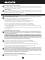
DETAILED SAFETY REGULATIONS
SPECIAL CONDITIONS REGARDING SAFETY OF ELECTRIC PLANER OPERATION
●Before connecting the planer to mains socket make sure the supply voltage matches the voltage on the
rating plate of the tool.
●Connect the planer only to electrical system equipped with residual current circuit breaker that will cut
the power o when earth leakage current exceeds 30 mA in less than 30 ms.
●Use only sharp cutting parts.
●After the work has been nished and before putting the planer away wait until rotating parts stop
completely.
●Use hearing protection measures when working with planer.
●When using the planer hold it rmly with both hands.
●Power cord of the planer must be on the safe side, where there is no danger of accidental damage by
operating power tool.
●Before starting operation ensure there are no metal objects, such as nails or screws, in the processed
material.
●Do not put ngers into dust outlet hole. Clean the outlet with a piece of wood.
●Fix processed material to prevent it from slipping.
CAUTION! This device is designed to operate indoors.
The design is assumed to be safe, protection measures and additional safety systems are used,
nevertheless there is always a small risk of operational injuries.
CONSTRUCTION AND USE
Planer is a hand-held power tool with insulation class II. The tool is driven by single-phase commutator
motor. Planer is designed for processing wooden surfaces.
Range of use covers repair and building works, woodworking and any work from the scope of individual,
amateur activities (tinkering).
Use the power tool according to the manufacturer’s instructions only.
DESCRIPTION OF DRAWING PAGES
Below enumeration refers to the device elements depicted on the drawing pages of this manual.
1. Knob for planing depth adjustment
2. Switch
3. Switch lock button
4. Drive belt cover
5. Dust extraction outlet
6. Front footplate
7. Planing depth scale
8. Parallel guide position locking wheel
9. Parallel guide
10. Support
11. Support locking knob
12. Deep planing guide
13. Locking knob for deep planing guide
14. Guide handle
15. Fixing screws

14
16. Blade
17. Head
18. V groove
19. Adaptor
20. Adaptor lock button
21. Removable shield
22. Park rest
* Dierences may appear between the product and drawing.
MEANING OF SYMBOLS
CAUTION
WARNING
ASSEMBLY/SETTINGS
INFORMATION
EQUIPMENT AND ACCESSORIES
1. Dust bag - 1 pce
2. Flat spanner - 1 pce
3. Parallel guide + support - 1 set
4. Deep planing guide - 1 pce
5. Adaptor (attached to planer) - 1 pce
6. Screw + knobs - 1 set
PREPARATION FOR OPERATION
DUST EXTRACTION
Planer is equipped with dust extraction system, which prevents excessive deposition of dust in the
work place. When operating the planer for a long time on the surfaces that produce harmful dust,
the planer must be connected to external dust suction device.
INSTALLATION / DEINSTALLATION OF ADAPTOR
Depending on the needs, adaptor can be attached on left or right side of the planer (g. A).
●Press the adaptor lock button (20) and pull the adaptor (19) out of the dust extraction outlet (5) (g. B).
●Slide the adaptor (19) into the dust extraction outlet (5) (be careful to place protrusion in the notch),
make sure you can hear the adaptor lock button (20) snaps.
DUST BAG INSTALLATION
Equipment of the planer includes dust bag to maintain the processed surface clean.
●Place the dust bag hole on the adaptor (19) (g. C).
●Pull the dust bag gently to check if it is well xed.
●Deinstallation of the dust bag is similar to installation, only the sequence of actions is reversed.
Empty the dust bag on a regular basis, this will ensure ecient operation of the planer. Emptying the bag
when it is half-full is recommended.
PARALLEL GUIDE INSTALLATION
●Place the support (10) in the guide (on the left side) in the planer body and secure with support locking
knob (11) (included).
●Use the supplied screw and locking wheel (8) to attach parallel guide (9) to the support (10) (g. D).
●Set parallel guide to appropriate planing width.
Parallel guide bar should be pointed downwards.

15
INSTALLATION OF DEEP PLANING GUIDE
●Place the deep planing guide (12) in the guide (on the right side) in the planer body and secure with the
locking knob for deep planing guide (13) (included) (g. E).
●Use the scale on the deep planing guide (12) to set planing depth.
PLANING DEPTH ADJUSTMENT
Planer front footplate (6) is movable and it allows for planing depth adjustment.
Planing depth can be adjusted with the knob for planing depth adjustment (1) and the range is 0 – 3 mm,
shown on the planing depth scale (7) located on its circumference (g. F).
OPERATION / SETTINGS
SWITCHING ON / SWITCHING OFF
The mains voltage must match the voltage on the rating plate of the planer. Hold the planer with
both hands when starting up and during operation.
The planer features switch that protects against unintentional starting up.
Switching on:
●Press the switch lock button (3) (g. G).
●Press the switch button (2).
Switching o:
●Release pressure on the switch button (2).
Hold the planer rmly with both hands before switching it on. Switch on the planer only when the
front footplate rests on the material that you plan to process and the planer blades do not touch
material. This position prevents too early contact of blades with material. Start the work only after
the planer reaches its top rotational speed.
When using the planer, try to position planer footplate and surface of processed material in parallel. Guide the
planer with both hands, move it smoothly and continuously on the material surface. Eects of work depend
on speed of planer movement and depth of planing. Coarse processing uses bigger planing depth. During
ne processing it is recommended to set small planing depth and to proceed with work in few runs.
Do not press the planer too hard. Pressure should be moderate and uniform on the whole surface
of contact of foot and processed material. Applying too big pressure causes undesirable drop of
rotational speed, motor overheating, damage of processed material and parts of the planer. Make
periodic breaks in operation.
DEEP PLANING
You can use the deep planing guide and the parallel guide to make hollows in material.
●Attach the parallel guide (9) and the deep planing guide (12).
●Set planing width and depth.
●Process the material (g. H).
PROCESSING CORNERS CHAMFERING
V-grooves (18) located on the front footplate (6) (g. I) allow for quick processing (chamfering) of edges
of processed material. Place one of the V-grooves on the edge of processed material and move the planer
forward, make sure to keep the 450 angle (g. J).
PARK REST
Park rest (22) allows to put away the planer safely during operation without the risk of damaging processed
surface or the planer blades. The park rest (22) lifts up when processing and releases the back footplate of
the planer (g. L).

16
OPERATION AND MAINTENANCE
Unplug the power cord from mains socket before commencing any activities related to installation,
adjustment, repair or maintenance.
●Soft brush or compressed air are best for cleaning the planer.
●Do not use abrasive objects for cleaning the planer.
●Do not clean with water or chemical cleaning agents.
●Clean the planer regularly, optimally after each use.
●Always keep the planer and ventilation holes clean.
●Store the planer in dry place, beyond reach of children.
●In case of excessive commutator sparking, have the technical condition of carbon brushes of the motor
checked by a qualied person.
●When the work is nished empty the dust bag, next wash it in warm water with soap and dry it
thoroughly.
REPLACEMENT OF PLANER BLADES
Use only cutting heads that are recommended by the manufacturer, and that include blades, drum,
blade xing parts, appropriate bolts and spindle. Always replace both blades at a time.
New blades must be of the same size and weight as old ones. Otherwise the head may vibrate,
processing may be improper and it may damage blades or planer head. Too fast advance considerably
reduces eciency and quality of work and durability of blades. Use only sharp blades. Avoid blunting
the blades. Replace blades as soon as it is necessary.
●Use the spanner (included) to loosen xing screws (15) of the blade (16) (g. K).
●Turn the head (17) by 1800 and repeat this operation for the second blade.
●Press in the removable shield (21) and slide the blades out.
●Replace the blades with new ones and proceed with installation in reverse sequence of disassembly.
●Make sure the blades are positioned symmetrically in the guide of the head (17).
●Tighten screws (15) that x blades alternately and with the same force.
Ensure screws and bolts are tightened after blades are installed in the head. Failing to do so may
cause damage of the planer or the user’s body injury. Blade edges must be parallel to the head drum
surface. Otherwise the processed surface will not be at and even. Use only head that is supplied
with the product, head supplied by the manufacturer or its authorized distributor.
REPLACEMENT OF DRIVE BELT
Planer does not work properly if drive belt is worn. Belt replacement is necessary.
●Unscrew xing screws and remove the drive belt cover (4).
●Remove the drive belt by turning the pulleys manually and pulling the belt o.
●To install new drive belt do as follows:
- put the drive belt onto smaller pulley,
- rotate pulleys and draw the drive belt over the bigger pulley.
●Ensure the belt is correctly set on both pulleys.
●Install drive belt cover (4) and tighten xing screws.
REPLACEMENT OF CARBON BRUSHES
Replace immediately worn out (shorter than 5 mm), burnt or cracked motor carbon brushes. Always
replace both carbon brushes at a time.
Entrust replacement of carbon brushes only to a qualied person. Only original parts should be
used.
All faults should be repaired by service workshop authorized by the manufacturer.

17
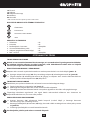
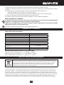
TECHNICAL PARAMETERS
RATED PARAMETERS
Electric Planer
Parameter Value
Supply voltage 230 V AC
Input current frequency 50 Hz
Rated power 850 W
Idle rotational speed 16500 rmp
Protection class II
Number of blades 2
Planing width 82 mm
Processing depth for planing 0 - 3 mm
Max. processing depth for deep planing 0 - 12 mm
Weight 3,1 kg
Year of production 2019
NOISE LEVEL AND VIBRATION PARAMETERS
Sound pressure: LpA = 93,7 dB(A) K = 3 dB(A)
Sound power: LwA = 104,7 dB(A) K = 3 dB(A)
Vibration acceleration: ah = 3,987 m/s2. K = 1,5 m/s2
ENVIRONMENT PROTECTION
Do not dispose of electrically powered products with household wastes, they should be utilized in
proper plants. Obtain information on wastes utilization from your seller or local authorities. Used up
electric and electronic equipment contains substances active in natural environment. Unrecycled
equipment constitutes a potential risk for environment and human health.
* Right to introduce changes is reserved.
“Grupa Topex Spółka z ograniczoną odpowiedzialnością” Spółka komandytowa with seat in Warsaw at ul. Pograniczna
2/4 (hereinafter Grupa Topex) informs, that all copyrights to this instruction (hereinafter Instruction), including, but not
limited to, text, photographies, schemes, drawings and layout of the instruction, belong to Grupa Topex exclusively and are
protected by laws accordingly to Copyright and Related Rights Act of 4 February 2004 (ustawa o prawie autorskim i prawach
pokrewnych, Dz. U. 2006 No 90 item 631 with later ammendments). Copying, processing, publishing, modications for
commercial purposes of the entire Instruction or its parts without written permission of Grupa Topex are strictly forbidden
and may cause civil and legal liability.

18
ÜBERSETZUNG DER ORIGINALBETRIEBSANLEITUNG
ELEKTROHOBEL
59G678
ANMERKUNG: LESEN SIE VOR DER INBETRIEBNAHME DIESES ELEKTROWERKZEUGS GRÜNDLICH DIE
VORLIEGENDE BETRIEBSANLEITUNG DURCH UND BEWAHREN SIE SIE AUF.
DETAILLIERTE SICHERHEITSVORSCHRIFTEN
DETAILLIERTE SICHERHEITSHINWEISE FÜR DEN ELEKTROHOBEL
●Vor dem Anschließen des Elektrohobels ans Netz prüfen Sie stets, dass die Netzspannung der auf dem
Typenschild angegebenen Nennspannung des Gerätes entspricht.
●Der Elektrohobel ist nur an die Stromleitung mit dem Dierenzstromschutz anzuschließen, die
Versorgung unterbrechen wird, falls der Leckstrom 30 mA innerhalb von 30 ms überschreiten wird.
●Nur scharfe Schneidelemente verwenden.
●Bevor Sie den Elektrohobel ablegen, warten Sie ab, bis die rotierenden Elemente zum kompletten
Stillstand kommen.
●Beim Gebrauch des Elektrohobels ist der Gehörschutz zu tragen.
●Der Elektrohebel ist beim Betrieb mit beiden Händen festzuhalten.
●Halten Sie stets die Netzanschlussleitung des Elektrohobels auf der sicheren Seite, damit sie mit dem
Elektrogerät nicht zufällig beschädigt wird.
●Vor dem Betrieb stellen Sie sicher, dass sich im Werkstück keine Metallelemente wie Nagel oder
Schrauben benden.
●Halten Sie nie Ihre Finger in der Önung des Staubabsaugstutzens. Reinigen Sie den Stutzen mit einem
Holzstück.
●Befestigen Sie das Werkstück, damit es nicht verschoben wird.
ACHTUNG! Das Gerät ist für den Betrieb in Innenräumen bestimmt.
Trotz des Einsatzes einer sicheren Konstruktion, von Sicherheitseinrichtungen und zusätzlichen
Schutzeinrichtungen besteht stets das Restrisiko einer Verletzung beim Betrieb des Gerätes.
AUFBAU UND BESTIMMUNG
Der Elektroschleifer ist ein manuell betriebenes Elektrowerkzeug mit der II. Isolierklasse. Das Gerät wird
mit einem einphasigen Kommutatormotor betrieben. Der Elektrohobel ist für die Zerspanung von
Holzerzeugnissen bestimmt.
Der Anwendungsbereich dieses Werkzeugs umfasst die Ausführung von Sanierungs- und Bauarbeiten,
Tischlerarbeiten und aller Arbeiten, die Zuhause selbst durchgeführt werden (Heimwerker).
Nichtbestimmungsgemäße Verwendung des Elektrowerkzeugs ist nicht zugelassen.
BESCHREIBUNG DER SEITEN MIT GRAPHIKEN
Die unten angeführte Nummerierung bezieht sich auf die Elemente des Gerätes, die auf den Seiten mit
Graphiken dargestellt werden.
1. Einstellring für Zerspanungstiefe
2. Hauptschalter
3. Taste der Schalterverriegelung
4. Abdeckung des Antriebsriemens
5. Staubabsaugstutzen
6. Vorderer Gerätefuß
7. Skala der Bearbeitungstiefe
8. Drehknopf für Einstellsperre der parallelen Führung
9. Parallele Führung
10. Tragarm
11. Drehknopf für Tragarmverriegelung
12. Führung für Tiefhobeln

19
13. Arretierungsring der Führung zum Tiefhobeln
14. Führungsgri
15. Befestigungsschrauben
16. Messer
17. Kopf
18. V-Nut
19. Adapter
20. Taste der Adapterarretierung
21. Schwenkbare Abdeckung
22. Positionierfuß
* Es können Unterschiede zwischen der Abbildung und dem Produkt auftreten.
BESCHREIBUNG FÜR VERWENDETE GRAPHISCHE ZEICHEN
ACHTUNG
WARNUNG
MONTAGE/EINSTELLUNGEN
INFORMATION
AUSSTATTUNG UND ZUBEHÖR
1. Staubbeutel - 1 St.
2. Schraubenschlüssel - 1 St.
3. Parallele Führung + Tragarm - 1 Satz
4. Führung für Tiefhobeln - 1 St.
5. Adapter (am Hobel montiert) - 1 St.
6. Schraube + Drehknöpfe - 1 Satz
BETRIEBSVORBEREITUNG
STAUBABFÜHRUNG
Der Elektrohobel verfügt über das Staubsaugsystem, das den Staub vom Arbeitsplatz ableitet. Bei
langem Gebrauch des Elektrohobels mit Stoen, bei deren Bearbeitung gesundheitsschädliche
Stäube entstehen, ist der Elektrohobel an ein äußeres Staubabsaugsystem anzuschließen.
ADAPTER MONTIEREN / DEMONTIEREN
Der Adapter kann links oder rechts am Elektrohobel (Abb. A) je nach Bedarf montiert werden.
●Die Taste der Adapterarretierung (20) drücken und den Adapter (19) vom Staubabsaugstutzen (5) (Abb.
B) herausziehen.
●Den Adapter (19) in den Staubabsaugstutzen (5) so einschieben (dabei ist darauf zu achten, dass die
Rastnase auf die Nut im Stutzen trit), dass die Taste der Adapterarretierung (20) hörbar einrastet.
STAUBBEUTEL MONTIEREN
Um die zu bearbeitende Oberäche sauber zu halten, ist der Elektrohobel mit einem Staubbeutel
ausgestattet.
●Die Önung des Staubbeutels auf den Adapter (19) aufschieben (Abb. C)
●Prüfen Sie durch leichtes Ziehen am Staubbeutel, ob er auf dem Adapter fest sitzt.
●Zum Demontieren des Staubbeutels ist das Montageverfahren umgekehrt anzuwenden.
Der Staubbeutel ist regelmäßig zu entleeren, um die richtige Funktionsweise des Hobels zu gewährleisten.
Es wird empfohlen, den Staubbeutel nach der Halbfüllung zu entleeren.

20
PARALLELE FÜHRUNG MONTIEREN
●Den Tragarm (10) in der Führung (links) am Gehäuse des Elektrohobels einlegen und mit dem Drehknopf
für Tragarmverriegelung (11) (mitgeliefert) montieren.
●Die parallele Führung (9) am Tragarm (10) mit der mitgelieferten Schraube und dem Drehknopf (8) (Abb.
D) anbringen.
●Die parallele Führung auf entsprechende Bearbeitungstiefe einstellen.
Die Leiste der parallelen Führung soll na unten zeigen.
FÜHRUNG ZUM TIEFHOBELN MONTIEREN
●Die Führung zum Tiefenhobeln (12) in die Führung (rechts) am Gehäuse des Elektrohobels einlegen und
mit dem Arretierungsring der Führung zum Tiefhobeln (13) (mitgeliefert) (Abb. E) montieren.
●Die Zerspanungstiefe mit der Skala an der Führung zum Tiefhobeln (12) einstellen.
REGULIERUNG DER BEARBEITUNGSTIEFE
Der vordere Gerätefuß (6) ist beweglich, was die Bearbeitungstiefe regulieren lässt.
Die Zerspanungstiefe wird mit dem Einstellring für Zerspanungstiefe (1) im Bereich von 0 bis 3 mm gemäß
der Skala für Zerspanungstiefe (7), die an seinem Umfang untergebracht ist, reguliert (Abb. F).
BETRIEB / EINSTELLUNGEN
EIN/AUSSCHALTEN
Die Netzspannung muss dem Spannungswert entsprechen, der im Typenschild des Elektrohobels
angegeben worden ist. Beim Start und Betrieb soll man den Elektrohobel in beiden Händen halten.
Der Elektrohobel verfügt über einen Sicherheitsschalter, der vor einem versehentlichen Start des Werkzeugs
schützt.
Einschalten:
●Die Taste der Schalterverriegelung (3) (Abb. G).
●Die Taste des Schalters (2) drücken.
Ausschalten:
●Den Schalter (2) freigeben.
Vor dem Einschalten des Elektrohobels halten Sie sie mit beiden Händen fest. Der Elektrohobel
darf nur dann eingeschaltet werden, wenn er auf dem Werkstück gestützt ist und die Messer des
Elektrohobels das Werkstück nicht berühren. Dies wird die vorzeitige Berührung der Messer mit
dem Werkstück verhindern. Der Betrieb kann nur dann begonnen werden, wenn der Motor des
Elektrohobels seine maximale Drehzahl erreichen wird.
Beim Gebrauch des Elektrohobels streben Sie nach einer parallelen Lage der Oberäche des Hobels und
des Werkstücks. Führen Sie den Elektrohobel mit beiden Händen und verschieben gleichmäßig an der
Oberäche des Werkstücks. Die Ergebnisse der Arbeit hängen von der Vorschubgeschwindigkeit des Hobels
und der Bearbeitungstiefe ab. Die Grobarbeiten werden bei der höheren Bearbeitungstiefe ausgeführt.
Beim Glätten der Oberäche empfehlen wir, geringe Bearbeitungstiefe einzustellen und die Bearbeitung
in mehreren Schritten auszuführen.
Drücken Sie den Elektrohobel nicht zu stark an. Der Andruck soll mittelmäßig und gleichmäßig auf
die Kontaktoberäche zwischen dem Gerätefuß und Werkstück verteilt sein. Der all zu starke Andruck
auf den Hobel wird einen untypischen Rückgang der Geschwindigkeit der Drehzahl, ein zu starkes
Aufheizen des Motors, die Beschädigung des Werkstücks und Maschinenelementen verursachen. Bei
der Arbeit legen Sie ab und zu Pausen ein.
TIEFHOBELN
Mit der Führung zum Tiefhobeln und der parallelen Führung können Vertiefungen im Werkstück ausgeführt
werden.
●Die parallele Führung (9) und die Führung zum Tiefhobeln (12) montieren.
●Die Zerspanungsbreite und –tiefe sind einzustellen.
●Das Werkstück bearbeiten (Abb. H).
Pagina se încarcă...
Pagina se încarcă...
Pagina se încarcă...
Pagina se încarcă...
Pagina se încarcă...
Pagina se încarcă...
Pagina se încarcă...
Pagina se încarcă...
Pagina se încarcă...
Pagina se încarcă...
Pagina se încarcă...
Pagina se încarcă...
Pagina se încarcă...
Pagina se încarcă...
Pagina se încarcă...
Pagina se încarcă...
Pagina se încarcă...
Pagina se încarcă...
Pagina se încarcă...
Pagina se încarcă...
Pagina se încarcă...
Pagina se încarcă...
Pagina se încarcă...
Pagina se încarcă...
Pagina se încarcă...
Pagina se încarcă...
Pagina se încarcă...
Pagina se încarcă...
Pagina se încarcă...
Pagina se încarcă...
Pagina se încarcă...
Pagina se încarcă...
Pagina se încarcă...
Pagina se încarcă...
Pagina se încarcă...
Pagina se încarcă...
Pagina se încarcă...
Pagina se încarcă...
Pagina se încarcă...
Pagina se încarcă...
Pagina se încarcă...
Pagina se încarcă...
Pagina se încarcă...
Pagina se încarcă...
Pagina se încarcă...
Pagina se încarcă...
Pagina se încarcă...
Pagina se încarcă...
Pagina se încarcă...
Pagina se încarcă...
Pagina se încarcă...
Pagina se încarcă...
Pagina se încarcă...
Pagina se încarcă...
Pagina se încarcă...
Pagina se încarcă...
Pagina se încarcă...
Pagina se încarcă...
Pagina se încarcă...
Pagina se încarcă...
Pagina se încarcă...
Pagina se încarcă...
Pagina se încarcă...
Pagina se încarcă...
Pagina se încarcă...
Pagina se încarcă...
Pagina se încarcă...
Pagina se încarcă...
Pagina se încarcă...
Pagina se încarcă...
Pagina se încarcă...
Pagina se încarcă...
Pagina se încarcă...
Pagina se încarcă...
Pagina se încarcă...
Pagina se încarcă...
Pagina se încarcă...
Pagina se încarcă...
Pagina se încarcă...
Pagina se încarcă...
Pagina se încarcă...
Pagina se încarcă...
Pagina se încarcă...
Pagina se încarcă...
Pagina se încarcă...
Pagina se încarcă...
Pagina se încarcă...
Pagina se încarcă...
-
 1
1
-
 2
2
-
 3
3
-
 4
4
-
 5
5
-
 6
6
-
 7
7
-
 8
8
-
 9
9
-
 10
10
-
 11
11
-
 12
12
-
 13
13
-
 14
14
-
 15
15
-
 16
16
-
 17
17
-
 18
18
-
 19
19
-
 20
20
-
 21
21
-
 22
22
-
 23
23
-
 24
24
-
 25
25
-
 26
26
-
 27
27
-
 28
28
-
 29
29
-
 30
30
-
 31
31
-
 32
32
-
 33
33
-
 34
34
-
 35
35
-
 36
36
-
 37
37
-
 38
38
-
 39
39
-
 40
40
-
 41
41
-
 42
42
-
 43
43
-
 44
44
-
 45
45
-
 46
46
-
 47
47
-
 48
48
-
 49
49
-
 50
50
-
 51
51
-
 52
52
-
 53
53
-
 54
54
-
 55
55
-
 56
56
-
 57
57
-
 58
58
-
 59
59
-
 60
60
-
 61
61
-
 62
62
-
 63
63
-
 64
64
-
 65
65
-
 66
66
-
 67
67
-
 68
68
-
 69
69
-
 70
70
-
 71
71
-
 72
72
-
 73
73
-
 74
74
-
 75
75
-
 76
76
-
 77
77
-
 78
78
-
 79
79
-
 80
80
-
 81
81
-
 82
82
-
 83
83
-
 84
84
-
 85
85
-
 86
86
-
 87
87
-
 88
88
-
 89
89
-
 90
90
-
 91
91
-
 92
92
-
 93
93
-
 94
94
-
 95
95
-
 96
96
-
 97
97
-
 98
98
-
 99
99
-
 100
100
-
 101
101
-
 102
102
-
 103
103
-
 104
104
-
 105
105
-
 106
106
-
 107
107
-
 108
108


în alte limbi
- slovenčina: Graphite 59G678 Návod na obsluhu
Alte documente
-
Ryobi EPN-6082 Manual de utilizare
-
Makita M1902 Manual de utilizare
-
Bosch GHO 15-82 Professional Instrucțiuni de utilizare
-
Bosch GHO 26-82 Instrucțiuni de utilizare
-
Bosch GHO 40-82 C Professional Instrucțiuni de utilizare
-
Bosch GHO 15-82 Specificație
-
EINHELL TE-PL 18/82 Li - Solo Manual de utilizare
-
-
 Raider Industrial RDI-EP14 Manual de utilizare
-
Maktec MT191 Manual de utilizare
