Master BMH 40-XES Translation Of The Original Instructions
- Categorie
- Ciocane rotative
- Tip
- Translation Of The Original Instructions
Acest manual este potrivit și pentru

BMH 40-XES
MH 5-XES
BMH 40-XES
MH 5-XES
Originalbetriebsanleitung
Translation of the Original Instructions
Traduzione delle istruzioni originali
Traduction de la notice originale
Traducción del manual original
Tradução das instruções de serviço originais
Vertaling van de oorspronkelijke
gebruiksaanwijzing
Oversættelse af den originale driftsvejledning
Oversettelse av original driftsinstruks
Alkuperäisen käyttöohjeen käännös
Översättning av bruksanvisning i original
Μετάραση των πρωττυπων δηγιών ειρισμύ
Orijinal iμletim talimat∂ tercümesi
TΔumaczenie oryginalnej instrukcji eksploatacji
Az eredeti kezelési útmutató fordítása
Pfieklad originálního návodu k provozu
Preklad originálneho Návodu na pouÏívanie
Traducerea instrucøiunilor de exploatare
originale
Prevod originalnega navodila za obratovanje
Превод на оригиналното ръководство за
експлоатация
Originaalkasutusjuhendi tõlge
Naudojimo instrukcijos originalo vertimas
Lietošanas pamācības oriināla tulkojums
Перевод оригинального руководства по
эксплуатации
0702 653 X - Titelseiten Seite 1 Montag, 12. Juli 2010 1:39 13

PL
H
CZ
SK
RO
SLO
BG
EST
LT
LV
RUS
D
GB
I
F
E
P
NL
DK
N
FIN
S
GR
TR
............................. 5… 9
............................. 10… 14
............................. 15… 19
............................. 20… 24
............................. 25… 29
............................. 30… 34
............................. 34… 39
............................. 40… 44
............................. 45… 49
............................. 50… 54
............................. 55… 59
............................. 60… 65
............................. 66… 70
............................. 71… 75
............................. 76… 80
............................. 81… 85
............................. 86… 90
............................. 91… 95
............................. 96…100
............................. 101…106
............................. 107…111
............................. 112…116
............................. 117…121
............................. 122…127
0702 653 X.book Seite 2 Freitag, 9. Juli 2010 9:37 09

1
2
3
4
5
6
7
8
9
10
11 13
BMH 40-XES
12
0702 653 X.book Seite 3 Freitag, 9. Juli 2010 9:37 09

1
2
3
4
5
6
9
12 11
MH 5-XES
0702 653 X - Bildseite 2 Seite 4 Montag, 12. Juli 2010 1:40 13

5
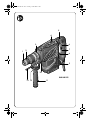
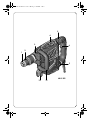
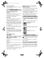
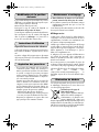
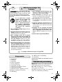
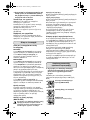
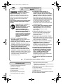
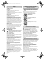
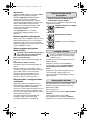
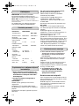
Geräteelemente
1 Staubschutzkappe
2 Verriegelungshülse für Bohrwerkzeug
3 Spannband
4 Betriebsartenwahlschalter
5 Vibrationsdämpfung
6 Ein-/Ausschalter
7 Arretierknopf Ein-/Ausschalter
8 Drehmomentumschalter
9 Stellrad Schlagzahlvorwahl/Drehzahlvorwahl
10 Knopf für Tiefenanschlagverstellung
11 Zusatzgriff
12 Rändelmutter für Zusatzgriff
13 Tiefenanschlag
Abgebildetes oder beschriebenes Zubehör gehört teilweise
nicht zum Lieferumfang.
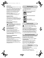
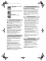
Lesen Sie alle Sicherheitshin-
weise und Anweisungen. Ver-
säumnisse bei der Einhaltung der Sicherheitshin-
weise und Anweisungen können elektrischen
Schlag, Brand und/oder schwere Verletzungen
verursachen.
Bewahren Sie alle Sicherheitshinweise und
Anweisungen für die Zukunft auf.
Gefahrloses Arbeiten mit dem
Gerät ist nur möglich, wenn Sie die
Bedienungsanleitung und die
Sicherheitshinweise vollständig
lesen und die darin enthaltenen
Anweisungen strikt befolgen.
Zusätzlich müssen die allgemeinen
Sicherheitshinweise im beigelegten
Heft befolgt werden.
❏ Tragen Sie Gehörschutz. Die Einwirkung von
Lärm kann Gehörverlust bewirken.
❏ Benutzen Sie mit dem Gerät gelieferte Zusatz-
handgriffe. Der Verlust der Kontrolle kann zu
Verletzungen führen.
❏ Halten Sie das Gerät an den isolierten Griffflä-
chen, wenn Sie Arbeiten ausführen, bei denen
das Einsatzwerkzeug verborgene Stromleitun-
gen oder das eigene Netzkabel treffen kann.
Der Kontakt mit einer spannungsführenden Lei-
tung kann auch metallene Geräteteile unter
Spannung setzen und zu einem elektrischen
Schlag führen.
❏ Verwenden Sie geeignete Suchgeräte, um ver-
borgene Versorgungsleitungen aufzuspüren,
oder ziehen Sie die örtliche Versorgungsge-
sellschaft hinzu. Kontakt mit Elektroleitungen
kann zu Feuer und elektrischem Schlag führen.
Beschädigung einer Gasleitung kann zur
Explosion führen. Eindringen in eine Wasserlei-
tung verursacht Sachbeschädigung oder kann
einen elektrischen Schlag verursachen.
❏ Halten Sie das Elektrowerkzeug beim Arbei-
ten fest mit beiden Händen und sorgen Sie für
einen sicheren Stand. Das Elektrowerkzeug
wird mit zwei Händen sicherer geführt.
❏ Sichern Sie das Werkstück. Ein mit Spannvor-
richtungen oder Schraubstock festgehaltenes
Werkstück ist sicherer gehalten als mit Ihrer
Hand.
❏ Halten Sie Ihren Arbeitsplatz sauber. Material-
mischungen sind besonders gefährlich. Leicht-
metallstaub kann brennen oder explodieren.
❏ Warten Sie, bis das Elektrowerkzeug zum
Stillstand gekommen ist, bevor Sie es ablegen.
Das Einsatzwerkzeug kann sich verhaken und
zum Verlust der Kontrolle über das Elektrowerk-
zeug führen.
❏ Benutzen Sie das Elektrowerkzeug nicht mit
beschädigtem Kabel. Berühren Sie das
beschädigte Kabel nicht und ziehen Sie den
Netzstecker, wenn das Kabel während des
Arbeitens beschädigt wird. Beschädigte Kabel
erhöhen das Risiko eines elektrischen Schlages.
❏ Nur Original Würth-Zubehör verwenden.
WARNUNG
D
☞
Weitere Sicherheitshinweise siehe Beilage.
Sicherheitshinweise für
Hämmer
0702 653 X.book Seite 5 Freitag, 9. Juli 2010 9:37 09

6
Bestimmungsgemäßer
Gebrauch
BMH 40-XES: Das Elektrowerkzeug ist bestimmt zum
Hammerbohren in Beton, Ziegel und Gestein sowie
für leichte Meißelarbeiten.
MH 5-XES: Das Elektrowerkzeug ist bestimmt für
Meißelarbeiten in Beton, Ziegel, Gestein und
Asphalt.
Für Schäden bei nicht bestimmungsgemäßen
Gebrauch haftet der Benutzer.
Fragen zum Gerät und seiner Anwendung beant-
wortet Ihnen in Deutschland die Produkt- und
Anwendungsberatung unter Tel.: 01805-60 65 69
(14 Cent/min).
Gerätekennwerte
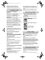
Zusatzgriff/Tiefenanschlag
❏ Vor allen Arbeiten am Gerät Netzstecker zie-
hen.
❏ Verwenden Sie Ihr Gerät nur mit dem Zusatz-
griff 11.
BMH 40-XES:
Lösen Sie das Griffstück durch Linksdrehen der Rän-
delmutter 12.
Sie können den Zusatzgriff 11 beliebig schwenken,
um eine sichere und ermüdungsarme Arbeitshaltung
zu erreichen.
Das Spannband 3 des Zusatzgriffs muss dabei in
der Nut bleiben.
Ziehen Sie das Griffstück danach durch Rechtsdre-
hen der Rändelmutter 12 wieder fest.
Stellen Sie mit dem Tiefenanschlag 13 die Bohrtiefe
ein.
Drücken Sie dazu die Taste für die Tiefenanschlag-
verstellung 10, stellen Sie die gewünschte Bohrtiefe
X ein und lassen die Taste wieder los.
Die Riffelung am Tiefenanschlag 13 muss nach
unten zeigen.
MH 5-XES:
Sie können den Zusatzgriff 11 beliebig schwenken,
um eine sichere und ermüdungsarme Arbeitshaltung
zu erreichen.
Lösen Sie die Rändelmutter 12, schwenken Sie den
Zusatzgriff 11 um die Geräteachse in die
gewünschte Position und ziehen Sie die Rändelmut-
ter 12 wieder fest.
Sie können den Zusatzgriff 11 ummontieren.
Schrauben Sie dazu die Rändelmutter 12 ganz ab
und ziehen Sie danach die Sechskantschraube nach
oben heraus. Ziehen Sie den Zusatzgriff 11 seitlich
ab und schwenken Sie das verbleibende Spannteil
um 180°. Montieren Sie den Zusatzgriff 11 in
umgekehrter Reihenfolge.
Werkzeugwechsel
❏ Vor allen Arbeiten am Gerät Netzstecker zie-
hen.
Mit der Werkzeugaufnahme SDS-max können Sie
das Einsatzwerkzeug einfach und bequem ohne
Verwendung zusätzlicher Werkzeuge wechseln.
Die Staubschutzkappe 1 verhindert weitgehend das
Eindringen von Bohrstaub in die Werkzeugauf-
nahme während des Betriebes. Achten Sie beim Ein-
setzen des Werkzeuges darauf, dass die Staub-
schutzkappe 1 nicht beschädigt wird.
❏ Eine beschädigte Staubschutzkappe ist sofort zu
ersetzen. Es wird empfohlen, dies von einem
Kundendienst vornehmen zu lassen.
Einsatzwerkzeug einsetzen
Reinigen Sie das Einsteckende des Einsatzwerkzeu-
ges und fetten Sie es leicht ein.
Setzen Sie das Einsatzwerkzeug drehend in die
Werkzeugaufnahme ein, bis es selbsttätig verriegelt
wird.
Überprüfen Sie die Verriegelung durch Ziehen am
Werkzeug.
Bohrhammer BMH 40-XES
Schlaghammer MH 5-XES
Artikelnummer 0702 553 X 0702 563 X
Nennaufnahmeleis-
tung
1300 W 1300 W
Einzelschlagstärke 2–12 J 2–12 J
Werkzeugaufnahme SDS-Max SDS-Max
Bohrleistung in Beton
- Vollbohrer
- Bohrkrone
12–45 mm
40–100 mm
–
–
Optimale Bohrleis-
tung in Beton
- Vollbohrer 25–35 mm –
Meißelstellungen 18 18
Gewicht, ca. 6,95 kg 6,2 kg
0702 653 X.book Seite 6 Freitag, 9. Juli 2010 9:37 09

7
Einsatzwerkzeug entnehmen
Schieben Sie die Verriegelungshülse 2 nach hinten
und entnehmen Sie das Einsatzwerkzeug.
Inbetriebnahme
Ein-/Ausschalten
MH 5-XES:
Zur Inbetriebnahme des Elektrowerkzeugs drücken
Sie den Ein-/Ausschalter 6.
Zum Ausschalten des Elektrowerkzeugs drücken Sie
den Ein-/Ausschalter 6 erneut.
BMH 40-XES:
Zur Inbetriebnahme des Elektrowerkzeugs drücken
Sie den Ein-/Ausschalter 6.
Zum Arretieren des Ein-/Ausschalters 6 halten Sie
diesen gedrückt und schieben zusätzlich den Arre-
tierknopf 7. Die Arretierung kann nur im Meißelbe-
trieb verwendet werden. Wird die Arretierung im
Bohrbetrieb aktiviert, schaltet sich das Elektrowerk-
zeug aus Sicherheitsgründen automatisch ab.
Zum Ausschalten des Elektrowerkzeugs drücken Sie
den Ein-/Ausschalter 6 und lassen ihn danach los.
Sanftanlauf
Der Sanftanlauf begrenzt die Drehzahl beim Ein-
schalten und steuert Sie danach automatisch hoch,
was z. B. ein ruckartiges Anlaufen beim Einsetzen
des Bohrers in ein bestehendes Loch verhindert.
Umschalten des Drehmoments
(BMH 40-XES)
Betätigen Sie den Drehmomentumschalter 8
nur bei Stillstand und wenn das Einsatzwerk-
zeug frei ist.
Niedriges Drehmoment:
Stellen Sie den Drehmomentumschalter 8 nach
oben.
Hohes Drehmoment:
Stellen Sie den Drehmomentumschalter 8 nach
unten.
Nach einer Stromunterbrechung springt der Dreh-
momentumschalter automatisch auf die Einstellung
„Niedriges Drehmoment“ zurück.
Diese Funktion mindert die Verletzungsgefahr da die
meisten Arbeiten mit der Einstellung „Niedriges
Drehmoment“ möglich sind.
Schlagzahl/Drehzahl einstellen
Die Regelelektronik ermöglicht eine stufenlose
Schlagzahl-/Drehzahlvorwahl für materialgerech-
tes Arbeiten.
Die Konstantelektronik hält die vorgewählte Schlag-
zahl-/Drehzahlvorwahl zwischen Leerlauf und Last-
betrieb nahezu konstant.
Wählen Sie die Schlagzahl-/Drehzahlvorwahl mit
dem Stellrad 9 dem Material entsprechend aus.
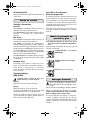
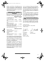
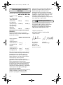
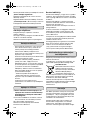
Schlag-/Drehstopp-Schalter
❏ Betätigen Sie den Schlag-/Drehstopp-Schalter 4
nur im Stillstand.
Schlag-/Drehstopp-Schalter 4 in die gewünschte Stel-
lung bringen:
Bohren/Hammerbohren (BMH 40-XES)
Meißelstellung verändern
Meißeln (Drehstopp)
Überlastkupplung
Klemmt oder hakt das Einsatzwerkzeug, wird
der Antrieb zur Bohrspindel unterbrochen.
(Auslösemoment der Kupplung: 40 Nm und 80 Nm)
Halten Sie, wegen der dabei auftretenden Kräfte,
das Elektrowerkzeug immer mit beiden Händen
gut fest und nehmen Sie einen festen Stand ein.
Blockiert das Bohrwerkzeug, das Gerät ausschalten
und Bohrwerkzeug lösen. Beim Einschalten mit blo-
ckiertem Bohrwerkzeug entstehen hohe Reaktions-
momente!
0702 653 X.book Seite 7 Freitag, 9. Juli 2010 9:37 09

8
Meißelstellung verändern
Der Meißel lässt sich in 18 Stellungen arretieren.
Dadurch kann die jeweils optimale Arbeitsstellung
eingenommen werden.
Setzen Sie den Meißel in die Werkzeugaufnahme
ein.
Drehen Sie den Schlag-/Drehstopp-Schalter 4 auf
„Meißelstellung verändern“.
Stellen Sie die Werkzeugaufnahme in die
gewünschte Meißelstellung.
Lassen Sie den Schlag-/Drehstopp-Schalter 4 auf
„Meißeln“ einrasten. Die Werkzeugaufnahme ist in
dieser Stellung arretiert.
Arbeitshinweise
Vibrationsdämpfung
Die integrierte Vibrationsdämpfung reduziert auftre-
tende Vibrationen.
Der Softgriff erhöht die Abrutschsicherheit und sorgt
dadurch für bessere Griffigkeit und Handlichkeit des
Elektrowerkzeuges.
Staubabsaugung
– Stäube von Materialien wie bleihaltigem
Anstrich, einigen Holzarten, Mineralien und
Metall können gesundheitsschädlich sein. Berüh-
ren oder Einatmen der Stäube können allergische
Reaktionen und/oder Atemwegserkrankungen
des Benutzers oder in der Nähe befindlicher Per-
sonen hervorrufen.
Bestimmte Stäube wie Eichen- oder Buchenstaub
gelten als krebserzeugend, besonders in Verbin-
dung mit Zusatzstoffen zur Holzbehandlung
(Chromat, Holzschutzmittel). Asbesthaltiges Mate-
rial darf nur von Fachleuten bearbeitet werden.
- Sorgen Sie für gute Belüftung des Arbeitsplat-
zes.
- Es wird empfohlen, eine Atemschutzmaske mit
Filterklasse P2 zu tragen.
Beachten Sie in Ihrem Land gültige Vorschriften
für die zu bearbeitenden Materialien.
Wartung und Pflege
❏ Vor allen Arbeiten am Gerät Netzstecker zie-
hen.
❏ Halten Sie das Elektrowerkzeug und die Lüftungs-
schlitze sauber, um gut und sicher zu arbeiten.
Das Elektrowerkzeug muss nach 150 Stunden vom
Würth master-Service gewartet werden.
Service-Anzeige
Die gelbe LED leuchtet auf, wenn die Kohlebürsten
fast abgenutzt sind. Nach weiteren 8 Betriebsstun-
den sind die Bürsten komplett verschlissen und der
Motor wird automatisch abgeschaltet.
Die rote LED leuchtet auf, wenn der Arretierknopf in
einer anderen Betriebsart als zum Meißeln verwen-
det wird. Die rote LED beginnt zu blinken, wenn eine
Störung am Elektrowerkzeug vorliegt oder die Bürs-
ten vollständig verschlissen sind.
Sollte das Gerät trotz sorgfältiger Herstell- und Prüf-
verfahren einmal ausfallen, ist die Reparatur von
einem Würth master-Service ausführen zu lassen. In
Deutschland erreichen Sie den Würth master-Ser-
vice kostenlos unter Tel. 0800-WMASTER
(0800-9 62 78 37). In Österreich unter der
Tel. 0800-20 30 13.
Bei allen Rückfragen und Ersatzteilbestellungen bitte
unbedingt die Artikelnummer laut Typenschild des
Gerätes angeben.
Die aktuelle Ersatzteilliste dieses Gerätes kann im Inter-
net unter „http://www.wuerth.com/partsmanager“
aufgerufen oder von der nächstgelegenen Würth-Nie-
derlassung angefordert werden.
Entsorgung
Elektrowerkzeuge, Zubehör und Verpackungen sol-
len einer umweltgerechten Wiederverwertung zuge-
führt werden.
Nur für EU-Länder:
Werfen Sie Elektrowerkzeuge nicht
in den Hausmüll! Gemäß der Euro-
päischen Richtlinie 2002/96/EG
über Elektro- und Elektronik-Altge-
räte und ihrer Umsetzung in nationa-
les Recht müssen nicht mehr gebrauchsfähige Elek-
trowerkzeuge getrennt gesammelt und einer umwelt-
gerechten Wiederverwertung zugeführt werden.
0702 653 X.book Seite 8 Freitag, 9. Juli 2010 9:37 09

9
Gewährleistung
Für dieses Würth-Gerät bieten wir eine Gewährleis-
tung gemäß den gesetzlichen/länderspezifischen
Bestimmungen ab Kaufdatum (Nachweis durch
Rechnung oder Lieferschein). Entstandene Schäden
werden durch Ersatzlieferung oder Reparatur besei-
tigt.
Schäden, die auf natürliche Abnutzung, Überlas-
tung oder unsachgemäße Behandlung zurückzufüh-
ren sind, werden von der Gewährleistung ausge-
schlossen.
Beanstandungen können nur anerkannt werden,
wenn Sie das Gerät unzerlegt einer Würth-Nieder-
lassung, Ihrem Würth-Außendienstmitarbeiter oder
einer Würth-autorisierten Kundendienststelle für
Elektro- und Druckluftwerkzeuge übergeben.
Geräusch-/
Vibrationsinformation
Messwerte ermittelt entsprechend 2000/14/EG.
Gehörschutz tragen!
Schwingungsgesamtwerte (Vektorsumme dreier
Richtungen) ermittelt entsprechend EN 60 745:
Der in diesen Anweisungen angegebene Schwin-
gungspegel ist entsprechend einem in EN 60745
genormten Messverfahren gemessen worden und
kann für den Vergleich von Elektrowerkzeugen mit-
einander verwendet werden. Er eignet sich auch für
eine vorläufige Einschätzung der Schwingungsbe-
lastung.
Der angegebene Schwingungspegel repräsentiert
die hauptsächlichen Anwendungen des Elektrowerk-
zeugs. Wenn allerdings das Elektrowerkzeug für
andere Anwendungen, mit abweichenden Einsatz-
werkzeugen oder ungenügender Wartung einge-
setzt wird, kann der Schwingungspegel abweichen.
Dies kann die Schwingungsbelastung über den
gesamten Arbeitszeitraum deutlich erhöhen.
Für eine genaue Abschätzung der Schwingungsbe-
lastung sollten auch die Zeiten berücksichtigt wer-
den, in denen das Gerät abgeschaltet ist oder zwar
läuft, aber nicht tatsächlich im Einsatz ist. Dies kann
die Schwingungsbelastung über den gesamten
Arbeitszeitraum deutlich reduzieren.
Legen Sie zusätzliche Sicherheitsmaßnahmen zum
Schutz des Bedieners vor der Wirkung von Schwin-
gungen fest wie zum Beispiel: Wartung von Elektro-
werkzeug und Einsatzwerkzeugen, Warmhalten der
Hände, Organisation der Arbeitsabläufe.
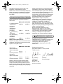
Konformitätserklärung
Wir erklären in alleiniger Verantwortung, dass die-
ses Produkt mit den folgenden Normen überein-
stimmt: EN 60745 gemäß den Bestimmungen der
Richtlinien 2006/42/EG, 2000/14/EG.
Technische Unterlagen bei:
Adolf Würth GmbH & Co. KG, Abt PFW
74650 Künzelsau
N. Heckmann A. Kräutle
Chairman of General Manager
Adolf Würth
GmbH & Co. KG
Künzelsau: 01.06.2010
BMH 40-XES MH 5-XES
L
PA
(Schalldruckpegel)
93 dB (A) 95 dB (A)
K
PA
(Schalldruckpegel-
Messungenauigkeit)
3 dB (A) 3 dB (A)
L
WA
(Schallleistung)
104 dB (A) 106 dB (A)
K
WA
(Schallleistung-
Messungenauigkeit)
3 dB (A) 3,6 dB (A)
BMH 40-XES MH 5-XES
Hammerbohren in Beton
Schwingungsemissions-
wert a
h
9,1 m/s
2
–
Unsicherheit K 1,6 m/s
2
–
Meißeln
Schwingungsemissions-
wert a
h
7,4 m/s
2
8,3 m/s
2
Unsicherheit K 1,6 m/s
2
1,5 m/s
2
Änderungen vorbehalten
0702 653 X.book Seite 9 Freitag, 9. Juli 2010 9:37 09

10
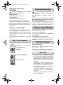
Machine Elements
1 Dust protection cap
2 Locking sleeve
3 Clamping band
4 Operating mode selector switch
5 Vibration damper
6 On/Off switch
7 Lock-on button for On/Off switch
8 Torque selector switch
9 Dial control for impact rate/speed preselection
10 Push-button for depth-stop adjustment
11 Auxiliary handle
12 Knurled nut for auxiliary handle
13 Depth stop
Not all of the accessories illustrated or described are included
as standard delivery.
Intended Use
BMH 40-XES: The machine is intended for hammer
drilling in concrete, brick and stone as well as for
chiselling.
MH 5-XES: The machine is intended for chiselling in
concrete, brick, stone and asphalt.
The user is responsible for damage caused by usage
other then intended.
Read all safety warnings and all
instructions. Failure to follow the
warnings and instructions may result in electric
shock, fire and/or serious injury.
Save all warnings and instructions for future ref-
erence.
Working safely with this machine is
possible only when the operating
and safety information are read
completely and the instructions
contained therein are strictly fol-
lowed. In addition, the general
safety instructions in the enclosed
booklet must be followed. Before
using for the first time, ask for a
practical demonstration.
❏ Wear ear protectors with impact drills. Expo-
sure to noise can cause hearing loss.
❏ Use auxiliary handles supplied with the tool.
Loss of control can cause personal injury.
❏ Hold power tool by insulated gripping sur-
faces, when performing an operation where
the cutting accessory may contact hidden wir-
ing or its own cord. Cutting accessory contact-
ing a “live” wire may make exposed metal
parts of the power tool “live” and could give the
operator an electric shock.
❏ Use suitable detectors to determine if utility
lines are hidden in the work area or call the
local utility company for assistance. Contact
with electric lines can lead to fire and electric
shock. Damaging a gas line can lead to explo-
sion. Penetrating a water line causes property
damage or may cause an electric shock.
❏ When working with the machine, always hold
it firmly with both hands and provide for a
secure stance. The power tool is guided more
secure with both hands.
❏ Secure the workpiece. A workpiece clamped
with clamping devices or in a vice is held more
secure than by hand.
❏ Keep your workplace clean. Blends of materi-
als are particularly dangerous. Dust from light
alloys can burn or explode.
❏ Always wait until the machine has come to a
complete stop before placing it down. The tool
insert can jam and lead to loss of control over
the power tool.
❏ Never use the machine with a damaged cable.
Do not touch the damaged cable and pull the
mains plug when the cable is damaged while
working. Damaged cables increase the risk of
an electric shock.
❏ Use only original Würth accessories.
WARNING
GB
☞
For further notes on safety refer to the enclosed sheet.
Hammer Safety Warnings
0702 653 X.book Seite 10 Freitag, 9. Juli 2010 9:37 09

11
Tool Specifications
Auxiliary Handle/Depth Stop
❏ Before any work on the machine itself, pull the
mains plug.
❏ Operate the machine only with the auxiliary
handle 11.
BMH 40-XES:
Loosen the auxiliary handle by turning the knurled
nut 12 anticlockwise.
The auxiliary handle 11 can be set to any position
for a secure and low-fatigue working posture.
The tensioning strap 3 of the auxiliary handle must
remain in the groove
Then, retighten the auxiliary handle by turning the
knurled nut 12 clockwise.
The drilling depth can be set with the depth stop 13.
For this, press the button for the depth-stop adjust-
ment 10, adjust the required drilling depth X and
release the button again.
The notched groove on depth stop 13 must face
downward
MH 5-XES:
The auxiliary handle 11 can be set to any position
for a secure and low-fatigue working posture.
Loosen the knurled nut 12, rotate the auxiliary han-
dle 7 around the axis of the machine to the required
position and tighten the knurled nut 12 again.
The auxiliary handle 11 can be mounted to a differ-
ent position. For this, completely unscrew the knurled
nut 12 and then pull out the hexagon bolt upward.
Pull off the auxiliary handle 11 to the side and turn
around the remaining clamping element by 180°.
Mount the auxiliary handle 11 in reverse order.
Changing the Tool
❏ Before any work on the machine itself, pull the
mains plug.
With the SDS-max tool holder, simpler and easier
tool changing is possible without additional aids.
The dust protection cap 1 largely prevents the entry
of drilling dust into the tool holder during operation.
When inserting the tool, take care that the dust pro-
tection cap 1 is not damaged.
❏ A damaged dust protection cap should be
changed immediately. We recommend having
this carried out by an after-sales service.
Inserting
Clean and lightly grease the shank end of the tool.
Insert the tool in a twisting manner into the tool
holder until it latches itself.
Check the latching by pulling the tool.
Removing
Push back the locking sleeve 2 and remove the tool.
Starting Operation
Switching On and Off
MH 5-XES:
To switch on the machine, push the On/Off
switch 6.
To switch off the machine, press the On/Off switch
6 again
BMH 40-XES:
To switch on the machine, push the On/Off
switch 6.
To lock on the On/Off switch 6, hold the pressed
switch and additionally slide the lock-on button 7
up. The lock-on function can only be used in chisel-
ling mode. When the lock-on function is activated in
drilling mode, the power tool automatically switches
off for safety reasons.
To switch off the machine, press the On/Off
switch 6 again
Rotary Hammer BMH 40-XES
Demolition Ham-
mer MH 5-XES
Article number 0702 553 X 0702 563 X
Impact energy
per stroke 1300 W 1300 W
Tool holder 2–12 J 2–12 J
Tool holder SDS-Max SDS-Max
Drilling capacity in
concrete
- Drill bit
- Core bit
12–45 mm
40–100 mm
–
–
Optimal drilling
capacity in concrete
- Drill bit 25–35 mm –
Chisel positions 18 18
Weight, approx 6.95 kg 6.2 kg
0702 653 X.book Seite 11 Freitag, 9. Juli 2010 9:37 09

12
Soft Starting
The soft starting function limits the speed when
switching on and then automatically increases the
speed, which, for example, prevents jerky starting
when inserting the drill bit into an existing hole.
Switching the Torque
(BMH 40-XES)
Actuate the torque selector switch 8 only
when the machine is stopped and when the
application tool is free.
Low torque:
Set the torque selector switch 8 to the upper position.
High torque:
Set the torque selector switch 8 to the bottom posi-
tion.
After a power failure, the torque selector switch
automatically resets to the „Low torque“ setting.
This function reduces the danger of injury, as most
applications are possible in the „Low torque“ setting.
Setting the Speed/Impact Rate
The electronic control enables variably adjustable
impact rate/speed preselection for jobs suitable for
the material being worked.
The constant electronic control keeps the preselected
impact rate/speed between operation with no-load
and load almost constant.
Select the impact rate/speed preselection with dial
control 9 according to the material.
Mode Selector Switch
❏ Operate the mode selector switch 4 only when
the machine is at a standstill.
Set the mode selector switch 4 to the required posi-
tion:
:
Drilling,Hammer drilling
(BMH 40-XES)
Changing the Chiselling Position
Chiselling (rotation off)
Safety Clutch
If the tool insert becomes caught or jammed,
the drive to the drill spindle is interrupted.
(Disengagement torque of the clutch: 40 Nm and
80 Nm)
Because of the forces that occur, always hold the
power tool firmly with both hands and provide for
a secure stance.
If the drilling tool jams, switch the machine off and
loosen the drilling tool. When switching the machine
on with the drilling tool jammed, high reaction tor-
ques can occur!
Changing the Chiselling Position
The chisel can be locked in 18 positions. In this man-
ner, the optimum working position can be set for
each application.
Insert the chisel in the tool holder.
Turn the mode selector switch 4 to “Changing the
chiselling position”.
Turn the tool holder to the desired chiselling position.
Allow the mode selector switch 4 to latch in the “Chisel-
ling” position. The tool holder is locked in this position.
Working Instruction
Vibration Damping
The integrated vibration damping feature reduces
occurring vibrations.
The soft grip handle increases the safety against slip-
ping off, and thus provides for a better grip and
handling of the power tool.
Dust Extraction
– Dusts from materials such as lead-containing
coatings, some wood types, minerals and metal
can be harmful to one’s health. Touching or
breathing-in the dusts can cause allergic reac-
tions and/or lead to respiratory infections of the
user or bystanders.
Certain dusts, such as oak or beech dust, are con-
sidered as carcinogenic, especially in connection
with wood-treatment additives (chromate, wood
preservative). Materials containing asbestos may
only be worked by specialists.
- Provide for good ventilation of the working place.
- It is recommended to wear a P2 filter-class res-
pirator.
Observe the relevant regulations in your country
for the materials to be worked.
0702 653 X.book Seite 12 Freitag, 9. Juli 2010 9:37 09

13
Maintenance and Cleaning
❏ Before any work on the machine itself, pull the
mains plug.
❏ For safe and proper working, always keep the
machine and the ventilation slots clean.
The power tool must be serviced by a Würth master
Service after 150 operating hours.
Service Indication
The yellow LED lights up when the carbon brushes
are almost completely worn. After approx. 8 further
operating hours, the brushes will be completely
worn and the motor will shut off automatically.
The red LED lights up when the lock-on button is used
in a different operating mode than chiselling. The
red LED starts to flash when a power tool malfunc-
tion is given, or when the brushes are completely
worn.
If the machine should fail despite the care taken in
manufacturing and testing, repair should be carried
out by a Würth Master-Service agent.
For all correspondence and spare parts orders,
always include the article number on the type plate
of the machine.
For the current spare parts list of this machine, log
into the Internet under
“http://www.wuerth.com/partsmanager” or ask
for a copy at your nearest Würth branch office.
Disposal
Power tools, accessories and packaging should be
sorted for environmental-friendly recycling.
Only for EC countries:
Do not dispose of power tools into
household waste!
According to the European Directive
2002/96/EC on waste electrical
and electronic equipment and its
incorporation into national law, power tools that are
no longer suitable for use must be separately col-
lected and sent for recovery in an environmen-
tal-friendly manner.
Warranty
For this Würth tool, we provide a warranty in
accordance with statutory/country-specific regula-
tions from the date of purchase (proof of purchase
by invoice or delivery note). Damage that has
occurred will be corrected by replacement or repair.
Damage caused by normal wear, overloading or
improper handling is excluded from the warranty.
Claims can be accepted only when the machine is
presented undisassembled to a Würth branch office,
your Würth sales representative or a customer serv-
ice agent for Würth pessure air and power tools.
Noise/Vibration Information
Measured values determined according to
2000/14/EG.
Wear hearing protection!
Overall vibrational value (vector sum of three direc-
tions) determined according to EN 60 745:
The vibration emission level given in this information
sheet has been measured in accordance with a
standardised test given in EN 60745 and may be
used to compare one tool with another. It may be
used for a preliminary assessment of the vibrational
impact.
The declared vibration emission level represents the
main applications of the power tool. However if the
power tool is used for other applications, with differ-
ent accessories or poorly maintained, the vibration
emission may differ. This may significantly increase
the vibrational impact over the total working period.
An estimation of the level of exposure to vibration
should also take into account the times when the tool
is switched off or when it is running but not actually
doing the job. This may significantly reduce the
exposure level over the total working period.
BMH 40-XES MH 5-XES
L
PA
(sound pressure
level
)
93 dB (A) 95 dB (A)
K
PA
(sound pressure level-
Measuring inaccuracy)
3 dB (A) 3 dB (A)
L
WA
(sound power level)
104 dB (A) 106 dB (A)
K
WA
(sound power level-
Measuring inaccuracy)
3 dB (A) 3.6 dB (A)
BMH 40-XES MH 5-XES
Hammer drilling in
concrete
Vibrational emission
value
a
h
9.1 m/s
2
–
uncertainty K 1.6 m/s
2
–
Chiselling
Vibrational emission
value
a
h
7.4 m/s
2
8.3 m/s
2
uncertainty K 1.6 m/s
2
1.5 m/s
2
0702 653 X.book Seite 13 Freitag, 9. Juli 2010 9:37 09

14
Identify additional safety measures to protect the
operator from the effects of vibration such as: Main-
tain the power tool and the accessories, keep the
hands warm, organisation of work patterns.
Declaration of Conformity
We declare under our sole responsibility that this
product is in conformity with the following standards
or standardization documents: EN 60745 accord-
ing to the provisions of the regulations
2006/42/EG, 2000/14/EG.
Technical file at:
Adolf Würth GmbH & Co. KG, Abt PFW
74650 Künzelsau
N. Heckmann A. Kräutle
Chairman of General Manager
Adolf Würth
GmbH & Co. KG
Künzelsau: 01.06.2010
Änderungen vorbehalten
0702 653 X.book Seite 14 Freitag, 9. Juli 2010 9:37 09

15
Elementi dell’apparecchio
1 Protezione antipolvere
2 Bussola di bloccaggio
3 Nastro tensore
4 Selettore modi operativi
5 Sistema antivibrazione
6 Interruttore di avvio/arresto
7 Pulsante di bloccaggio interruttore
avvio/arresto
8 Commutatore di coppia
9 Rotella di regolazione preselezione numero di
colpi/preselezione numero di giri
10 Pulsante per regolazione della battuta di
profondità
11 Impugnatura supplementare
12 Dado zigrinato per impugnatura
supplementare
13 Asta di profondità
L’accessorio illustrato o descritto nelle istruzioni per l’uso non
è compreso nella fornitura standard!
Leggere tutte le avvertenze
di pericolo e le istruzioni
operative. In caso di mancato rispetto delle avver-
tenze di pericolo e delle istruzioni operative si
potrà creare il pericolo di scosse elettriche, incendi
e/o incidenti gravi.
Conservare tutte le avvertenze di pericolo e le
istruzioni operative per ogni esigenza futura.
È possibile lavorare con la mac-
china senza incorrere in pericoli
soltanto dopo aver letto completa-
mente le istruzioni per l’uso e l’opu-
scolo avvertenze per la sicurezza e
seguendo rigorosamente le istru-
zioni in essi contenute. Attenersi
inoltre rigorosamente alle indica-
zioni di sicurezza generali che si
trovano nel manuale allegato.
Fatevi istruire praticamente prima
di passare all’operazione pratica.
❏ Impiegando trapani battenti usare la prote-
zione acustica. L’effetto del rumore può cau-
sare la perdita dell’udito.
❏ Utilizzare le impugnature supplementari for-
nite insieme all’apparecchio. La perdita del
controllo può comportare il pericolo di lesioni.
❏ Tenere l’apparecchio per le superfici isolate
dell’impugnatura qualora venissero effettuati
lavori durante i quali l’accessorio potrebbe
venire a contatto con cavi elettrici nascosti
oppure con il proprio cavo di rete. Il contatto
con un cavo sotto tensione può mettere sotto
tensione anche parti metalliche dell’apparec-
chio, causando una scossa elettrica.
❏ Al fine di rilevare linee di alimentazione
nascoste, utilizzare adatte apparecchiature di
ricerca oppure rivolgersi alla locale società
erogatrice. Un contatto con linee elettriche può
provocare lo sviluppo di incendi e di scosse
elettriche. Danneggiando linee del gas si può
creare il pericolo di esplosioni. Penetrando una
tubazione dell’acqua si provocano seri danni
materiali oppure vi è il pericolo di provocare
una scossa elettrica.
❏ Durante le operazioni di lavoro è necessario
tenere l’elettroutensile sempre con entrambe
le mani ed adottare una posizione di lavoro
sicura. Utilizzare con sicurezza l’elettroutensile
tenendolo sempre con entrambe le mani.
❏ Assicurare il pezzo in lavorazione. Un pezzo
in lavorazione può essere bloccato con sicu-
rezza in posizione solo utilizzando un apposito
dispositivo di serraggio oppure una morsa a
vite e non tenendolo con la semplice mano.
❏ Mantenere pulita la propria zona di lavoro.
Miscele di materiali di diverso tipo possono
risultare particolarmente pericolose. La pol-
vere di metalli leggeri può essere infiammabile
ed esplosiva.
❏ Prima di posare l’elettroutensile, attendere
sempre fino a quando si sarà fermato comple-
tamente. L’accessorio può incepparsi e com-
portare la perdita di controllo dell’elettrouten-
sile.
❏ Mai utilizzare l’elettroutensile con un cavo
danneggiato. Non toccare il cavo danneg-
giato ed estrarre la spina di rete in caso che si
dovesse danneggiare il cavo mentre si lavora.
Cavi danneggiati aumentano il rischio di una
scossa di corrente elettrica.
❏ Impiegare solo accessori originali Würth.
I
☞
Per altre istruzioni di sicurezza si veda il foglio allegato.
Indicazioni di sicurezza
per martelli
0702 653 X.book Seite 15 Freitag, 9. Juli 2010 9:37 09

16
Uso conforme alle norme
BMH 40-XES: La macchina è idonea per forature
battenti nel calcestruzzo, in mattoni ed in roccia
naturale e così pure per lavori di scalpellatura.
MH 5-XES: L’elettroutensile è ideale per lavori di
scalpellatura nel calcestruzzo, nella muratura, nella
roccia naturale e nell’asfalto.
Per danni provocati da uso non conforme alle
norme, risponde esclusivamente l’Utente.
Dati tecnici
Impugnatura supplementare/
asta di profondità
❏ Prima di qualunque intervento sull’elettrouten-
sile estrarre la spina di rete dalla presa.
❏ mpiegare la macchina soltanto con l’impugna-
tura supplementare 11.
BMH 40-XES:
Allentare l’impugnatura ruotando verso sinistra il
dado zigrinato 12.
L’impugnatura supplementare 11 può essere spo-
stata liberamente e regolata in modo da permettere
di prendere una posizione di lavoro di assoluta
maneggevolezza.
Durante questa operazione il nastro tensore 3
dell’impugnatura supplementare deve rimanere
nella scanalatura.
Serrare saldamente poi di nuovo l’impugnatura
ruotando verso destra il dado zigrinato 12.
Con l’asta di profondità 13, si può regolare la pro-
fondità di trapanatura.
A tal fine, premere il tasto per la regolazione della
battuta di profondità 10, regolare la richiesta pro-
fondità della foratura X e lasciare di nuovo il tasto.
La scanalatura sull’asta di profondità 13 deve
essere rivolta verso il basso.
MH 5-XES:
L’impugnatura supplementare 11 può essere spo-
stata liberamente e regolata in modo da permettere
di prendere una posizione di lavoro di assoluta
maneggevolezza.
Allentare il dado zigrinato 12, ribaltare l’impugna-
tura supplementare 11 attorno all’asse della mac-
china portandola alla posizione richiesta ed avvi-
tare di nuovo bene il dado zigrinato 12.
L’impugnatura supplementare 11 può essere mon-
tata in un’altra posizione. A tal fine, svitare comple-
tamente il dado zigrinato 12 ed estrarre quindi la
vite a testa esagonale completamente tirandola
verso l’alto. Tirare l’impugnatura supplementare 11
lateralmente e ribaltare di 180° il particolare di ser-
raggio rimanente. Montare l’impugnatura supple-
mentare 11 seguendo l’ordine inverso.
Cambio degli utensili
❏ Prima di qualunque intervento sull’elettrouten-
sile estrarre la spina di rete dalla presa.
Tramite il mandrino portautensile SDS-max è possi-
bile sostituire l’utensile accessorio in maniera sem-
plice e comoda senza dover ricorrere all’impiego di
ulteriori attrezzi.
La protezione antipolvere 1 ha la funzione di impe-
dire in larga misura che la polvere provocata
forando possa arrivare a penetrare nel mandrino
portautensile durante la fase di funzionamento.
Applicando l’accessorio, attenzione a non danneg-
giare la protezione antipolvere 1.
❏ Una protezione antipolvere danneggiata deve
essere sostituita immediatamente. Si consiglia di
affidare l’operazione ad un Centro di Assi-
stenza Clienti.
Martello perfora-
tore BMH 40-XES
Martello piccona-
tore MH 5-XES
Codice di
ordinazione 0702 553 X 0702 563 X
Potenza nominale
assorbita 1300 W 1300 W
Forza colpo singolo 2–12 J 2–12 J
Attacco utensile SDS-Max SDS-Max
Potenza di foratura
nel calcestruzzo
- Punta da trapano
piena
- Punta a corona
12–45 mm
40–100 mm
–
–
Ottimale potenza di
foratura nel calce-
struzzo
- Punta da trapano
piena 25–35 mm –
Regolazione scal-
pello 18 18
Peso, ca. 6,95 kg 6,2 kg
0702 653 X.book Seite 16 Freitag, 9. Juli 2010 9:37 09

17
Montaggio dell’utensile accessorio
Pulire il gambo dell’utensile accessorio ed applicarvi
un leggero strato di grasso.
Applicare l’accessorio nel mandrino portautensile
ruotandolo fino a farlo sarà arrivato a bloccarsi
autonomamente.
Controllare il bloccaggio tirando l’accessorio.
Smontaggio dell’utensile accessorio
Spingere il mandrino di serraggio 2 all’indietro ed
estrarre l’accessorio.
Messa in servizio
Avvio/arresto
MH 5-XES:
Per la messa in funzione dell’elettroutensile premere
l’interruttore di avvio/arresto 6.
Per lo spegnimento dell’elettroutensile premere di
nuovo l’interruttore di avvio/arresto 6.
BMH 40-XES:
Per la messa in funzione dell’elettroutensile premere
l’interruttore di avvio/arresto 6.
Per il bloccaggio dell’interruttore di avvio/arresto 6
tenerlo premuto e spingere inoltre il pulsante di bloc-
caggio 7. Il bloccaggio può essere utilizzato esclusi-
vamente nel funzionamento scalpellatura. Se il bloc-
caggio viene attivato nel funzionamento foratura,
l’elettroutensile si spegne automaticamente per
ragioni di sicurezza.
Per lo spegnimento dell’elettroutensile premere di
nuovo l’interruttore di avvio/arresto 6 successiva-
mente rilasciarlo.
Avviamento dolce
L’avviamento dolce limita il numero di giri durante
l’accensione e aumenta poi lo stesso automatica-
mente, questo impedisce p.es. un avviamento a
scatti durante l’inserimento della punta in un foro
esistente.
Commutazione della coppia
(BMH 40-XES)
Azionare il commutatore di coppia 8 esclusiva-
mente ad apparecchio spento e se l’accessorio
è libero.
Coppia bassa:
Regolare il commutatore di coppia 8 verso l’alto.
Coppia alta:
Regolare il commutatore di coppia 8 verso il basso.
Dopo un’interruzione di corrente, il commutatore di
coppia ritorna automaticamente sulla regolazione
«Coppia bassa».
Questa funzione riduce il pericolo di lesioni in
quanto la maggior parte dei lavori sono possibili
con la regolazione «Coppia bassa».
Regolazione del numero di giri/
numero di colpi
L’elettronica di regolazione consente una presele-
zione in continuo del numero di colpi/numero di giri
per lavori adatti al materiale.
L’elettronica costante mantiene quasi costante la
preselezione del numero di colpi/numero di giri
preselezionata tra il funzionamento al minimo ed il
funzionamento sotto carico.
Selezionare la preselezione del numero di
colpi/numero di giri con la rotella di regolazione 9
corrispondente al materiale.
Interruttore di arresto
rotazione-percussione
❏ L’interruttore di arresto rotazione-percussione 4
può essere azionato soltanto quando la mac-
china è ferma.
Mettere l’interruttore di arresto rotazione-percus-
sione 4 sulla posizione che si desidera:
Foratura/Foratura a martello
(BMH 40-XES)
Cambiare scalpellatura
Scalpellatura (arresto rotazione)
Frizione a stacco
La trasmissione all’alberino filettato si blocca
se l’utensile ad innesto si inceppa oppure
resta bloccato.
(Momento di disinnesto del giunto: 40 Nm e 80 Nm)
Per via delle rilevanti forze che si sviluppano men-
tre si opera in questo modo, afferrare sempre
l’elettroutensile con entrambe le mani ed assicu-
rarsi una sicura posizione operativa.
0702 653 X.book Seite 17 Freitag, 9. Juli 2010 9:37 09

18
In caso di blocco della punta utensile, disinserire la
macchina ed allentare la punta utensile. Avviando la
macchina con la punta utensile bloccata si provo-
cano alti momenti di reazione!
Cambiare scalpellatura
Lo scalpello può essere impostato su 18 diverse posi-
zioni di arresto. In questo modo è possibile determi-
nare con facilità la posizione di lavoro migliore.
Applicare lo scalpello nel portautensili.
Ruotare l’interruttore arresto rotazione-percus-
sione 4 alla posizione «Cambiare scalpellatura».
Ruotare il portautensili nella posizione di scalpella-
tura che si desidera.
Lasciar innestare in posizione l’interruttore arresto
rotazione-percussione 4 «Scalpellare». In questa
posizione il portautensili è bloccato.
Istruzioni per il lavoro
Sistema antivibrazione
Il sistema antivibrazione integrato riduce le vibra-
zioni che si formano.
L’impugnatura morbida aumenta la sicurezza con-
tro il pericolo di scivolamento e permette quindi una
migliore maneggevolezza dell’elettroutensile.
Aspirazione polvere
– Polveri e materiali come vernici contenenti
piombo, alcuni tipi di legname, minerali e metalli
possono essere dannosi per la salute. Il contatto
oppure l’inalazione delle polveri possono cau-
sare reazioni allergiche e/o malattie delle vie
respiratorie dell’operatore oppure delle persone
che si trovano nelle vicinanze.
Determinate polveri come polvere da legname di
faggio o di quercia sono considerate cancero-
gene, in modo particolare insieme ad additivi per
il trattamento del legname (cromato, protezione
per legno). Materiale contenente amianto deve
essere lavorato esclusivamente da personale spe-
cializzato.
- Provvedere per una buona aerazione del posto-
di lavoro.
- Si consiglia di portare una mascherina protet-
tiva con classe di filtraggio P2.
Osservare le norme in vigore nel Vostro paese
per i materiali da lavorare.
Cura e manutenzione
❏ Prima di qualunque intervento sull’elettrouten-
sile estrarre la spina di rete dalla presa.
❏ Per poter garantire buone e sicure operazioni di
lavoro, tenere sempre pulite la macchina e le fes-
sure di ventilazione.
Dopo 150 ore l’elettroutensile deve essere sottopo-
sto a manutenzione da parte del Würth master-Ser-
vice.
Indicazione Service
Il LED giallo è illuminato se le spazzole di carbone
sono quasi consumate. Dopo ulteriori 8 ore d’eser-
cizio le spazzole sono completamente usurate ed il
motore viene disinserito automaticamente.
Il LED rosso è illuminato se il pulsante di bloccaggio
viene utilizzato in un modo operativo diverso dalla
scalpellatura. Il LED rosso inizia a lampeggiare in
caso di presenza di un guasto all’elettroutensile
oppure se le spazzole sono completamente usurate.
Se nonostante gli accurati procedimenti di produ-
zione e di controllo la macchina dovesse guastarsi,
la riparazione va fatta effettuare da un punto di
assistenza Würth master-Service autorizzato.
Per ogni tipo di richiesta o di ordinazione di pezzi
di ricambio, è indispensabile comunicare sempre il
codice articolo riportato sulla targhetta di fabbrica-
zione della macchina.
L’attuale distinta dei pezzi di ricambio di questa
macchina può essere consultata nel sito Internet
«http://www.wuerth.com/partsmanager» oppure
è possibile richiederla presso la più vicina filiale
Würth.
Smaltimento
Avviare ad un riciclaggio rispettoso dell’ambiente
gli imballaggi, gli elettroutensili e gli accessori
dismessi.
Solo per i Paesi della CE:
Non gettare elettroutensili dismessi
tra i rifiuti domestici!
Conformemente alla norma della
direttiva CE 2002/96 sui rifiuti di
apparecchiature elettriche ed elet-
troniche (RAEE) ed all’attuazione del recepimento
nel diritto nazionale, gli elettroutensili diventati
inservibili devono essere raccolti separatamente ed
essere inviati ad una riutilizzazione ecologica.
0702 653 X.book Seite 18 Freitag, 9. Juli 2010 9:37 09

19
Garanzia legale
Per questo prodotto Würth, la garanzia è conforme
alle disposizioni di legge vigenti nei singoli Paesi, a
partire dalla data di acquisto (faranno fede la fat-
tura o la bolla di consegna). I difetti subentrati ven-
gono eliminati attraverso una fornitura di ricambio
oppure provvedendo alle dovute riparazioni.
Si esclude ogni prestazione di garanzia in caso di
danni dovuti a normale usura, a sovraccarico,
oppure a trattamento ed impiego inappropriato.
Informazioni sulla rumorosità e
sulla vibrazione
Valori misurati conformemente alla norma
2000/14/EG.
Usare auricolari di protezione!
Valori totali delle oscillazioni (somma dei vettori in
tre direzioni) misurati conformemente alla norma
EN 60 745:
Il livello di oscillazione indicato nelle presenti istru-
zioni è stato rilevato seguendo una procedura di
misurazione conforme alla norma EN 60745 e può
essere utilizzato per il confronto di elettroutensili. Lo
stesso è idoneo anche per una valutazione provviso-
ria del carico da oscillazioni.
Il livello di oscillazione indicato rappresenta gli
impieghi principali dell’elettroutensile. Se tuttavia
l’elettroutensile viene utilizzato per altri impieghi
con accessori differenti oppure con manutenzione
insufficiente, il livello di oscillazione può differire.
Questo può aumentare sensibilmente il carico da
oscillazioni per l’intero periodo operativo.
Per una valutazione precisa del carico da oscilla-
zioni sarebbe necessario considerare anche i tempi
in cui l’apparecchio è spento oppure è acceso ma
non viene utilizzato effettivamente. Questo può
ridurre chiaramente il carico da oscillazioni per
l’intero periodo operativo.
Adottare misure di sicurezza supplementari per la
protezione dell’operatore dall’azione delle oscilla-
zioni, come p. es.: manutenzione di elettroutensile e
accessori, tenere calde le mani, organizzazione dei
cicli di lavorazione.
Dichiarazione di
conformità
Assumendone la piena responsabilità, dichiariamo
che il prodotto è conforme alle seguenti normative
ed ai relativi documenti: EN 60745 in base alle pre-
scrizioni delle direttive 2006/42/EG,
2000/14/EG.
Facicolo tecnico presso:
Adolf Würth GmbH & Co. KG, Abt PFW
74650 Künzelsau
N. Heckmann A. Kräutle
Chairman of General Manager
Adolf Würth
GmbH & Co. KG
Künzelsau: 01.06.2010
BMH 40-XES MH 5-XES
L
PA
(solitamente di pres-
sione acustica) 93 dB (A) 95 dB (A)
K
PA
(solitamente di pres-
sione acustica-Preci-
sione di misura) 3 dB (A) 3 dB (A)
L
WA
(livello della poten-
za sonora) 104 dB (A) 106 dB (A)
K
WA
(livello della
potenza sonora-
Precisione di misura) 3 dB (A) 3,6 dB (A)
BMH 40-XES MH 5-XES
Foratura a martello nel
calcestruzzo
Valore di emissione
dell’oscillazione a
h
9,1 m/s
2
–
Incertezza della misura K 1,6 m/s
2
–
Scalpellatura
Valore di emissione
dell’oscillazione a
h
7,4 m/s
2
8,3 m/s
2
Incertezza della misura K 1,6 m/s
2
1,5 m/s
2
Con riserva di modifiche
0702 653 X.book Seite 19 Freitag, 9. Juli 2010 9:37 09

20
Eléments de l’appareil
1 Capuchon anti-poussière
2 Douille de verrouillage
3 Bande de serrage
4 Commutateur du mode de service
5 Dispositif d’amortissement des vibrations
6 Interrupteur Marche/Arrêt
7 Bouton de blocage interrupteur Marche/Arrêt
8 Commutateur du couple
9 Molette de présélection de la vitesse/fréquence
de frappe
10 Bouton de réglage de la butée de profondeur
11 Poignée supplémentaire
12 Ecrou moletée pour poignée supplémentaire
13 Butée de profondeur
Les accessoires reproduits ou décrits ne sont pas forcément
fournis avec la machine.
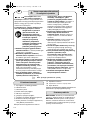
Lire tous les avertisse-
ments de sécurité et toutes
les instructions. Ne pas suivre les avertissements et
instructions peut donner lieu à un choc électrique,
un incendie et/ou une blessure sérieuse.
Conserver tous les avertissements et toutes les ins-
tructions pour pouvoir s’y reporter ultérieurement.
Pour travailler sans risque avec cet
appareil, lire intégralement au
préalable les instructions d’utilisa-
tion et les remarques concernant la
sécurité. Respecter scrupuleuse-
ment les indications et les consi-
gnes qui y sont données. En plus, il
convient de respecter les consignes
d’ordre général touchant à la sécu-
rité qui sont définies dans le cahier
ci-joint. Avant la première mise en
service, laisser quelqu’un connais-
sant bien cet appareil vous indi-
quer la façon de s’en servir.
❏ Portez une protection acoustique lors du per-
çage à percussion. Une forte exposition au
bruit peut provoquer une perte d’audition.
❏ Utilisez les poignées supplémentaires fournies
avec l’appareil. Le fait de perdre le contrôle de
l’appareil peut entraîner de blessures.
❏ Tenir l’outil par les surfaces de préhension iso-
lées, lors de la réalisation d’une opération au
cours de laquelle l’organe de coupe peut
entrer en contact avec un câblage non appa-
rent ou son propre cordon d’alimentation. Le
contact avec un fil « sous tension » peut égale-
ment mettre « sous tension » les parties métalli-
ques exposées de l’outil électrique et provoquer
un choc électrique sur l’opérateur.
❏ Utiliser des détecteurs appropriés afin de
déceler des conduites cachées ou consulter les
entreprises d’approvisionnement locales. Un
contact avec des lignes électriques peut provo-
quer un incendie ou un choc électrique. Un
endommagement d’une conduite de gaz peut
provoquer une explosion. La perforation d’une
conduite d’eau provoque des dégâts matériels
et peut provoquer un choc électrique.
❏ Toujours bien tenir l’outil électroportatif des
deux mains et veiller à toujours garder une
position de travail stable. Avec les deux mains,
l’outil électroportatif est guidé de manière plus
sûre.
❏ Bloquer la pièce à travailler. Une pièce à tra-
vailler serrée par des dispositifs de serrage ou
dans un étau est fixée de manière plus sûre que
tenue dans les mains.
❏ Tenir propre la place de travail. Les mélanges
de matériaux sont particulièrement dange-
reux. Les poussières de métaux légers peuvent
être explosives ou inflammables.
❏ Avant de déposer l’outil électroportatif, atten-
dre que celui-ci soit complètement à l’arrêt.
L’outil risque de se coincer, ce qui entraîne une
perte de contrôle de l’outil électroportatif.
❏ Ne jamais utiliser un outil électroportatif dont
le câble est endommagé. Ne pas toucher à un
câble endommagé et retirer la fiche du câble
d’alimentation de la prise du courant, au cas
où le câble serait endommagé lors du travail.
Un câble endommagé augmente le risque d’un
choc électrique.
❏ N’utiliser que des accessoires d’origine
Würth.
WARNUNGAVERTISSEMENT
F
☞
D’autres consignes de sécurité figurent sur la feuille ci-jointe.
Avertissements de sécurité
pour les marteaux
0702 653 X.book Seite 20 Freitag, 9. Juli 2010 9:37 09
Pagina se încarcă...
Pagina se încarcă...
Pagina se încarcă...
Pagina se încarcă...
Pagina se încarcă...
Pagina se încarcă...
Pagina se încarcă...
Pagina se încarcă...
Pagina se încarcă...
Pagina se încarcă...
Pagina se încarcă...
Pagina se încarcă...
Pagina se încarcă...
Pagina se încarcă...
Pagina se încarcă...
Pagina se încarcă...
Pagina se încarcă...
Pagina se încarcă...
Pagina se încarcă...
Pagina se încarcă...
Pagina se încarcă...
Pagina se încarcă...
Pagina se încarcă...
Pagina se încarcă...
Pagina se încarcă...
Pagina se încarcă...
Pagina se încarcă...
Pagina se încarcă...
Pagina se încarcă...
Pagina se încarcă...
Pagina se încarcă...
Pagina se încarcă...
Pagina se încarcă...
Pagina se încarcă...
Pagina se încarcă...
Pagina se încarcă...
Pagina se încarcă...
Pagina se încarcă...
Pagina se încarcă...
Pagina se încarcă...
Pagina se încarcă...
Pagina se încarcă...
Pagina se încarcă...
Pagina se încarcă...
Pagina se încarcă...
Pagina se încarcă...
Pagina se încarcă...
Pagina se încarcă...
Pagina se încarcă...
Pagina se încarcă...
Pagina se încarcă...
Pagina se încarcă...
Pagina se încarcă...
Pagina se încarcă...
Pagina se încarcă...
Pagina se încarcă...
Pagina se încarcă...
Pagina se încarcă...
Pagina se încarcă...
Pagina se încarcă...
Pagina se încarcă...
Pagina se încarcă...
Pagina se încarcă...
Pagina se încarcă...
Pagina se încarcă...
Pagina se încarcă...
Pagina se încarcă...
Pagina se încarcă...
Pagina se încarcă...
Pagina se încarcă...
Pagina se încarcă...
Pagina se încarcă...
Pagina se încarcă...
Pagina se încarcă...
Pagina se încarcă...
Pagina se încarcă...
Pagina se încarcă...
Pagina se încarcă...
Pagina se încarcă...
Pagina se încarcă...
Pagina se încarcă...
Pagina se încarcă...
Pagina se încarcă...
Pagina se încarcă...
Pagina se încarcă...
Pagina se încarcă...
Pagina se încarcă...
Pagina se încarcă...
Pagina se încarcă...
Pagina se încarcă...
Pagina se încarcă...
Pagina se încarcă...
Pagina se încarcă...
Pagina se încarcă...
Pagina se încarcă...
Pagina se încarcă...
Pagina se încarcă...
Pagina se încarcă...
Pagina se încarcă...
Pagina se încarcă...
Pagina se încarcă...
Pagina se încarcă...
Pagina se încarcă...
Pagina se încarcă...
Pagina se încarcă...
Pagina se încarcă...
Pagina se încarcă...
Pagina se încarcă...
Pagina se încarcă...
-
 1
1
-
 2
2
-
 3
3
-
 4
4
-
 5
5
-
 6
6
-
 7
7
-
 8
8
-
 9
9
-
 10
10
-
 11
11
-
 12
12
-
 13
13
-
 14
14
-
 15
15
-
 16
16
-
 17
17
-
 18
18
-
 19
19
-
 20
20
-
 21
21
-
 22
22
-
 23
23
-
 24
24
-
 25
25
-
 26
26
-
 27
27
-
 28
28
-
 29
29
-
 30
30
-
 31
31
-
 32
32
-
 33
33
-
 34
34
-
 35
35
-
 36
36
-
 37
37
-
 38
38
-
 39
39
-
 40
40
-
 41
41
-
 42
42
-
 43
43
-
 44
44
-
 45
45
-
 46
46
-
 47
47
-
 48
48
-
 49
49
-
 50
50
-
 51
51
-
 52
52
-
 53
53
-
 54
54
-
 55
55
-
 56
56
-
 57
57
-
 58
58
-
 59
59
-
 60
60
-
 61
61
-
 62
62
-
 63
63
-
 64
64
-
 65
65
-
 66
66
-
 67
67
-
 68
68
-
 69
69
-
 70
70
-
 71
71
-
 72
72
-
 73
73
-
 74
74
-
 75
75
-
 76
76
-
 77
77
-
 78
78
-
 79
79
-
 80
80
-
 81
81
-
 82
82
-
 83
83
-
 84
84
-
 85
85
-
 86
86
-
 87
87
-
 88
88
-
 89
89
-
 90
90
-
 91
91
-
 92
92
-
 93
93
-
 94
94
-
 95
95
-
 96
96
-
 97
97
-
 98
98
-
 99
99
-
 100
100
-
 101
101
-
 102
102
-
 103
103
-
 104
104
-
 105
105
-
 106
106
-
 107
107
-
 108
108
-
 109
109
-
 110
110
-
 111
111
-
 112
112
-
 113
113
-
 114
114
-
 115
115
-
 116
116
-
 117
117
-
 118
118
-
 119
119
-
 120
120
-
 121
121
-
 122
122
-
 123
123
-
 124
124
-
 125
125
-
 126
126
-
 127
127
-
 128
128
-
 129
129


Master BMH 40-XES Translation Of The Original Instructions
- Categorie
- Ciocane rotative
- Tip
- Translation Of The Original Instructions
- Acest manual este potrivit și pentru
în alte limbi
- italiano: Master BMH 40-XES
Alte documente
-
Würth EB 13-2 Original Instructions Manual
-
-
Kress 1100 BMH MAX Manualul proprietarului
-
-
Bosch GBH 4-32 DFR Instrucțiuni de utilizare
-
Bosch GBH 4-32 DFR Specificație
-
-
-
Parkside 277023 Original Instructions Manual
-
Bosch GBH 3-28 DFR Specificație