HOTPOINT/ARISTON BHWD 125 EU Manualul utilizatorului
- Categorie
- Mașini de spălat
- Tip
- Manualul utilizatorului

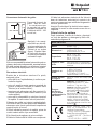
GB
1
English,1
! This symbol reminds you to read this
booklet.
Contents
Installation, 2-3-4-5
Unpacking and levelling
Connecting the electricity and water supplies
The first wash cycle
Technical data
Instructions for the fitter
Care and maintenance, 6
Cutting off the water or electricity supply
Cleaning the washer-dryer
Cleaning the detergent dispenser drawer
Caring for the door and drum of your appliance
Cleaning the pump
Checking the water inlet hose
Precautions and tips, 7
General safety
Disposal
Description of the washer-dryer and
starting a wash cycle, 8-9
Control panel
Indicator lights
Starting a wash cycle
Wash cycles, 10
Table of wash cycles
Personalisation, 11
Setting the temperature
Setting the drying cycle
Functions
Detergents and laundry, 12
Detergent dispenser drawer
Bleach cycle
Preparing the laundry
Garments requiring special care
Load balancing system
Troubleshooting, 13
Service, 14
GB
BHWD 125
Instructions for use
WASHER DRYER
BG
RO
SR
Română,15
Български,29
српски,43

2
GB
Installation
! This instruction manual should be kept in a safe
place for future reference. If the washer dryer is
sold, transferred or moved, make sure that the
instruction manual remains with the machine so
that the new owner is able to familiarise himself/
herself with its operation and features.
! Read these instructions carefully: they contain
vital information relating to the safe installation
and operation of the appliance.
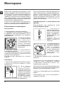
Unpacking and levelling
Unpacking
1. Remove the washer dryer from its packaging.
2. Make sure that the washer dryer has not been
damaged during the transportation process. If it
has been damaged, contact the retailer and do not
proceed any further with the installation process.
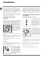
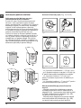
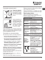
3. Remove the 4 pro-
tective screws (used
during transportation)
and the rubber washer
with the corresponding
spacer, located on the
rear part of the applian-
ce (see figure).
4. Close off the holes using the plastic plugs
provided.
5. Keep all the parts in a safe place: you will
need them again if the washer dryer needs to
be moved to another location.
! Packaging materials should not be used as
toys for children.
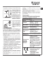
Levelling
1. Install the washer dryer on a flat sturdy floor,
without resting it up against walls, furniture ca-
binets or anything else.
2. If the floor is not per-
fectly level, compensa-
te for any unevenness
by tightening or loo-
sening the adjustable
front feet (see figure);
the angle of inclination,
measured in relation to
the worktop, must not
exceed 2°.
Levelling the machine correctly will provide it with
stability, help to avoid vibrations and excessive
noise and prevent it from shifting while it is ope-
rating. If it is placed on carpet or a rug, adjust
the feet in such a way as to allow a sufficient
ventilation space underneath the washer dryer.
Connecting the electricity and wa-
ter supplies
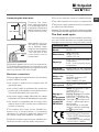
Connecting the water inlet hose
1. Connect the supply
pipe by screwing it to
a cold water tab using
a ¾ gas threaded con-
nection (see figure).
Before performing the
connection, allow the
water to run freely until
it is perfectly clear.
2. Connect the inlet
hose to the washer dr-
yer by screwing it onto
the corresponding wa-
ter inlet of the applian-
ce, which is situated on
the top right-hand side
of the rear part of the
appliance (see figure).
3. Make sure that the hose is not folded over
or bent.
! The water pressure at the tap must fall within
the values indicated in the Technical details table
(see next page).
! If the inlet hose is not long enough, contact a
specialised shop or an authorised technician.
! Never use second-hand hoses.
! Use the ones supplied with the machine.

GB
3
65 - 100 cm
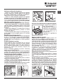
Connecting the drain hose
Connect the drain
hose, without bending
it, to a drainage duct or
a wall drain located at a
height between 65 and
100 cm from the floor;
alternatively, rest it on
the side of a washba-
sin or bathtub, faste-
ning the duct supplied
to the tap (see figure).
The free end of the
hose should not be
underwater.
! We advise against the use of hose extensions;
if it is absolutely necessary, the extension must
have the same diameter as the original hose and
must not exceed 150 cm in length.
Electrical connections
Before plugging the appliance into the electricity
socket, make sure that:
•the socket is earthed and complies with all
applicable laws;
•thesocketisabletowithstandthemaximum
power load of the appliance as indicated in the
Technical data table (see opposite);
•thepowersupplyvoltagefallswithinthevalues
indicated in the Technical data table (see opposite);
•thesocketiscompatiblewiththeplugofthe
washer dryer. If this is not the case, replace the
socket or the plug.
! The washer dryer must not be installed ou-
tdoors, even in covered areas. It is extremely
dangerous to leave the appliance exposed to
rain, storms and other weather conditions.
! When the washer dryer has been installed, the
electricity socket must be within easy reach.
! Do not use extension cords or multiple sockets.
! The cable should not be bent or compressed.
! The power supply cable must only be replaced
by authorised technicians.
Warning! The company shall not be held responsible
in the event that these regulations are not respected.
The first wash cycle
Once the appliance has been installed, and before
you use it for the first time, run a wash cycle with
detergent and no laundry, using the wash cycle 2.
Technical data
Model
BHWD 125
Dimensions
width 59,5 cm
height 81,5 cm
depth 54,5 cm
Capacity
from 1 to 7 kg for the wash
programme
from 1 to 5 kg for the drying
programme
Electrical
connections
please refer to the technical
data plate fixed to the machine
Water con-
nections
maximum pressure 1 MPa
(10 bar)
minimum pressure 0.05
MPa (0.5 bar)
drum capacity 52 litres
Spin speed
up to 1200 rotations per
minute
Energy ra-
ted
programmes
according to
regulation
EN 50229
Wash: programme 3; tem-
perature 60°C;
using a load of 7 kg.
Drying: Drying: the smaller
load must be dried by se-
lecting the dryness level.
The load must consist of 2
sheets, 1 pillowcase and 1
hand towel;
the remainder of the load
must be dried by selecting
the dryness level.
This appliance conforms to
the following EC Directives:
- 2004/108/EC (Electromagne-
tic Compatibility)
- 2006/95/EC (Low Voltage)
- 2012/19/EU - WEEE

4
GB
A
B
C
D
E
Tur seite
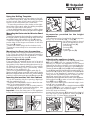
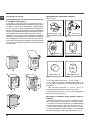
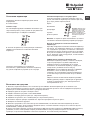
Instructions for the fitter
Mounting the wooden panel onto the door
and inserting the machine into cabinets:
In the case where the machine must be shipped
for final installation after the wooden panel has
been mounted, we suggest leaving it in its ori-
ginal packaging. The packaging was designed
to make it possible to mount the wooden panel
onto the machine without removing it completely
(see figures below).
The wooden panel that covers the face of
the machine must not be less than 18 mm in
thickness and can be hinged on either the right
or left. For the sake of practicality when using
the machine, we recommend that the panel be
hinged on the same side as the door for the
machine itself - the left.
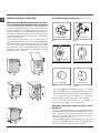
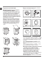
Door Mounting Accessories (Fig. 1-2-3-4-5).
Fig. 1
N° 2 Hinges
N° 1 Magnet N° 1 Magnet plate
N° 1 Rubber plug
N° 2 Hinge Supports
N° 4 Spacers
Fig. 2
Fig. 3 Fig. 4
Fig. 5
Fig. 4/B
- No. 6 type A self-threading screws, l =13 mm.
- No. 2 type B metric, countersunk screws, l =25;
for fastening the magnet plate to the cabinet.
- No. 4 type C metric screws, l =15 mm; for
mounting the hinge supports to the cabinet.
- No. 4 type D metric screws, l =7 mm; for
mounting the hinges on the supports.
Mounting the Parts onto the Face of the
Machine.
- Fit the hinge supports to the appliance front
panel, positioning the hole marked with an arrow
in fig. 1 so that it is on the inner side of the front
panel. Fit a spacer (fig. 4/B) between the surfa-
ces using type C screws.
- Fit the magnet plate at the top of the opposite
side, using type B screws to fix two spacers (fig.
4/B) between the plate and the surface.

GB
5
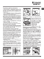
Using the Drilling Template.
- To trace the positions of the holes on the left-
hand side of the panel, align the drilling template
to the top left side of the panel using the lines
traced on the extremities as a reference.
- To trace the positions of the holes on the right-
hand side of the panel, align the drilling template
to the top right side of the panel.
- Use an appropriately sized router to mill the holes
for the two hinges, the rubber plug and the magnet.
Mounding the Parts onto the Wooden Panel
(Door).
- Insert the hinges into the holes (the movable part of
the hinge must be positioned facing away from the
panel) and fasten them with the 4 type A screws.
- Insert the magnet into the top hole on the op-
posite side of the hinges and fasten it with the
two type B screws.
- Insert the rubber plug into the bottom hole.
The panel is now ready to be mounted onto the
machine.
Mounting the Panel into the machine.
Insert the nib of the hinge (indicated by the arrow
in fig. 2) into the hole for the hinge and push the
panel towards the front of the machine. Fasten
the two hinges with the type D screws.
Fastening the plinth guide.
If the machine is installed at the end of a set of
modular cabinets, mount either one or both of
the guides for the base molding (as shown in fig.
8). Adjust them for depth based on the position
of the base molding, and, if necessary, fasten
the base to the guides (fig. 9).
This is how to assemble the plinth guide (fig. 8):
Fasten angle P using screw R, insert plinth guide
Q into the special slot and once it is in the desired
position, lock it in place using angle P and screw R.
Inserting the machine into the Cabinet.
- Push the machine into the opening, aligning it
with the cabinets (fig. 6).
- Regulate the adjustable feet to raise the ma-
chine to the appropriate height.
- To adjust the position of the wooden panel in
both the vertical and horizontal directions, use
the C and D screws, as shown in fig. 7.
Important: close the lower part of the appliance
front by ensuring that the plinth rests against the floor.
Fig. 8 Fig. 9
Accessories provided for the height
adjustment.
The following can be found inside the polystyrene
lid (fig. 10): 2 crossbars (G), 1 strip (M)
the following can be found
inside the appliance drum:
4 additional feet (H),
4 screws (I),
4 screws (R),
4 nuts (L),
2 plinth guides (Q)
Adjusting the appliance height.
The height of the appliance can be adjusted (from
815 mm to 835 mm), by turning the 4 feet.
Should you require the appliance to be placed
higher than the above height, you need to use the
following accessories to raise it to up to 870 mm:
The two crossbars (G); the 4 feet (H); the 4 screws (I); the
4 nuts (L) then perform the following operations (fig. 11):
remove the 4 original feet, place a crossbar G at
the front of the appliance, fastening it in place
using screws I (screwing them in where the ori-
ginal feet were) then insert the new feet H.
Repeat the same operation at the back of the appliance.
Now adjust feet H to raise or lower the appliance
from 835 mm to 870 mm.
Once you have reached the desired height, lock
nuts L onto crossbar G.
To adjust the appliance to a height between 870
mm and 900 mm, you need to mount strip M,
adjusting feet H to the required height.
Insert the strip as follows:
loosen the three screws N situated at the front of
the Top cover of the appliance, insert strip M as
shown in fig. 12, then fasten screws N.
D
C
C
570
min
815
540
595
820 ÷ 900
600 min
Fig. 6 Fig. 7
L
I
H
G
M
Fig. 11 Fig. 12
Fig. 10

6
GB
Care and maintenance
Cutting off the water and electri-
city supplies
•Turnoffthewatertapaftereverywashcycle.
This will limit wear on the hydraulic system
inside the washer dryer and help to prevent
leaks.
•Unplugthewasherdryerwhencleaningit
and during all maintenance work.
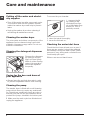
Cleaning the washer dryer
The outer parts and rubber components of the
appliance can be cleaned using a soft cloth
soaked in lukewarm soapy water. Do not use
solvents or abrasives.
Cleaning the detergent dispenser
drawer
Remove the dispenser
by raising it and pul-
ling it out (see figure).
Wash it under running
water; this operation
should be repeated
frequently.
Caring for the door and drum of
your appliance
•Alwaysleavetheportholedoorajarinorder
to prevent unpleasant odours from forming.
Cleaning the pump
The washer dryer is fitted with a self-cleaning
pump which does not require any maintenan-
ce. Sometimes, small items (such as coins or
buttons) may fall into the pre-chamber which
protects the pump, situated in its bottom part.
! Make sure the wash cycle has finished and
unplug the appliance.
1
2
To access the pre-chamber:
1. unscrew the lid
by rotating it anti-
clockwise (see figu-
re): a little water may
trickle out. This is
perfectly normal;
2. clean the inside thoroughly;
3. screw the lid back on;
Checking the water inlet hose
Check the inlet hose at least once a year. If
there are any cracks, it should be replaced
immediately: during the wash cycles, water
pressure is very strong and a cracked hose
could easily split open.
! Never use second-hand hoses.

GB
7
Precautions and tips
! This washer dryer was designed and constructed in ac-
cordance with international safety regulations. The following
information is provided for safety reasons and must therefore
be read carefully.
General safety
• This appliance was designed for domestic use only.
•Thisappliancecanbeusedbychildrenaged
from 8 years and above and persons with
reduced physical, sensory or mental capabi-
lities or lack of experience and knowledge if
they have been given supervision or instruction
concerning use of the appliance in a safe way
and understand the hazards involved. Children
shall not play with the appliance. Cleaning and
user maintenance shall not be made by children
without supervision.
– Do not dry unwashed items in the tumble dryer.
– Items that have been soiled with substan-
ces such as cooking oil, acetone, alcohol,
petrol, kerosene, spot removers, turpentine,
waxes and wax removers should be washed
in hot water with an extra amount of deter-
gent before being dried in the tumble dryer.
– Items such as foam rubber (latex foam),
shower caps, waterproof textiles, rubber
backed articles and clothes or pillows fitted
with foam rubber pads should not be dried in
the tumble dryer.
– Fabric softeners, or similar products,
should be used as specified by the fabric
softener instructions.
– The final part of a tumble dryer cycle occurs
without heat (cool down cycle) to ensure that
the items are left at a temperature that ensures
that the items will not be damaged.
WARNING: Never stop a tumble dryer before
the end of the drying cycle unless all items
are quickly removed and spread out so that
the heat is dissipated.
•Do not touch the machine when barefoot or with wet or
damp hands or feet.
•Do not pull on the power supply cable when unplugging
the appliance from the electricity socket. Hold the plug
and pull.
•Do not open the detergent dispenser drawer while the
machine is in operation.
•Do not touch the drained water as it may reach extreme-
ly high temperatures.
•Never force the porthole door. This could damage the
safety lock mechanism designed to prevent accidental
opening.
•If the appliance breaks down, do not under any circum-
stances access the internal mechanisms in an attempt
to repair it yourself.
•Always keep children well away from the appliance while
it is operating.
•The door can become quite hot during the wash cycle.
•If the appliance has to be moved, work in a group of two
or three people and handle it with the utmost care. Never
try to do this alone, because the appliance is very heavy.
•Before loading laundry into the washer-dryer, make sure
the drum is empty.
• During the drying phase, the door tends to get quite hot.
• Donotusetheappliancetodryclothesthat
have been washed with flammable solvents
(e.g. trichlorethylene).
• Donotusetheappliancetodryfoamrubber
or similar elastomers.
• Make sure that the water tap is turned on during
the drying cycles.
• Childrenoflessthan3yearsshouldbekept
away from the appliance unless continuou-
sly supervised.
• Removeallobjectsfrompocketssuchas
lighters and matches.
Disposal
• Disposingofthepackagingmaterials:observelocalregu-
lations so that the packaging may be re-used.
• The EuropeanDirective 2012/19/EU - WEEEon Waste
Electrical and Electronic Equipment, requires that old hou-
sehold electrical appliances must not be disposed of in the
normal unsorted municipal waste stream. Old appliances
must be collected separately in order to optimise the recovery
and recycling of the materials they contain and reduce the
impact on human health and the environment. The crossed
out “wheeled bin” symbol on the product reminds you of
your obligation, that when you dispose of the appliance it
must be separately collected. Consumers should contact
their local authority or retailer for information concerning the
correct disposal of their old appliance.

8
GB
Detergent dispenser drawer: used to dispense
detergents and washing additives (see “Detergents and
laundry”).
ON/OFF button: switches the washer-dryer on and off.
WASH CYCLE knob: programmes the wash cycles. Du-
ring the wash cycle, the knob does not move.
FUNCTION buttons with indicator light: used to select the
available functions. The indicator light corresponding to the
selected function will remain lit.
TEMPERATURE knob: sets the temperature or the cold
wash cycle (see “Personalisation”).
DRYING knob: used to set the desired drying programme
(see “Personalisation”).
WASH CYCLE PROGRESS/DELAY TIMER
indicator
light
s: used to monitor the progress of the wash cycle.
The illuminated indicator light shows which phase is in
progress.
If the Delay Timer function has been set, the time remai-
ning until the wash cycle starts will be indicated (see next
page).
DOOR LOCKED indicator light: indicates whether the
door may be opened or not (see next page).
START/PAUSE button with indicator light: starts or tem-
porarily interrupts the wash cycles.
N.B. To pause the wash cycle in progress, press this
button; the corresponding indicator light will flash orange,
while the indicator light for the current wash cycle phase
will remain lit in a fixed manner. If the DOOR LOCKED
indicator light is switched off, the door may be opened
(wait approximately 3 minutes).
To start the wash cycle from the point at which it was inter-
rupted, press this button again.
Standby mode
This washing machine, in compliance with new energy sa-
ving regulations, is fitted with an automatic standby system
which is enabled after about 30 minutes if no activity is
detected. Press the ON-OFF button briefly and wait for the
machine to start up again.
Consumption in off-mode: 0,5 W
Consumption in Left-on: 8 W
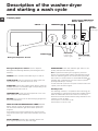
Description of the washer-dryer
and starting a wash cycle
TEMPERATURE
knob
Detergent dispenser drawer
WASH CYCLE PROGRESS/
DELAY TIMER indicator lights
FUNCTION
buttons with
indicator lights
ON/OFF
button
DRYING
knob
DOOR
LOCKED
indicator light
START/PAUSE
button with indicator
light
Control panel
WASH CYCLE
knob

GB
9
Indicator lights
The indicator lights provide important information.
This is what they can tell you:
Delayed start
If the DELAY TIMER function has been activated (see “Per-
sonalisation”), after the wash cycle has been started the
indicator light corresponding to the selected delay period
will begin to flash:
As time passes, the remaining delay will be displayed and
the corresponding indicator light will flash:
Once the set delay has elapsed, the flashing indicator light
will switch off and the selected wash cycle will begin.
Wash cycle phase indicator lights
Once the desired wash cycle has been selected and has be-
gun, the indicator lights switch on one by one to indicate which
phase of the cycle is currently in progress.
Note: during the “Drain” phase, the indicator light corre-
sponding to the “Spin” cycle phase will illuminate.
Function buttons and corresponding indicator lights
When a function is selected, the corresponding indicator
light will illuminate.
If the selected function is not compatible with the program-
med wash cycle, the corresponding indicator light will flash
and the function will not be activated.
If a function which is incompatible with another function
selected previously, only the most recent selection will
remain active.
Door locked indicator light
If this indicator light is on, the appliance door is locked to
prevent it from being opened accidentally; to avoid any
damage, wait for the indicator light to switch off before you
open the appliance door (wait approximately 3 minutes).
N.B. If the DELAY TIMER function is activated, the door
cannot be opened; pause the machine by pressing the
START/PAUSE button if you wish to open it.
! If the START/PAUSE indicator light (orange) flashes
rapidly at the same time as the function indicator light, this
indicates a problem has occurred (see “Troubleshooting”).
Starting a wash cycle
1. Turn the washing machine on by pressing the ON/OFF button. All the indicator lights will turn on for a few seconds, then
only the indicator lights relative to the selected programme settings will remain lit and the START/PAUSE indicator light will
flash.
2. Load the laundry and close the door.
3. Set the WASH CYCLE knob to the desired programme.
4. Set the washing temperature (see “Personalisation”).
5. Set the drying cycle if necessary (see “Personalisation”).
6. Measure out the detergent and washing additives (see “Detergents and laundry”).
7. Select the desired functions.
8. Start the wash cycle by pressing the START/PAUSE button and the corresponding indicator light will remain lit in a fixed
manner, in green. To cancel the set wash cycle, pause the machine by pressing the START/PAUSE button and select a new
cycle.
9. At the end of the wash cycle the indicator light will switch on. The DOOR LOCKED indicator light will switch off, indi-
cating that the door may be opened (wait approximately 3 minutes). Take out your laundry and leave the appliance door ajar
to make sure the drum dries completely. Switch the washer-dryer off by pressing the ON/OFF button.
Wash
Rinse
Spin
Dry
End of wash cycle
DOOR
LOCKED
indicator light
Note: as soon as a drying level
or time period has been set,
this indicator light illuminates
to indicate that the selected
wash cycle will be followed by a
drying phase.

10
GB
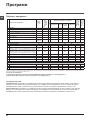
Wash cycles
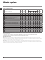
Table of wash cycles
Specials wash cycles
Mix 15’(wash cycle 8) this wash cycle was designed to wash lightly soiled garments quickly: it lasts just 15 minutes and
therefore saves both energy and time. By selecting this wash cycle (8 at 30°C), it is possible to wash different fabrics together
(except for wool and silk items), with a maximum load of 1.5 kg.
Daily 30’(wash cycle 9) this wash cycle was designed to wash lightly soiled garments quickly: it lasts just 30 minutes and
therefore saves both energy and time. By selecting this wash cycle (9 at 30°C), it is possible to wash different fabrics together
(except for wool and silk items), with a maximum load of 3 kg.
For all Test Institutes:
1) Test wash cycle in compliance with regulation EN 50229: set wash cycle 3 with a temperature of 60°C.
2) Long wash cycle for cottons: set wash cycle 3 with a temperature of 40°C.
Wash cycles
Description of the wash cycle
Max.
temp.
(°C)
Max.
speed
(rpm)
Drying
Detergents
Max.
load
(kg)
Cycle
dura-
tion
Prewash Bleach Wash
Fabric
softener
Essentials
1
Cotton Prewash: extremely soiled whites. 90° 1200
-
7 170’
2
Cotton: Heavily soiled whites and resistant colours. 60° 1200
-
7 140’
3
Eco Cotton 60° (1): heavily soiled whites and resistant colours. 60° 1200
- -
7 180’
3
Eco Cotton 40° (2): lightly soiled whites and delicate colours. 40° 1200
- -
7 170’
4
Coloureds: Lightly soiled whites and delicate colours. 40° 1200
-
7 90’
5
Synthetics: lightly soiled resistant colours.
40°
(Max 60°)
1000
-
3 100’
Specials
6 Delicates
30° 0
- -
1 80’
7
Wool: For wool, cashmere, etc. 40° 800
- -
1,5 70’
8
Mix 15': To refresh lightly soiled garments quickly (not suitable
for wool, silk and clothes which require washing by hand).
30° 800 - - -
1,5 15’
9
Daily 30':To refresh lightly soiled garments quickly (not suitable
for wool, silk and clothes which require washing by hand).
30° 800 - - -
3 30’
10 Wash&Dry 45’
30° 1200
- -
1 45’
Drying
11
Drying Cottons - -
- - - - 5 -
12
Drying Synthetics - -
- - - - 3 -
13
Drying Wool - -
- - - - 1,5 -
Partials wash cycles
A
Rinse - 1200
- - -
7 36’
B
Spin - 1200
- - - - 7 10’
C
Pump Out - 0 - - - - - 7 3’
The length of cycle shown on the display or in this booklet is an estimation only and is calculated assuming standard working conditions. The actual duration can vary accor-
ding to factors such as water temperature and pressure, the amount of detergent used, the amount and type of load inserted, load balancing and any wash options selected.

GB
11
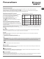
Setting the temperature
Turn the TEMPERATURE knob to set the wash temperature (see Table of wash cycles).
The temperature may be lowered, or even set to a cold wash ( ).
The washer-dryer will automatically prevent you from selecting a temperature which is higher than the maximum value set for
each wash cycle.
! Exception: if the 5 programme is selected, the temperature can be increased up to a value of 60°C.
Setting the drying cycle
Turn the DRYING knob to set the desired drying type.
Two options are available:
A - Based on time: from 40 to 180 minutes.
B - Based on the how damp the clothes are once they have
been dried:
Iron : slightly damp clothes, easy to iron.
Hanger : dry clothes to put away.
Cupboard : very dry clothes, recommended for towelling
and bathrobes.
If your laundry load to be washed and dried is much greater
than the maximum stated load (see adjacent table), perform
the wash cycle, and when the cycle is complete, divide the
garments into groups and put some of them back in the
drum. At this point, follow the instructions provided for a
“Drying only” cycle. Repeat this procedure for the remainder of the load.
N.B: When the drying is complete there is a cooling period, even though the DRYING knob is in the position.
Drying only
Turn the WASH CYCLE knob to one of the drying settings (11-12-13) according to the type of fabric, then select the desired
drying duration using the DRYING knob.
Functions
The various wash functions available with this washer-dryer will help to achieve the desired results, every time.
To activate the functions:
1. Press the button corresponding to the desired function;
2. the function is enabled when the corresponding indicator light is illuminated.
Note:
- If the selected function is not compatible with the programmed wash cycle, the corresponding indicator light will flash and
the function will not be activated.
- If a function which is incompatible with another function selected previously, only the most recent selection will remain active.
1/2
By selecting this function, reduces the spin speed.
Super Wash
Because a greater quantity of water is used in the initial phase of the cycle, and because of the increased cycle duration, this
function offers a high-performance wash.
Extra rinse
By selecting this function, the efficiency of the rinse is increased and optimal detergent removal is guaranteed. It is particularly
useful for sensitive skin.
Delay timer
This timer delays the start time of the wash cycle by up to 9 hours.
Press the button repeatedly until the indicator light corresponding to the desired delay time switches on. The fifth time the button
is pressed, the function will be disabled.
N.B. Once you have pressed the START/PAUSE button, the delay time may only be decreased if you wish to modify it.
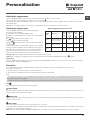
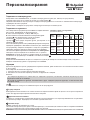
Personalisation
Table of Drying times (guideline values)
Fabric
type
Load type
Max.
load
(kg)
Cupboard
dry
Henger
dry
Iron
dry
Cotton
Clothing of different
sizes, Terry towels
5 250 210 190
Syn-
thetics
Sheets, Shirts, Py-
jamas, socks, etc.
3 180 130 115
Wool
Knitwear, Pullovers,
etc.
1,5 150 140 130

12
GB
Detergents and laundry
Preparing the laundry
•Dividethelaundryaccordingto:
- the type of fabric/the symbol on the label
- the colours: separate coloured garments from whites.
•Emptyallgarmentpocketsandcheckthebuttons.
• Donotexceedthelistedvalues,whichrefertothe
weight of the laundry when dry: see “Table of wash
cycles”.
How much does your laundry weigh?
1 sheet 400-500 g
1 pillow case 150-200 g
1 tablecloth 400-500 g
1 bathrobe 900-1200 g
1 towel 150-250 g
Garments requiring special care
Delicates: use programme 6 to wash very delicate
garments. It is advisable to turn the garments inside out
before washing them. For best results, use liquid detergent
on delicate garments.
When selecting an exclusively time-based drying function, a
drying cycle is performed at the end of the wash cycle that is
particularly delicate, thanks to light handling and appropriate
temperature control of the water jet.
The recommended durations are:
1 kg of synthetic garments --> 150 min
1 kg of synthetic and cotton garments --> 180 min
1 kg of cotton garments --> 180 min
The degree of dryness depends on the load and fabric
composition.
Wool - Woolmark Apparel Care - Green:
the wool wash cycle of this machine has been approved
by The Woolmark Company for the washing of wool gar-
ments labelled as “hand wash” provided that the products
are washed according to the instructions on the garment
label and those issued by the manufacturer of this washing
machine (M1126)
Wash&Dry 45’ select programme
10
for washing and drying
lightly soiled garments (Cotton and Synthetic) in a short time.
This cycle may be used to wash and dry a laundry load of
up to 1 kg in just 45 minutes. To achieve optimum results,
use liquid detergent and pre-treat cuffs, collars and stains.
Load balancing system
Before every spin cycle, to avoid excessive vibrations and
to distribute the load in a uniform manner, the drum rotates
continuously at a speed which is slightly greater than the
washing rotation speed. If, after several attempts, the load is
not balanced correctly, the machine spins at a reduced spin
speed. If the load is excessively unbalanced, the washer-
dryer performs the distribution process instead of spinning.
To encourage improved load distribution and balance, we
recommend small and large garments are mixed in the load.
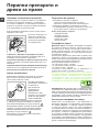
Detergent dispenser drawer
Good washing results also depend on the correct dose of
detergent: adding too much detergent will not necessa-
rily result in a more efficient wash, and may in fact cause
build up on the inside of your appliance and contribute to
environmental pollution.
!Use powder detergent for white cotton garments, for pre-
washing, and for washing at temperatures over 60°C.
!Follow the instructions given on the detergent packaging.
! Do not use hand washing detergents because these
create too much foam.
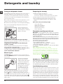
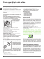
Open the detergent di-
spenser drawer and pour
in the detergent or washing
additive, as follows.
compartment 1: Pre-wash detergent (powder)
Before pouring in the detergent, make sure that extra com-
partment 4 has been removed.
compartment 2: Detergent for the wash cycle
(powder or liquid)
Liquid detergent should only be poured in immediately
prior to the start of the wash cycle.
compartment 3: Additives (fabric softeners, etc.)
The fabric softener should not overflow the grid.
extra compartment 4: Bleach
Bleach cycle
! Traditional bleach should be used on sturdy white fa-
brics, and delicate bleach for coloured fabrics, synthetics
and for wool.
This option is particularly
useful for the removal of
stubborn stains. Place extra
compartment 4 (supplied)
into compartment 1.
When pouring in the bleach,
be careful not to exceed
the “max” level marked
on the central pivot (see
figure). To run the bleach
cycle on its own, pour the bleach into extra compartment
4, set the “Rinse” programme and activate the “Super
Wash” option. To bleach during a wash cycle, pour in
the detergent and any fabric softener you wish to use, set
the desired wash cycle and enable the “Super Wash”
option. The use of extra compartment 4 excludes the “Pre-
wash” option.
M
AX
1
2
4
3
MAX
MAX

GB
13
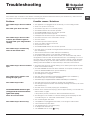
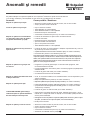
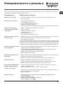
Troubleshooting
Your washer-dryer could fail to work. Before contacting the Technical Assistance Centre (see “Assistance”), make sure that
the problem cannot be not solved easily using the following list.
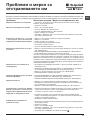
Problem:
The washer-dryer does not switch
on.
The wash cycle does not start.
The washer-dryer does not take
in water (the indicator light for
the first wash cycle stage flashes
rapidly).
The washer-dryer continuously
takes in and drains water.
The washer-dryer does not drain or
spin.
The washer-dryer vibrates a lot
during the spin cycle.
The washer-dryer leaks.
The START/PAUSE indicator light
(orange) and the function indicator
lights flash rapidly.
There is too much foam.
The washer-dryer does not dry.
Possible causes / Solutions:
• Theapplianceisnotpluggedintothesocketfully,orisnotmakingcontact.
• Thereisnopowerinthehouse.
• Thewasher-dryerdoorisnotclosedproperly.
• TheON/OFFbuttonhasnotbeenpressed.
• TheSTART/PAUSEbuttonhasnotbeenpressed.
• Thewatertaphasnotbeenopened.
• Adelayedstarthasbeenset(see “Personalisation”).
• Thewaterinlethoseisnotconnectedtothetap.
• Thehoseisbent.
• Thewatertaphasnotbeenopened.
• Thereisnowatersupplyinthehouse.
• Thepressureistoolow.
• TheSTART/PAUSEbuttonhasnotbeenpressed.
• Thedrainhoseisnotfittedataheightbetween65and100cmfromthefloor
(see “Installation”).
• Thefreeendofthehoseisunderwater(see “Installation”).
• Thewalldrainagesystemisnotfittedwithabreatherpipe.
If the problem persists even after these checks, turn off the water tap, switch
the appliance off and contact the Assistance Service. If the dwelling is on one of
the upper floors of a building, there may be problems relating to water drainage,
causing the washer-dryer to fill with water and drain continuously. Special anti-
draining valves are available in shops and help to avoid this inconvenience.
• Thewashcycledoesnotincludedraining:somewashcyclesrequirethedrain
phase to be started manually.
• TheANTI-CREASEfunctionhasbeenactivated:Tocompletethewashcycle,
press the START/PAUSE button (“Personalisation”).
• Thedrainhoseisbent(see “Installation”).
• Thedrainageductisclogged.
• Thedrumwasnotunlockedcorrectlyduringinstallation(see “Installation”).
• Thewasher-dryerisnotlevel(see “Installation”).
• Thewasher-dryeristrappedbetweencabinetsandwalls(see “Installation”).
• Thewaterinlethoseisnotscrewedonproperly(see “Installation”).
• Thedetergentdispenserdrawerisblocked(forcleaninginstructions,see “Care
and maintenance”).
• Thedrainhoseisnotfixedproperly(see “Installation”).
• Switchoffthemachineandunplugit,waitforapproximately1minuteandthen
switch it back on again.
If the problem persists, contact the Technical Assistance Service.
• Thedetergentisnotsuitableformachinewashing(itshoulddisplaythetext
“for washer-dryers” or “hand and machine wash”, or the like).
• Toomuchdetergentwasused.
• Theapplianceisnotpluggedintothesocket,ornotenoughtomakecontact.
• Therehasbeenapowerfailure.
• The appliance door is not shut properly.
• Adelayedstarthasbeenset.
• TheDRYINGknobisonthe setting.

14
GB
Service
Before calling for Assistance:
• Check whether you can solve the problem alone (see “Troubleshooting”);
• Restarttheprogrammetocheckwhethertheproblemhasbeensolved;
• Ifthisisnotthecase,contactanauthorisedTechnicalAssistanceCentreusingthetelephonenumberprovidedonthe
guarantee certificate.
! Always request the assistance of authorised technicians.
Have the following information to hand:
• thetypeofproblem;
• theappliancemodel(Mod.);
• theserialnumber(S/N).
This information can be found on the data plate applied to the rear of the washer-dryer, and can also be found on the front of
the appliance by opening the door.

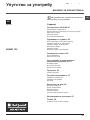
15
RO
Română
Sumar
Instalare, 16-17-18-19
Despachetare şi punere la nivel
Racorduri hidraulice şi electrice
Primul ciclu de spălare
Date tehnice
Instrucţiuni pentru instalator
Întreţinere şi curăţare, 20
Întreruperea alimentării cu apă şi curent electric
Curăţarea maşinii de spălat
Curăţarea compartimentului pentru detergent
Îngrijirea uşii şi a tamburului
Curăţarea pompei
Controlarea furtunului de alimentare cu apă
Precauţii şi sfaturi, 21
Norme de protecţie şi siguranţă generale
Aruncarea reziduurilor
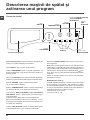
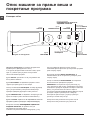
Descrierea maşinii de spălat şi activarea unui
program, 22-23
Panoul de control
Indicatoare luminoase
Activarea unui program
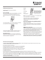
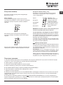
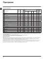
Programe, 24
Tabel de programe
Personalizare, 25
Reglarea temperaturii
Alegerea programului de uscare
Funcţii
Detergenţi şi rufe albe, 26
Compartimentul pentru detergenţi
Ciclu de albire
Pregătirea rufelor
Articole delicate
Sistemul de echilibrare a încărcăturii
Anomalii şi remedii, 27
Asistenţă, 28
RO
BHWD 125
Instrucţiuni de folosire
MAŞINĂ DE SPĂLAT ŞI USCAT
! Acest simbol îti aminteste sa citesti acest
manual de instructiuni.

16
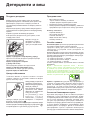
RO
Instalare
! Este important să păstraţi acest manual pen-
tru a-l putea consulta în orice moment. În caz
de vânzare, de cesiune sau de schimbare a
locuinţei, acesta trebuie să rămână împreună
cu maşina de spălat pentru a informa noul pro-
prietar cu privire la funcţionare şi la respectivele
avertismente.
! Citiţi cu atenţie instrucţiunile: veţi găsi
informaţii importante cu privire la instalare, la
folosire şi la siguranţă.
Despachetare şi punere la nivel
Despachetare
1. Scoaterea din ambalaj a maşinii de spălat.
2. Controlaţi ca maşina de spălat să nu fost
deteriorată în timpul transportului. Dacă este
deteriorată nu o conectaţi şi luaţi legătura cu
vânzătorul.
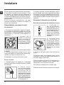
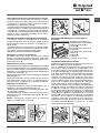
3. Scoateţi cele 4
şuruburi de protecţie
pentru transport şi
cauciucul cu respec-
tivul distanţier, situate
în partea posterioară
(a se vedea gura).
4. Închideţi oriciile cu dopurile din plastic aate
în dotare.
5. Păstraţi toate piesele: pentru cazul în care
maşina de spălat va trebui să e transportată,
piesele vor trebui montante din nou.
! Ambalajele nu sunt jucării pentru copii!
Punere la nivel
1. Instalaţi maşina de spălat pe o suprafaţă
plană şi rigidă, fără a o sprijini de ziduri, mobilă
sau altceva.
2 . D a c ă p o d e -
aua nu este perfect
orizontală, compensaţi
n e r e g u l a r i t ă ţ i l e
d e ş u r u b â n d s a u
înşurubând picioruşele
anterioare (a se vedea
gura); unghiul de încli-
nare, măsurat pe pla-
nul de lucru, nu trebuie
să depăşească 2°.
O nivelare precisă conferă stabilitate maşinii
şi evită vibraţii, zgomote şi deplasări pe timpul
funcţionării. În cazul mochetelor sau a unui co-
vor, reglaţi picioruşele astfel încât să menţineţi
sub maşina de spălat un spaţiu sucient pentru
ventilare.
Racorduri hidraulice şi electrice
Racordarea furtunului de alimentare cu apă
1 . Co n e c t a ţ i tu -
bul de alimentare,
înşurubându-l la un
robinet de apă rece cu
gura letată de 3/4 gaz
(a se vedea gura).
Înainte de conectare,
lăsaţi apa să curgă
până când nu a devine
limpede.
2. Conectaţi tubul
de alimentare la
maşina de spălat,
înşurubându-l la sur-
sa de apă respectivă,
amplasată în partea
posterioară, sus în
dreapta (a se vedea
gura).
3. Fiţi atenţi ca furtunul să nu e nici pliat nici
îndoit.
! Presiunea apei de la robinet trebuie să e
cuprinsă în valorile din tabelul Date tehnice (a
se vedea pagina alăturată).
! Dacă lungimea furtunului de alimentare nu
este sucientă, adresaţi-vă unui magazin spe-
cializat sau unui instalator autorizat.
! Nu folosiţi niciodată tuburi folosite deja.
! Utilizaţi tuburile furnizate împreună cu maşina.

17
RO
65 - 100 cm
Conectarea furtunului de golire
Conectaţi furtunul de
golire - fără a-l îndoi
- la canalizare sau
la racordul de golire
prevăzut pe perete, la
o înălţime de 65 - 100
cm de sol;
Sprijiniţi-l de margi-
nea căzii sau chiuve-
tei şi racordaţi şina de
ghidare din dotare la
robinet (a se vedea
gura). Capătul liber
al furtunului de golire
nu trebuie să rămână
cufundat în apă.
! Nu se recomandă folosirea furtunurilor prelun-
gitoare; dacă este indispensabil, acestea trebuie
să aibă acelaşi diametru ca şi furtunul original
şi nu trebuie să depăşească 150 cm lungime.
Racordarea electrică
Înainte de a introduce stecherul în priză,
asiguraţi-vă ca:
• priza să e cu împământare şi conform pre-
vederilor legale;
• priza să poată suporta sarcina maximă de
putere a maşinii, indicată în tabelul Date
Tehnice (a se vedea alături);
• tensiunea de alimentare să e cuprinsă în
valorile indicate în tabelul Date Tehnice (a se
vedea alături);
• priza să e compatibilă cu stecherul maşinii
de spălat. În caz contrar înlocuiţi stecherul.
! Maşina de spălat nu trebuie instalată afară,
nici chiar în cazul în care spaţiul este adăpostit,
deoarece este foarte periculoasă expunerea
maşinii la ploi şi furtuni.
! După instalarea maşinii de spălat, priza de
curent trebuie să e uşor accesibilă.
! Nu folosiţi prelungitoare şi prize multiple.
! Cablul nu trebuie să e îndoit sau comprimat.
! Cablul de alimentare trebuie să e înlocuit
doar de tehnicieni autorizaţi ai centrului de
service ce apare scris pe certicatul de garantie
emis de producator.
Atenţie! Producătorul îşi declină orice respon-
sabilitate în cazul în care aceste norme nu se
respectă.
Primul ciclu de spălare
După instalare, înainte de folosire, efectuaţi
un ciclu de spălare cu detergent şi fără rufe,
selectând programul 2.
Date tehnice
Model BHWD 125
Dimensiuni
lãrgime 59,5 cm
înãlþime 81,5 cm
profunzime 54,5 cm
Capacitate
de la 1 la 7 kg
pentru spãlare
de la 1 la 5 kg
pentru uscare
Legãturi elec-
trice
Vezi placuta cu caracteri-
sticile tehnice, aplicata pe
masina.
Legãturi hi-
drice
presiune maximã
1 MPa (10 bari)
presiune minimã
0,05 MPa (0,5 bari)
capacitatea cuvei 52 litri
Viteza de cen-
trifugare
pânã la 1200 de rotaþii pe
minut
Progra-
me de con-
trol pe baza
reglementările
EN 50229
spãlare: programul 3
temperatura 60°C; efec-
tuatã cu 7 kg de rufe.
uscare: uscarea cantităţii
mai mici (2kg) trebuie
efectuată selectând nivelul
de uscare “ ”, cantitatea
de lenjerie trebuie să se
compună din 2 cearceafuri,
1 feţe de pernă şi 1 pro-
soape; uscarea cantităţii
rămase trebuie să se facă
prin selectarea nivelului de
uscare “ ”.
Acest aparat este con-
form cu urmãtoarele Di-
rective Comunitare:
- 2004/108/CE (Compatibi-
litate Electromagneticã)
- 2006/95/CE (Tensiuni
Joase)
- 2012/19/EU - WEEE

18
RO
Instrucţiuni pentru instalator
Aplicarea panoului de lemn pe uşă şi
introducerea maşinii în mobilier:
În cazul în care, după montarea panoului
de lemn, este necesară livrarea maşinii
pentru montajul nal, vă sfătuim să o lăsaţi în
ambalajul original. În acest scop, ambalajul
original a fost realizat pentru a permite
montarea panoului de lemn pe maşină fără a
necesară scoatere completă din ambalaj a
maşinii (consultaţi gurile de mai jos).
Panoul de lemn ce acoperă partea frontală
nu trebuie să aibă o grosime mai mică de 18
mm şi poate prins cu balamale pe partea
dreaptă sau pe partea stângă. Din motive
de utilizare practică a maşinii, vă sfătuim ca
uşa să aibă acelaşi sens de deschidere ca şi
balamaua aplicată pe partea stângă.
A
B
C
D
E
Tur seite
Accesorii de montaj uşiţă (Fig. 1-2-3-4-5).
Fig. 1
Nr. 2 Balama
Nr. 1 Magnet Nr. 1 Placă magnet
Nr. 1 Diblu de cauciuc
Nr. 2 Suporturi balama
Nr. 4 Distanţiere
Fig. 2
Fig. 3 Fig. 4
Fig. 5
Fig. 4/B
- nr. 6 şuruburi autoletante l = 13 mm „tip A”.
- nr. 2 şuruburi metrice cu cap plat l = 25 mm „tip
B” pentru xarea plăcii magnetului pe mobilier.
- nr. 4 şuruburi metrice l = 15 mm „tip C”
pentru montarea suporturilor de balama pe
mobilier.
- nr. 4 şuruburi metrice l = 7 mm „tip D” pentru
montarea balamalelor pe suporturi.
Montarea detaliilor pe partea frontală a
maşinii.
- Montaţi suporturile de balama pe partea
frontală poziţionând oriciul indicat printr-o
săgeată în g. 1 spre partea interioară a părţii
frontală interpunând un distanţier (g. 4/B),
cu ajutorul unui şurub de tip C.
- Montaţi placa magnetului pe partea opusă
sus interpunând două distanţiere (g. 4/B),
cu ajutorul celor două şuruburi de tip B.

19
RO
Utilizarea şablonului de găurire.
- Pentru a trasa poziţiile găurilor pe partea
stângă a panoului, aliniaţi şablonul de găurire
pe latura superioară şi stânga a panoului,
respectând liniile trasate pe extremităţi.
- Pentru a trasa poziţiile găurilor pe partea
dreapta a panoului, aliniaţi şablonul de găurire
pe latura superioară şi dreapta a panoului.
- Cu o freză de dimensiuni adecvate realizaţi
cele patru locaşuri pentru cele două balamale,
diblul de cauciuc şi magnetul.
Montarea detaliilor pe panoul de lemn (Antina).
- Introduceţi balamalele în locaşurile pregătite
(partea mobilă a balamalei trebuie să e pusă
spre exteriorul panoului) şi xaţi-le cu 4 şuruburi
de tipul A.
- Introduceţi magnetul în locaşul de sus de pe
partea opusă a balamalei şi xaţi-l cu două
şuruburi de tipul B.
- Introduceţi diblul de cauciuc în locaşul de jos.
Acum, panoul este pregătit pentru a montat
pe maşină.
Montarea panoului pe maşină.
Introduceţi cârligul balamalei, indicat de săgeată
în fig. 2, în locaşul suportului balamalei,
împingeţi panoul spre partea frontală a maşinii
şi xaţi cele două balamale cu două şuruburi
de tipul D.
Fixarea ghidajului soclului.
Dacă maşina este instalată într-un colţ al
mobilierului modular, montaţi unul sau ambele
ghidaje ale soclului, aşa cum este indicat în
g. 8, reglând adâncimea în funcţie de poziţia
soclului şi, dacă este necesar, fixaţi-le de
acestea (g. 9).
Pentru montarea ghidajului soclului, efectuaţi
după cum urmează (g. 8):
Fixaţi colierul P cu şuruburile R, introduceţi ghidajul
soclului Q în oriciul opus şi o dată poziţionat în
punctul dorit blocaţi-l pe colierul P cu şuruburile R.
Introducerea maşinii în mobilier.
- Împingeţi aparatul în deschidere, aliniindu-l cu
celelalte piese de mobilier (g. 6).
- Utilizaţi picioruşele de reglare pentru a aduce
maşina la înălţimea dorită.
- Pentru a regla poziţia panoului de lemn pe
verticală şi pe orizontală, utilizaţi şuruburile C şi
D după cum este indicat în g. 7.
Important: închideţi partea de jos a părţii frontale
cu ajutorul soclului prin baterea de podea.
Fig. 8 Fig. 9
Accesorii din dotare pentru reglarea înălţimii.
În capacul de polistiren
(g. 10) se găsesc:
2 traverse (G); 1 tijă (M) în
interiorul cuvei se găsesc:
4 picioruşe suplimentare
(H); 4 şuruburi (I); 4
şuruburi (R);
4 piuliţe (L); 2 ghidaje de
soclu (Q).
Reglarea înălţimii maşinii.
Maşina poate reglată în înălţime (de la 815
mm la 835 mm) reglând cele 4 picioruşe.
Dacă se doreşte o înălţime mai mare decât cea
indicată mai sus, ce poate ajunge până la 870
mm, trebuie să utilizaţi accesoriile următoare:
Cele 2 traverse (G); cele 4 picioruşe (H); cele 4
şuruburi (I); cele 4 piuliţe (L), procedând după
cum urmează (g. 11):
Scoateţi cele 4 picioruşe iniţiale, poziţionaţi
o traversă G pe partea anterioară a maşinii,
fixaţi-o cu şuruburile I (înşurubându-le în
oriciile unde erau montate picioruşele iniţiale),
apoi introduceţi noile picioruşe H.
Repetaţi procedura de mai sus şi pentru partea
posterioară a maşinii.
În acest punct, reglând picioruşele H, maşina
poate reglată pe înălţime de la 835 mm la 870
mm.
În momentul în care s-a atins înălţimea dorită,
blocaţi piuliţele L pe traversa G.
Pentru a regla maşina pe înălţime între 870 mm
şi 900 mm trebuie să montaţi tija M, reglând
picioruşele H până la înălţimea dorită. Pentru
a introduce tija, procedaţi după cum urmează:
slăbiţi cele trei şuruburi N din partea anterioară
a capacului Top, introduceţi tija M după cum
se indică în g. 12, apoi blocaţi şuruburile N.
D
C
C
570
min
815
540
595
820 ÷ 900
600 min
Fig. 6 Fig. 7
L
I
H
G
M
Fig. 11 Fig. 12
Fig. 10

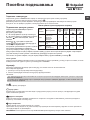
20
RO
Întreţinere şi curăţare
Întreruperea alimentării cu apă şi cu-
rent electric
• Închideţi robinetul de apă după fiecare
spălare. Se limitează astfel uzura instalaţiei
hidraulice a maşinii de spălat şi se elimină
pericolul scurgerilor.
• Scoateţi stecherul din priza de curent atunci
când curăţaţi maşina de spălat şi când se
efectuează lucrări de întreţinere.
Curăţarea maşinii de spălat
Partea externă şi părţile din cauciuc pot
curăţate cu o lavetă înmuiată în apă călduţă
şi săpun. Nu folosiţi solvenţi sau substanţe
abrazive.
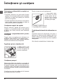
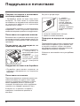
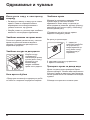
Curăţarea compartimentului pentru
detergent
Trageti afara compatimentul ridicându-l si
tragându-l spre exterior (a se vedea gura).
Spălaţi-l sub un jet de apă; această operaţie
trebuie efectuată cât mai des posibil.
Îngrijirea uşii şi a tamburului
• Lăsaţi mereu uşa
întredeschisă pentru
a evita formarea de
mirosuri neplăcute.
Curăţarea pompei
Maşina de spălat este dotată cu o pompă de
autocurăţare care nu are nevoie de întreţinere.
Se poate întâmpla însă ca unele obiecte mici
(monede, nasturi) să cadă în anticamera care
protejează pompa, situată în partea inferioară
a acesteia.
! Vericaţi ca ciclul de spălare să e încheiat
şi scoateţi stecherul din priză.
Pentru a avea acces la anticameră:
1. deşurubaţi capa-
cul rotindu-l în sens
invers acelor de ce-
asornic (a se vedea
figura). Este normal
să iasă puţină apă;
2. curăţaţi cu grijă interiorul;
3. înşurubaţi la loc capacul;
Controlarea furtunului de alimentare cu
apă
Controlaţi tubul de alimentare cel puţin o
dată pe an. Dacă prezintă crăpături sau suri
trebuie înlocuit: pe parcursul spălărilor, pre-
siunea puternică ar putea provoca crăpături
neaşteptate.
! Nu folosiţi niciodată tuburi folosite deja.
1
2
Pagina se încarcă...
Pagina se încarcă...
Pagina se încarcă...
Pagina se încarcă...
Pagina se încarcă...
Pagina se încarcă...
Pagina se încarcă...
Pagina se încarcă...
Pagina se încarcă...
Pagina se încarcă...
Pagina se încarcă...
Pagina se încarcă...
Pagina se încarcă...
Pagina se încarcă...
Pagina se încarcă...
Pagina se încarcă...
Pagina se încarcă...
Pagina se încarcă...
Pagina se încarcă...
Pagina se încarcă...
Pagina se încarcă...
Pagina se încarcă...
Pagina se încarcă...
Pagina se încarcă...
Pagina se încarcă...
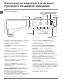
Pagina se încarcă...
Pagina se încarcă...
Pagina se încarcă...
Pagina se încarcă...
Pagina se încarcă...
Pagina se încarcă...
Pagina se încarcă...
Pagina se încarcă...
Pagina se încarcă...
Pagina se încarcă...
Pagina se încarcă...
-
 1
1
-
 2
2
-
 3
3
-
 4
4
-
 5
5
-
 6
6
-
 7
7
-
 8
8
-
 9
9
-
 10
10
-
 11
11
-
 12
12
-
 13
13
-
 14
14
-
 15
15
-
 16
16
-
 17
17
-
 18
18
-
 19
19
-
 20
20
-
 21
21
-
 22
22
-
 23
23
-
 24
24
-
 25
25
-
 26
26
-
 27
27
-
 28
28
-
 29
29
-
 30
30
-
 31
31
-
 32
32
-
 33
33
-
 34
34
-
 35
35
-
 36
36
-
 37
37
-
 38
38
-
 39
39
-
 40
40
-
 41
41
-
 42
42
-
 43
43
-
 44
44
-
 45
45
-
 46
46
-
 47
47
-
 48
48
-
 49
49
-
 50
50
-
 51
51
-
 52
52
-
 53
53
-
 54
54
-
 55
55
-
 56
56


HOTPOINT/ARISTON BHWD 125 EU Manualul utilizatorului
- Categorie
- Mașini de spălat
- Tip
- Manualul utilizatorului
în alte limbi
Lucrări înrudite
-
HOTPOINT/ARISTON WDG 862 EU Manualul utilizatorului
-
-
-
-
-
-
-
-
HOTPOINT/ARISTON CAWD 129 (EU) Manualul utilizatorului
Alte documente
-
Indesit ARMXXD 129 (EU) Manualul utilizatorului
-
-
-
-
-
-
Whirlpool AQD1072D Manualul utilizatorului
-
Indesit PWDE 7125 S (EU) Manual de utilizare
-
-