
–
–
INSTALLATION &
OPERATION
MANUAL
AIR PANEL
MODELS
P-N23NA2
P-AP160KA3
P-AP160NAE2
INSTALLATION AND OPERATION MANUAL
MANUAL DE INSTALACIÓN Y FUNCIONAMIENTO
INSTALLATIONS- UND BETRIEBSHANDBUCH
MANUEL D’INSTALLATION ET DE FONCTIONNEMENT
MANUALE D’INSTALLAZIONE E D’USOI
MANUAL DE INSTALAÇÃO E DE FUNCIONAMENTO
INSTALLATIONS- OG BETJENINGSVEJLEDNING
INSTALLATIE- EN BEDIENINGSHANDLEIDING
INSTALLATION- OCH DRIFTHANDBOK
ΕΓΧΕΙΡΙΔΙΟ ΕΓΚΑΤΑΣΤΑΣΗΣ ΚΑΙ ΛΕΙΤΟΥΡΓΙΑΣ
EN
ES
DE
FR
IT
PT
DA
NL
SV
EL
BG
CS
ET
HU
LV
LT
PL
RO
RU
РЪКОВОДСТВО ЗА ИНСТАЛИРАНЕ И ЕКСПЛОАТАЦИЯ
NÁVOD K MONTÁŽI A OBSLUZE
PAIGALDUS- JA KASUTUSJUHEND
TELEPÍTÉSI ÉS ÜZEMELTETÉSI ÚTMUTATÓ
UZSTĀDĪŠANAS UN EKSPLUATĀCIJAS ROKASGRĀMATA
MONTAVIMO IR NAUDOJIMO VADOVĄ
INSTRUKCJA MONTAŻU I OBSŁUGI
MANUAL DE INSTALARE SI OPERARE
ИНСТРУКЦИЯ ПО МОНТАЖУ И ЭКСПЛУАТАЦИИ
PMML0569 rev.1 - 03/2022


PMML0569 rev.1 - 03/2022
III
This product contains biocidal substances according to EU Reg. 528/2012
Este producto contiene sustancias biocidas según el Reg. UE 528/2012
Dieses Produkt enthält Biozide nach EU Verordnung 528/2012
Conformément à la Reg UE 528/2012, ce produit contient des substances biocides
Questo prodotto contiene sostanze biocidi ai sensi del Reg. UE 528/2012
Este produto contém substâncias biocidas de acordo com o Regulamento (UE) N.º 528/2012
Dette produkt indeholder biocider i henhold til EU-forordning nr. 528/2012
Dit product bevat biociden volgens Europese Richtlijn 528/2012.
Denna produkt innehåller biocider i enlighet med den europeiska förordningen 528/2012
Αυτό το προϊόν περιλαμβάνει βιοκτόνες ουσίες σύμφωνα με το κανονισμό ΕΕ 528/2012
Този продукт съдържа биоцидни вещества съгласно Регламент на ЕС 528/2012
Tento výrobek obsahuje biocidní látky podle nařízení EU 528/2012
Toode sisaldab biotsiide vastavalt ELi määrusele 528/2012
A termék biocid anyagokat tartalmaz az 528/2012 EU rendelet szerint
Šis produkts satur biocīdās vielas saskaņā ar ES regulu 528/2012
Šiame gaminyje yra biocidinių medžiagų, numatomų ES reglamente 528/2012
Niniejszy produkt zawiera substancje biobójcze zgodne z rozporządzeniem UE 528/2012
Acest produs conține substanțe biocide conform Regulamentului UE 528/2012
Этот продукт содержит биоцидные вещества в соответствии с Регламентом 528/2012 ЕС.
Biocide property / Propiedad biocida/Biozide Eigenschaft / Propriété biocide / Proprietà biocida / Propriedade biocida /
Biocide egenskaber / Biocide eigenschappen / Biocidegenskaper / Ιδιότητα του βιοκτόνου / Биоцидно свойство / Biocidní vlastnost /
Biotsiidne omadus / Biocid tulajdonság / Biocīdu īpašums / Biocidinė savybė / Właściwości biobójcze / Proprietate biocidă / Биоцидный
Antibacterial / Antibacteriana / Antibactérienne / Antibatterica / Antibakterielle / Antibacteriana / Antibakterielle /
Antibacteriëel / Antibakteriellt /Αντιβακτηριακές / Антибактериално / Antibakteriální / Antibakteriaalne / Antibakteriális /
Antibakteriāls / Antibakterinis / Antybakteryjne / Antibacterian / Антибактериальный
Active substance / Sustancia activa / Aktivstoe / Substances actives / Principi attivi / Substância ativa / Virksomt stof /
Actieve stof / Verksamt ämne / Δραστική ουσία / Активно вещество / Účinná látka / Toimeaine / Hatóanyag / Aktīvā viela /
Aktyvi medžiaga / Substancja czynna / Substanță activă / Активное вещество
Silver / Plata / Silver / Argent / Argento / Prata / Sølv / Zilver / Silver / Άργυρος
Сребро / Stříbro/ Hõbe / Ezüst / Sudrabs / Sidabras / Srebro / Argint / Серебро CAS Nº: 7440-22-4
These substances are NOT harmful to human health nor the environment
Estas sustancias no son perjudiciales para la salud humana ni el medio ambiente
Diese Stoffe sind nicht schädlich für die menschliche Gesundheit noch Umwelt
Ces substances ne sont pas nocives pour la santé humaine ni pour l’environnement
Queste sostanze non sono nocive per la salute umana o per l’ambiente
Estas substâncias NÃO são prejudiciais para a saúde humana nem para o ambiente
Disse stoffer er IKKE skadelige for hverken menneskers sundhed eller for miljøet
Deze stoffen zijn NIET schadelijk voor de menselijke gezondheid of voor het milieu
Dessa ämnen är INTE skadliga för människors hälsa eller för miljön
Αυτές οι ουσίες ΔΕΝ είναι επιβλαβείς στην ανθρώπινη υγεία ή στο περιβάλλον
Тези вещества НЕ са вредни за човешкото здраве и за околната среда
Tyto látky NEJSOU škodlivé pro lidské zdraví ani pro životní prostředí
Need ained EI ole kahjulikud inimese tervisele ega keskkonnale
Ezek az anyagok NEM ártalmasak az emberi egészségre és a könyezetre
Šīs vielas NAV kaitīgas cilvēka veselībai vai videi
Šios medžiagos NĖRA žalingos žmonių sveikatai ar aplinkai
Substancje te NIE są szkodliwe dla zdrowia ani środowiska naturalnego
Aceste substanțe NU sunt nocive pentru sănătatea umană și nici pentru mediul înconjurător
Эти вещества НЕ вредны для здоровья человека и окружающей среды

PMML0569 rev.1 - 03/2022
IV
INDEX
1 GENERAL INFORMATION .................................................1
2 SAFETY ................................................................................ 1
3 IMPORTANT NOTICE .........................................................2
4 NAME OF PARTS ................................................................3
5 BEFORE INSTALLATION ....................................................3
6 INSTALLATION ....................................................................4
7 TEST RUN ............................................................................ 9
8 MAINTENANCE ...................................................................10
ÍNDICE
1 INFORMACIÓN GENERAL ................................................. 11
2 SEGURIDAD ........................................................................11
3 AVISO IMPORTANTE ..........................................................12
4 NOMBRE DE LOS COMPONENTES .................................13
5 ANTES DE LA INSTALACIÓN ............................................ 13
6 INSTALACIÓN ......................................................................14
7 PRUEBA DE FUNCIONAMIENTO ...................................... 19
8 MANTENIMIENTO ............................................................... 20
INHALTSVERZEICHNIS
1 ALLGEMEINE INFORMATIONEN ......................................21
2 SICHERHEIT ........................................................................ 21
3 WICHTIGER HINWEIS ........................................................22
4 TEILEBEZEICHNUNG .........................................................23
5 VOR DER INSTALLATION .................................................. 23
6 INSTALLATION ....................................................................24
7 TESTLAUF ...........................................................................29
8 WARTUNG ...........................................................................30
TABLE DES MATIÈRES
1 INFORMATIONS GÉNÉRALES ..........................................31
2 SÉCURITÉ............................................................................31
3 REMARQUES IMPORTANTES ..........................................32
4 NOMENCLATURE DES PIÈCES ........................................ 33
5 AVANT L’INSTALLATION .....................................................33
6 INSTALLATION ....................................................................34
7 TEST DE FONCTIONNEMENT ..........................................40
8 MAINTENANCE ...................................................................41
INDICE
1 INFORMAZIONI GENERALI ...............................................43
2 SICUREZZA .........................................................................43
3 AVVISO IMPORTANTE........................................................44
4 NOME DEI COMPONENTI .................................................45
5 PRIMA DELL'INSTALLAZIONE ..........................................45
6 INSTALLAZIONE .................................................................46
7 PROVA DI FUNZIONAMENTO ...........................................51
8 MANUTENZIONE ................................................................52
ÍNDICE
1 INFORMAÇÃO GERAL ....................................................... 53
2 SEGURANÇA ....................................................................... 53
3 NOTA IMPORTANTE ...........................................................54
4 NOME DAS PEÇAS .............................................................55
5 ANTES DA INSTALAÇÃO ...................................................55
6 INSTALAÇÃO ....................................................................... 56
7 TESTE DE FUNCIONAMENTO .......................................... 61
8 MANUTENÇÃO ....................................................................62
INDHOLDSFORTEGNELSE
1 GENEREL INFORMATION .................................................63
2 SIKKERHED .........................................................................63
3 VIGTIG ANMÆRKNING ......................................................64
4 NAVN PÅ DELE....................................................................65
5 INDEN MONTERING ...........................................................65
6 INSTALLATION ....................................................................66
7 TESTKØRSEL ...................................................................... 71
8 VEDLIGEHOLDELSE .......................................................... 72
INHOUDSOPGAVE
1 ALGEMENE INFORMATIE ..................................................73
2 VEILIGHEID .........................................................................73
3 BELANGRIJKE MEDEDELING ..........................................74
4 NAMEN VAN ONDERDELEN ............................................. 75
5 VÓÓR INSTALLATIE ...........................................................75
6 INSTALLATIE .......................................................................76
7 PROEFDRAAIEN .................................................................81
8 ONDERHOUD ...................................................................... 82
INNEHÅLLSFÖRTECKNING
1 ALLMÄN INFORMATION ....................................................83
2 SÄKERHET .......................................................................... 83
3 VIKTIG ANMÄRKNING ........................................................84
4 DELARNAS NAMN ..............................................................85
5 FÖRE INSTALLATIONEN ...................................................85
6 INSTALLATION ....................................................................86
7 PROVKÖRNING ..................................................................91
8 UNDERHÅLL ........................................................................ 92
ΕΥΡΕΤΗΡΙΟ
1 ΓΕΝΙΚΕΣ ΠΛΗΡΟΦΟΡΙΕΣ .................................................. 93
2 ΑΣΦΑΛΕΙΑ ............................................................................93
3 ΣΗΜΑΝΤΙΚΗ ΠΑΡΑΤΗΡΗΣΗ ..............................................94
4 ΟΝΟΜΑΤΑ ΕΞΑΡΤΗΜΑΤΩΝ ...............................................95
5 ΠΡΙΝ ΤΗΝ ΕΓΚΑΤΑΣΤΑΣΗ .................................................. 95
6 ΕΓΚΑΤΑΣΤΑΣΗ .....................................................................96
7 ΔΟΚΙΜΑΣΤΙΚΟ ΤΡΕΞΙΜΟ ...................................................102
8 ΣΥΝΤΗΡΗΣΗ ........................................................................102
ИНДЕКС
1 ОБЩА ИНФОРМАЦИЯ .......................................................105
2 БЕЗОПАСНОСТ ..................................................................105
3 ВАЖНА БЕЛЕЖКА ..............................................................106
4 НАЗВАНИЯ НА ЧАСТИТЕ .................................................107
5 ПРЕДИ МОНТАЖ ................................................................107
6 МОНТАЖ ..............................................................................108
7 ИЗПИТАТЕЛЕН ЦИКЪЛ ..................................................... 114
8 ПОДДРЪЖКА ......................................................................114
OBSAH
1 OBECNÉ INFORMACE ....................................................... 117
2 BEZPEČNOST ..................................................................... 117
3 DŮLEŽITÉ UPOZORNĚNÍ .................................................. 118
4 NÁZEV DÍLŮ ........................................................................119
5 PŘED INSTALACÍ ................................................................119
6 INSTALACE ..........................................................................120
7 ZKUŠEBNÍ CHOD ................................................................125
8 ÚDRŽBA ...............................................................................126
INDEKS
1 ÜLDTEAVE ........................................................................... 127
2 OHUTUS ...............................................................................127
3 TÄHTIS TEADE ....................................................................128
4 OSADE NIMED ....................................................................129
5 ENNE PAIGALDAMIST .......................................................129
6 PAIGALDAMINE ..................................................................130
7 KATSETAMINE ....................................................................135
8 HOOLDUS ............................................................................ 136
TARTALOMJEGYZÉK
1 ÁLTALÁNOS INFORMÁCIÓK .............................................137
2 BIZTONSÁG ......................................................................... 137
3 FONTOS MEGJEGYZÉS ....................................................138
4 RÉSZEK NEVE ....................................................................139
5 TELEPÍTÉS ELŐTT ............................................................. 139
6 TELEPÍTÉS ..........................................................................140
7 PRÓBAÜZEM .......................................................................145
8 KARBANTARTÁS .................................................................146

PMML0569 rev.1 - 03/2022
V
INDEKSS
1 VISPĀRĪGA INFORMĀCIJA ................................................147
2 DROŠĪBA .............................................................................. 147
3 SVARĪGA PIEZĪME .............................................................. 148
4 DETAĻU NOSAUKUMS .......................................................149
5 PIRMS UZSTĀDĪŠANAS .....................................................149
6 UZSTĀDĪŠANA ....................................................................150
7 TESTA DARBĪBA ..................................................................155
8 APKOPE ...............................................................................156
INDEKSAS
1 BENDROJI INFORMACIJA ................................................. 157
2 SAUGUMAS .........................................................................157
3 SVARBI PASTABA ...............................................................158
4 DALIŲ PAVADINIMAI ...........................................................159
5 PRIEŠ MONTAVIMĄ ............................................................ 159
6 MONTAVIMAS ...................................................................... 160
7 TESTINIS PALEIDIMAS ...................................................... 165
8 TECHNINĖ PRIEŽIŪRA ......................................................166
SPIS TREŚCI
1 INFORMACJE OGÓLNE ..................................................... 167
2 BEZPIECZEŃSTWO ............................................................167
3 WAŻNE INFORMACJE ........................................................168
4 CZĘŚCI SKŁADOWE ..........................................................169
5 CZYNNOŚCI PRZEDMONTAŻOWE .................................. 169
6 MONTAŻ ............................................................................... 170
7 ROZRUCH PRÓBNY ........................................................... 176
8 KONSERWACJA .................................................................. 176
INDICE
1 INFORMAȚII GENERALE ...................................................179
2 SIGURANȚĂ .........................................................................179
3 OBSERVAȚIE IMPORTANTĂ .............................................180
4 DENUMIREA COMPONENTELOR ....................................181
5 ÎNAINTE DE INSTALARE....................................................181
6 INSTALAREA........................................................................182
7 PROBĂ DE FUNCȚIONARE ............................................... 187
8 ÎNTREȚINERE .....................................................................188
ОГЛАВЛЕНИЕ
1 ОБЩАЯ ИНФОРМАЦИЯ .................................................... 189
2 БЕЗОПАСНОСТЬ ................................................................189
3 ВАЖНОЕ УВЕДОМЛЕНИЕ ................................................ 190
4 НАЗВАНИЕ ДЕТАЛЕЙ ........................................................191
5 ПЕРЕД МОНТАЖОМ .......................................................... 191
6 УСТАНОВКА ........................................................................192
7 ПРОБНЫЙ ПУСК ................................................................198
8 ТЕХНИЧЕСКОЕ ОБСЛУЖИВАНИЕ .................................. 198


PMML0569 rev.1 - 03/2022
VII
English
Specications in this manual are subject to change without notice in order that Hitachi may bring the latest innovations to
their customers.Whilst every eort is made to ensure that all specications are correct, printing errors are beyond Hitachi’s
control; Hitachi cannot be held responsible for these errors.
Español
Las especicaciones de este manual están sujetas a cambios sin previo aviso a n de que Hitachi pueda ofrecer las
últimas innovaciones a sus clientes.
A pesar de que se hacen todos los esfuerzos posibles para asegurarse de que las especicaciones sean correctas, los
errores de impresión están fuera del control de Hitachi, a quien no se hará responsable de ellos.
Deutsch
Bei den technischen Angaben in diesem Handbuch sind Änderungen vorbehalten, damit Hitachi seinen Kunden die
jeweils neuesten Innovationen präsentieren kann.
Sämtliche Anstrengungen wurden unternommen, um sicherzustellen, dass alle technischen Informationen ohne Fehler
veröentlicht worden sind. Für Druckfehler kann Hitachi jedoch keine Verantwortung übernehmen, da sie außerhalb ihrer
Kontrolle liegen.
Français
Les caractéristiques publiées dans ce manuel peuvent être modiées sans préavis, Hitachi souhaitant pouvoir toujours
orir à ses clients les dernières innovations.
Bien que tous les eorts sont faits pour assurer l’exactitude des caractéristiques, les erreurs d’impression sont hors du
contrôle de Hitachi qui ne pourrait en être tenu responsable.
Italiano
Le speciche di questo manuale sono soggette a modica senza preavviso anché Hitachi possa orire ai propri clienti
le ultime novità.
Sebbene sia stata posta la massima cura nel garantire la correttezza dei dati, Hitachi non è responsabile per eventuali
errori di stampa che esulano dal proprio controllo.
Português
As especicações apresentadas neste manual estão sujeitas a alterações sem aviso prévio, de modo a que
a Hitachi possa oferecer aos seus clientes, da forma mais expedita possível, as inovações mais recentes.
Apesar de serem feitos todos os esforços para assegurar que todas as especicações apresentadas são correctas,
quaisquer erros de impressão estão fora do controlo da Hitachi, que não pode ser responsabilizada por estes erros even-
tuais.
Dansk
Specikationerne i denne vejledning kan ændres uden varsel, for at Hitachi kan bringe de nyeste innovationer ud til kunderne.
På trods af alle anstrengelser for at sikre at alle specikationerne er korrekte, har Hitachi ikke kontrol over trykfejl,
og Hitachi kan ikke holdes ansvarlig herfor.
Nederlands
De specicaties in deze handleiding kunnen worden gewijzigd zonder verdere kennisgeving zodat Hitachi zijn klanten
kan voorzien van de nieuwste innovaties.
Iedere poging wordt ondernomen om te zorgen dat alle specicaties juist zijn. Voorkomende drukfouten kunnen echter
niet door Hitachi worden gecontroleerd, waardoor Hitachi niet aansprakelijk kan worden gesteld voor deze fouten.
Svenska
Specikationerna i den här handboken kan ändras utan föregående meddelande för att Hitachi ska kunna leverera de
senaste innovationerna till kunderna.
Vi på Hitachi gör allt vi kan för att se till att alla specikationer stämmer, men vi har ingen kontroll över tryckfel och kan
därför inte hållas ansvariga för den typen av fel.

PMML0569 rev.1 - 03/2022
VIII
Eλλhnika
Οι προδιαγραφές του εγχειριδίου μπορούν να αλλάξουν χωρίς προειδοποίηση, προκειμένου η Hitachi να παρέχει τις
τελευταίες καινοτομίες στους πελάτες της.
Αν και έχει γίνει κάθε προσπάθεια προκειμένου να εξασφαλιστεί ότι οι προδιαγραφές είναι σωστές, η Hitachi δεν μπορεί
να ελέγξει τα τυπογραφικά λάθη και, ως εκ τούτου, δεν φέρει καμία ευθύνη για αυτά τα λάθη.
Български
Спецификациите в това ръководство подлежат на изменения без известяване, така че Hitachi да може да
предоставя на своите клиенти последните иновации.
Полагат се всички усилия, за да се гарантира, че всички спецификации са коректни, но печатните грешки са извън
обсега на контрола на Hitachi и Hitachi не може да носи отговорност за тези грешки.
Čeština
Aby společnost Hitachi mohla svým zákazníkům poskytovat nejnovější inovace, specikace uvedené v této příručce
podléhají změnám bez předchozího upozornění.
Přestože vynakládáme maximální úsilí, aby všechny specikace byly správné, tiskové chyby nespadají pod kontrolu
společnosti Hitachi, která za takové chyby nenese odpovědnost.
Eesti
Käesoleva juhendi tehnilised kirjeldused võivad muutuda ilma ette teatamiseta, selleks et Hitachi saaks tuua oma
klientideni kõige uuemad innovatsioonid.
Kuigi püütakse tagada, et kõik tehnilised kirjeldused oleksid õiged, on trükivead väljaspool Hitachi kontrolli; Hitachi ei
vastuta nende vigade eest.
Magyar
Az alábbi kézikönyvben foglalt előírások előzetes értesítés nélkül változhatnak, annak érdekében, hogy a Hitachi a
legfrissebb újításokkal szolgálhasson ügyfelei számára.
Bár minden erőfeszítést megteszünk annak érdekében, hogy minden előírás helyes legyen, a nyomtatási hibák nem
állnak a Hitachi ellenőrzése alatt; ezekért a hibákért a Hitachi nem tehető felelőssé.
Latviešu
Šīs rokasgrāmatas specikācijas var mainīties bez brīdinājuma, lai Hitachi varētu saviem klientiem piedāvāt jaunākās
inovācijas.
Lai gan tiek pieliktas visas pūles, nodrošinot, ka visas specikācijas ir pareizas, drukāšanas kļūdas ir ārpus Hitachi
kontroles; Hitachi nevar būt atbildīga par šīm kļūdām.
Lietuvių
Šio vadovo specikacijos gali būti keičiamos be įspėjimo, kad „Hitachi“ galėtų pateikti savo klientams paskutines
naujoves.
Nors dedamos visos pastangos siekiant užtikrinti, kad visos specikacijos būtų teisingos, „Hitachi“ nekontroliuoja
spausdinimo klaidų; „Hitachi“ negali būti laikoma atsakinga už tokias klaidas.
Polski
Zamieszczone w niniejszej instrukcji obsługi dane techniczne mogą ulec zmianie bez uprzedniego powiadomienia ze
względu na innowacyjne rozwiązania, jakie rma Hitachi nieustannie wprowadza z myślą o swoich klientach.
Mimo podejmowanych starań, aby zapewnić poprawność wszystkich podanych tutaj informacji, nie można wykluczyć
zaistnienia błędów drukarskich, za które rma Hitachi nie ponosi żadnej odpowiedzialności.
Română
Specicațiile din acest manual pot modicate fără noticare prealabilă, pentru ca Hitachi să poată pune la dispoziția
clienților noștri ultimele inovații.
Deși depunem toate eforturile pentru a ne asigura că toate specicațiile sunt corecte, erorile de tipărire depășesc
controlul Hitachi; Hitachi nu poate tras la răspundere pentru aceste erori.
Русский
Технические характеристики, содержащиеся в данном руководстве, могут быть изменены Hitachi без
предварительного уведомления, по причине постоянного внедрения последних инноваций.
Несмотря на то, что мы принимаем все возможные меры для актуализации технических данных, при публикации
возможны ошибки, которые Hitachi не может контролировать, и за которые не несет ответственности.

PMML0569 rev.1 - 03/2022
IX
EN English Original Version
ES Español Versión traducida
DE Deutsch Übersetzte Version
FR Français Version traduite
IT Italiano Versione tradotta
PT Português Versão traduzidal
DA Dansk Oversat version
NL Nederlands Vertaalde versie
SV Svenska Översatt version
EL Ελληνικα Μεταφρασμένη έκδοση
EN English Original Version
BG Български Преведена версия
CS Čeština Přeložená verze
ET Eesti Tõlgitud versioon
HU Magyar Lefordított változat
LV Latviešu Tulkotā versija
LT Lietuvių Versta versija
PL Polski Tłumaczenie wersji oryginalnej
RO Română Versiune tradusă
RU Русский Переведенная версия
EN
The English version is the original one; other languages are
translated from English. Should any discrepancy occur between
the English and the translated versions, the English version shall
prevail.
ES
La versión en inglés es la original, y las versiones en otros idiomas
son traducciones de la inglesa. En caso de discrepancias entre la
versión inglesa y las versiones traducidas, prevalecerá la versión
inglesa.
DE
Die englische Fassung ist das Original, und die Fassungen in an-
deren Sprachen werden aus dem Englischen übersetzt. Sollten die
englische und die übersetzten Fassungen voneinander abweichen,
so hat die englische Fassung Vorrang.
FR
La version anglaise est la version originale; les autres langues
sont traduites de l’anglais. En cas de divergence entre les versions
anglaise et traduite, la version anglaise prévaudra.
IT
La versione inglese è l’originale e le versioni in altre lingue sono
traduzioni dall’inglese. In caso di divergenze tra la versione inglese
e quelle tradotte, fa fede la versione inglese.
PT
A versão inglesa é a original; as versões em outras línguas são
traduzidas do inglês. Em caso de divergência entre a versão em
língua inglesa e as versões traduzidas, faz fé a versão em língua
inglesa.
DA
Den engelske udgave er originalen, og udgaverne på andre sprog
er oversat fra engelsk. Hvis der forekommer uoverensstemmelser
mellem den engelske og den oversatte sprogudgave, vil den engel-
ske udgave være gældende.
NL
De Engelse versie is de originele; andere talen zijn vertaald uit het
Engels. In geval van verschillen tussen de Engelse versie en de
vertaalde versies, heeft de Engelse versie voorrang.
SV
Den engelska versionen är originalet, och versionerna på andra
språk är från engelska översättningar. I händelse av bristande
överensstämmelse mellan den engelska och den översatta ver-
sionerna, skall den engelska versionen vara giltig.
EL
Η αγγλική έκδοση είναι το πρωτότυπο και οι εκδόσεις σε
άλλες γλώσσες μεταφράζονται από τα αγγλικά. Σε περίπτωση
που διαπιστωθούν διαφορές μεταξύ της αγγλικής και της
μεταφρασμένης έκδοσης, η αγγλική έκδοση είναι επικρατέστερη.
BG
Версията на английски език е оригиналната; версиите на
останалите езици са в превод от английски език. При различие
между английската версия и преводна версия на друг език за
меродавна се счита английската версия.
CS
Originální verze tohoto dokumentu je v angličtině; ostatní jazykové
varianty jsou z angličtiny přeložené. Pokud mezi anglickou a ja-
koukoli jinou jazykovou verzí dojde k rozporu, bude převažovat
anglická verze.
ET
Originaalversioon on ingliskeelne; teised keeled on tõlge inglise
keelest. Vastuolude korral ingliskeelse ja tõlkeversioonide vahel
kehtib eesõiguslikult ingliskeelne versioon.
HU
Az eredeti változat az angol; az egyéb nyelvű változatok angolról
lettek fordítva. Amennyiben az angol és a fordított verziók között
bármilyen eltérés mutatkozik, az angol nyelvű változat a mérvadó.
LV
Angļu valodas versija ir oriģināla; citas valodas tiek tulkotas no
angļu valodas. Ja starp angļu valodu un tulkoto versiju rodas
jebkādas neatbilstības, noteicošais ir angļu valodas variants.
LT
Versija anglų kalba yra originali; versijos kitomis kalbomis yra
išverstos iš anglų kalbos. Jei yra neatitikimų tarp versijos anglų
kalba ir verstinių versijų, pirmenybė teikiama versijai anglų kalba.
PL
Wersja angielska jest wersją oryginalną - wszystkie pozostałe
stanowią jej tłumaczenie na odpowiednie języki. W przypadku
stwierdzenia jakichkolwiek rozbieżności między oryginałem a jego
tłumaczeniem, rozstrzygająca jest wersja w języku angielskim.
RO
Versiunea originală este cea în limba engleză; versiunile în alte
limbi sunt traduse din limba engleză. Dacă există vreo discrepanță
între versiunile în limba engleză și versiunea tradusă, prevalează
versiunea în limba engleză.
RU
Английская версия является оригинальной; другие языки
переведены с английского. В случае любого расхождения
между английской и переведенной версиями,
английская версия имеет преимущественную силу.


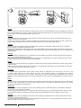
1 GENERAL INFORMATION
1.1 GENERAL NOTES
No part of this publication may be reproduced, copied, led
or transmitted in any shape or form without the permission of
Johnson Controls-Hitachi Air Conditioning Spain, S.A.U.
Within the policy of continuous improvement of its products,
Johnson Controls-Hitachi Air Conditioning Spain, S.A.U.
reserves the right to make changes at any time without prior
notication and without being compelled to introducing them into
products previously sold. This document may therefore have
been subject to amendments during the life of the product.
Hitachi makes every eort to oer correct, up-to-date
documentation. Despite this, printing errors cannot be controlled
by Hitachi and are not its responsibility.
As a result, some of the images or data used to illustrate this
document may not refer to specic models. No claims will be
accepted based on the data, illustrations and descriptions
included in this manual.
No type of modication must be made to the equipment without
prior, written authorisation from the manufacturer.
2 SAFETY
2.1 SYMBOLS USED
During normal air conditioning system design work or unit
installation, greater attention must be paid in certain situations
requiring particular care in order to avoid injuries and damage to
the unit, the installation or the building or property.
Situations that jeopardise the safety of those in the surrounding
area or that put the unit itself at risk will be clearly indicated in
this manual.
To indicate these situations, a series of special symbols will be
used to clearly identify these situations.
Pay close attention to these symbols and to the messages
following them, as your safety and that of others depends on it.
!DANGER
• The text following this symbol contains information and
instructions relating directly to your safety, in addition to
hazards or unsafe practices which could result in severe
personal injuries or death.
• Not taking these instructions into account could lead to serious,
very serious or even fatal injuries to you and others in the
proximities of the unit.
In the texts following the danger symbol you can also nd
information on safe procedures during unit installation.
!CAUTION
• The text following this symbol contains information and instructions
relating directly to your safety, in addition to hazards or unsafe
practices which could result in minor personal injury or product or
property damage.
• Not taking these instructions into account could lead to minor injuries
to you and others in the proximities of the unit.
• Not taking these instructions into account could lead to unit damage.
In the texts following the caution symbol you can also nd
information on safe procedures during unit installation.
?NOTE
• The text following this symbol contains information or instructions that
may be of use or that require a more thorough explanation.
• Instructions regarding inspections to be made on unit parts or systems
may also be included.
GENERAL INFORMATION
PMML0569 rev.1 - 03/2022
1
EN

2.2 ADDITIONAL INFORMATION ABOUT SAFETY
!DANGER
• Hitachi is not able to foresee all the circumstances which may
result in a potential danger.
• Do not pour water in the indoor or outdoor unit. These products
are tted with electric components. If water comes into contact
with electric components, this will cause a serious electric
shock.
• Do not handle or adjust the safety devices inside the indoor and
outdoor units. The handling or adjustment of these devices may
result in serious accident.
• Do not open the service cover or access panel of the indoor and
outdoor units without disconnecting the main supply.
• In the event of re, switch off the mains, put out the re
immediately and contact your service supplier.
• Check that the earth cable is correctly connected.
• Connect the unit to a circuit breaker of the specied capacity.
!CAUTION
• Refrigerant leaks may hinder respiration as the gas displaces the air
in the room. It is assumed that this heat pump air conditioner will be
operated and serviced by English speaking people. If this is not the
case, the customer should be add safety, caution and operating signs
in the native language.
• Fit the indoor unit, the outdoor unit, the remote control and the cable
at a minimum of 3 metres away from sources of strong radiation from
electromagnetic waves, such as medical equipment.
• Do not use sprays, such as insecticides, varnishes or enamels or any
other inammable gas within a metre of the system.
• If the circuit breaker or supply fuse of the unit comes on frequently,
stop the system and contact the service suppler.
• Do not carry out maintenance or inspection work yourself. This work
must be carried out by qualied service personnel with suitable tools
and resources for the work.
• Do not place any foreign material (branches, sticks, etc.) in the air
inlet or outlet of the unit. These units are tted with high speed fans
and contact with any object is dangerous.
• This appliance must be used only by adult and capable people,
having received the technical information or instructions to handle this
appliance properly and safely.
• Children should be supervised to ensure that they do not play with
the appliance.
• Install the unit in a place not accessible by the general public.
?NOTE
• The air in the room should be renewed and the room ventilated every
3 or 4 hours.
• The system tter and specialist shall provide anti-leak safety in
accordance with local regulations.
• The installer and system specialist shall secure safety against the
refrigerant leakage according to local regulations or standards. The
following standards may be applicable, if local regulations are not
available. International Organization for Standardization, ISO5149 or
European Standard, EN378 or Japan Standard, KHKS0010.
• Electrical wiring must comply with national and local regulations.
Contact your local authority in regards to standards, rules, regulations,
etc.
3 IMPORTANT NOTICE
This air conditioner has been designed for standard air
conditioning for human beings. For use in other applications,
please contact your Hitachi dealer or service contractor.
The air conditioning system should only be installed by qualied
personnel, with the necessary resources, tools and equipment,
who are familiar with the safety procedures required to
successfully carry out the installation.
The supplementary information about the purchased products is
available through de QR-Code printed in the front cover. In case
that no access to the website or les are not readable, please
contact your Hitachi dealer or distributor.
PLEASE READ THE MANUAL AND DOWNLOADED
FILES THROUGHT THE QR-CODE CAREFULLY BEFORE
STARTING TO WORK ON THE INSTALLATION. Failure to
observe the instructions for installation, use and operation
described in this documentation may result in operating failure
including potentially serious faults, or even the destruction of the
air conditioning system.
It is assumed that the air conditioning system will be installed
and maintained by responsible personnel trained for the
purpose. If this is not the case, the customer should include all
the safety, caution and operating signs in the native language of
the personnel responsible.
Do not install the unit in the following places, as this may lead to
a re, deformities, rusting or faults:
• Places where oil is present (including oil for machinery).
• Places with a high concentration of sulphurous gas, such as
spas.
• Places where ammable gases may be generated or
circulate.
• Places with a saline, acidic or alkaline atmosphere.
Do not install the unit in places where silicon gas is present. Any
silicon gas deposited on the surface of the heat exchanger will
repel water. As a result, the condensate water will splash out
of the collection tray and into the electrical box. Water leaks or
electrical faults may eventually be caused.
Do not install the unit in a place where the current of expelled
air directly aects animals or plants as they could be adversely
aected.
There are detailed information about unit installation, service
space, wiring diagrams, electrical connection, refrigerant charge,
in the corresponding chapter, please read the corresponding
chapter carefully before starting work on the installation.
IMPORTANT NOTICE
PMML0569 rev.1 - 03/2022
2

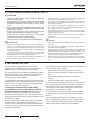
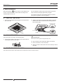
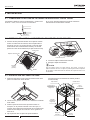
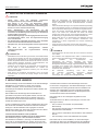
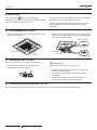
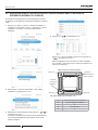
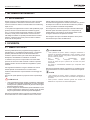
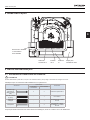
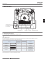
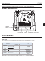
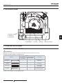
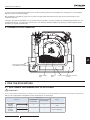
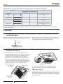
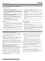
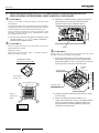
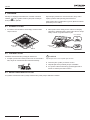
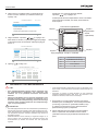
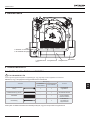
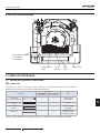
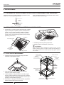
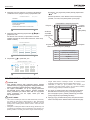
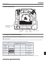
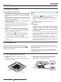
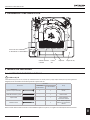
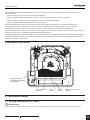
4 NAME OF PARTS
DRAIN
>PS<
HS-HB
DIP
Air panel P-N23NA2 /
P-AP160KA3 /
P-AP160NAE2
Air inlet grille Air inlet Air outlet Cover for corner pocket
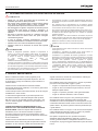
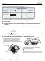
5 BEFORE INSTALLATION
5.1 FACTORY-SUPPLIED ACCESSORIES
!CAUTION
When the air panel is unpacked, place it on insulation material, etc. to protect the sealing insulation from scratches.
Check to ensure that the accessories are packed with the air panel.
Accessory
Quantity
Purpose
P-N23NA2
P-AP160KA3 P-AP160NAE2
Long Screw
(M6 Cross Screw) 4 4 For xing air panel
Connecting cable
(4 poles) - 1 For sensor
Wiring cover - 1 For protection of relay
connector
Cable band - 3 For clamping wiring cover
and relay connector
If any of these accessories are not packed in the packing, please contact your contractor.
NAME OF PARTS
PMML0569 rev.1 - 03/2022
3
EN

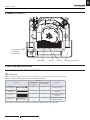
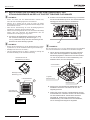
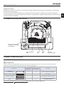
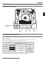
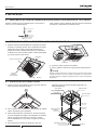
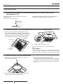
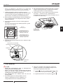
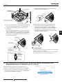
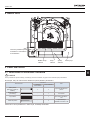
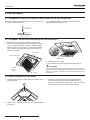
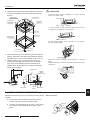
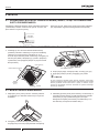
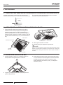
6 INSTALLATION
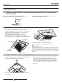
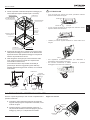
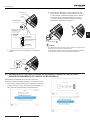
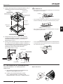
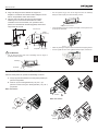
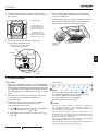
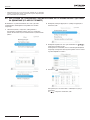
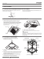
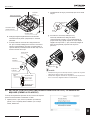
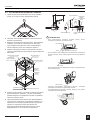
6.1 CHECK THE INDOOR UNIT HEIGHT FROM THE FALSE CEILING SURFACE
Check the distance between the indoor unit and the false
ceiling. It is 12+5mm as shown below.
12+5
0
Ceiling surface
Indoor unit
If not, adjust the distance by using the checking scale with
maintaining the levelness of the indoor unit.
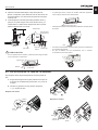
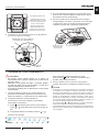
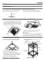
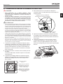
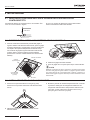
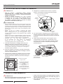
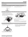
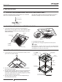
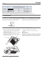
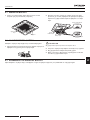
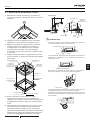
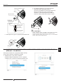
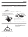
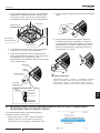
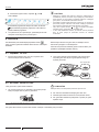
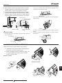
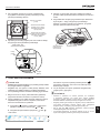
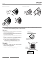
6.2 REMOVING AIR INTAKE GRILLE FROM AIR PANEL
1 Push both ends of knobs at the air inlet grille toward the
arrow direction, open the air inlet grille until the angle of
approximately 45° from the air panel surface. After lifting
the air inlet grille keeping it inclined, draw the air inlet grille
forward. (Remove the lament tape (4 portions) xing the air
lter).
P-AP160NAE
P-AP160NA1
45°
45°
Knob
Air inlet grille
Corner
pocket cover
(4 portions)
Air panel
Supporting string
2 Lift the grille keeping it inclined.
3 Draw the grille towards the open space after lifting.
?NOTE
Perform the attaching work in the reverse procedure of removing for
install the air intake grille. The air inlet grille can be attached from any
4 directions by rotating it. The air intake grille direction can be selected
freely.
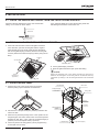
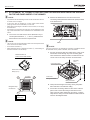
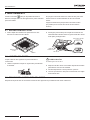
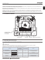
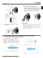
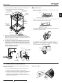
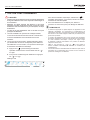
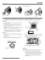
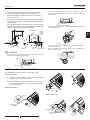
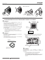
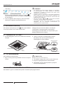
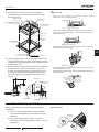
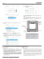
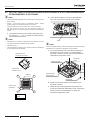
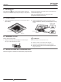
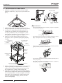
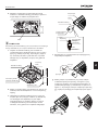
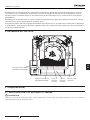
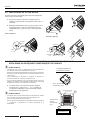
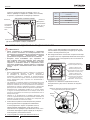
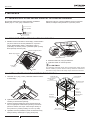
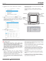
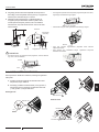
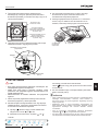
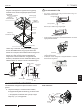
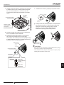
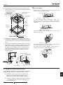
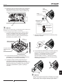
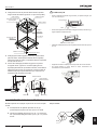
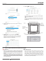
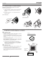
6.3 INSTALLING AIR PANEL
1 Remove the cover of the corner pocket (4 portions).
Remove pulling A part toward the arrow direction.
A
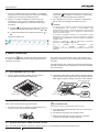
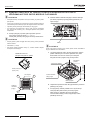
2 Pull down the U-shaped hook (at 2 positions) located at the
indoor unit side.
3 Mount the air panel temporarily. Fit the corner position of the
refrigerant pipe connection at the indoor unit and the position
stamped as “Ref. Pipe “. Then, catch the C-shaped hinges (2
portions) onto the U-shaped hooks (2 portions).
4 Fix the air panel to the xing plate by factory supplied long
screws (M6 cross screws).
Long screws (Q'ty 4)
C-shaped hinge
Stamp refrigerant
pipe
Electrical box
Refrigerant pipe
connections
Indoor unit
Air panel
U-shaped hook
Fixing plate
INSTALLATION
PMML0569 rev.1 - 03/2022
4

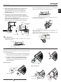
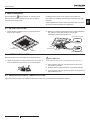
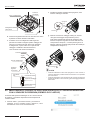
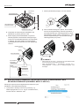
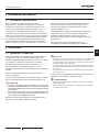
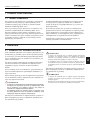
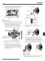
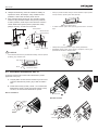
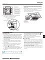
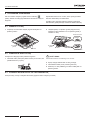
5 Tighten the long screws until touching the stopper to the
xing plate. Check to ensure that the distance between the
xing plate undersurface and the corner panel undersurface
is 26mm.
6 When tightening the long screws to prevent air leakage
and to be no gap between the false ceiling surface and
the indoor unit, the inner circumference of the air panel
(the position to attach the air inlet grille) may be slightly
deformed. However, it is not abnormality.
26
12
+5
0
False ceiling
Indoor unit
Fixing plate
(indoor unit)
Long screw
Corner
panel
!CAUTION
• If tighten long screws insufcient, may cause something wrong as
below.
Air Leakage
Smudge Dewing
• If any gap has even though tighten long screws sufcient,
readjust the height of indoor unit.
No gap shall exist
• It’s able to adjust the indoor unit height by using wrench from the
corner pocket.
Wrench
• Too considerable adjustment of height cause dewing from drain-pan.
• Do not turn the air louver by hand. If moved, the louver mechanism
would be damaged.
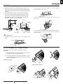
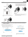
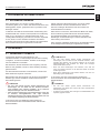
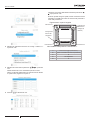
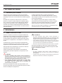
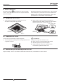
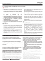
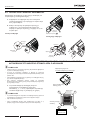
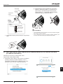
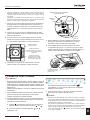
6.4 ATTACHMENT OF CORNER COVER
Attach the corner covers after the air panel is mounted
completely.
a. Catch the band at the rear side of the corner cover onto
the projection at the air panel as shown.
b. Insert and push the xing hooks (2 portions) at Ⓐ to the
air panel and insert and push the xing hook (1 portion)
at Ⓑ to the air panel.
Corner with sensor
Projection
Band
Fixing hook
Fixing hook
A
A
A
B
B
Corner without sensor
A
B
B
A
A
Projection
Band
Fixing hook
Fixing
hook
INSTALLATION
PMML0569 rev.1 - 03/2022
5
EN

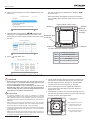
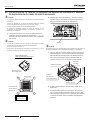
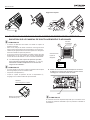
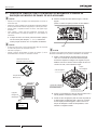
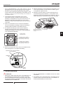
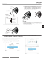
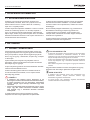
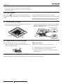
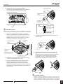
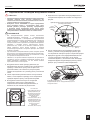
6.5 ATTACHMENT OF CORNER COVER WITH MOTION SENSOR AND RADIATION SENSOR
ON THE AIR PANEL MODEL P-AP160NAE2
?NOTE
• Pay attention that the detecting function will be decreased if the lens
for motion sensor smudges.
• In this case, wipe off smudges by a cotton swab soaked alcohol
(Isopropyl alcohol is recommended) or a soft cloth.
• When wiping off smudges on the lens for motion sensor, do not apply
excessive force.
• If excessive force is applied, the resin lens may be damaged so that
may cause malfunctions such as misdetection or undetectable of the
motion.
a. The corner cover with sensor can be attached to any of
corners (three directions, Ⓐ , Ⓑ and Ⓓ). Determine the
best location in line with user's requirements.
?NOTE
• The corner cover encasing the Motion Sensor should be placed in the
corner closest to the wired controller.
• Do not attach at location Ⓒ.
• When the Motion Sensor is attached at location Ⓐ, control setting on
the wired controller is not necessary.
A
BC
D
Removed form of
Corner Cover with Sensor
Attachment Position
Stamp (A~D)
A
BC
DAir Panel
Refrigerant Pipe
Connections
Do not
attach here.
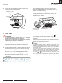
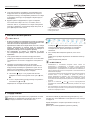
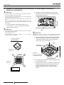
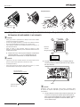
b. Remove the electrical box cover and connect the
connecting cable (attached inside the air panel) at CN33
in the electrical box.
CN33
?NOTE
The CN10 connector is only available for connection of the Motion Sensor
kit SOR-MSK and for panels P-N23NA2, and P-AP160KA3.
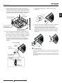
c. Run the connecting cable from CN33 to the corner cover
with motion sensor through top of the mounting plate.
Then measure the distance 100mm to 200mm from the
corner cover to the relay connector as shown below.
100~200mm
Connecting Cable
Relay Connector
Mounting
Plate
Indoor Unit
Wiring Connection
d. Clamp the extra length of the relay wire by the plastic
band and store it at inside the ceiling.
e. Access the connecting cable from the corner of the air
panel. Then connect the wiring for the sensor to the
relay connector. After making the connection, cover the
relay with the wiring cover and install the cable bands as
shown in the diagram below.
INSTALLATION
PMML0569 rev.1 - 03/2022
6

Air Panel
Corner
Connecting Cable
Corner Cover
with Sensor
Relay
Connector Cable Band
Wiring Cover
Cable Band
f. Install the corner band onto the projection as shown
below.
Projection
Band
g. As you insert wiring into the corner, insert the other two
xing hooks corresponding to points Ⓐ (into the squared
slots on the air panel) and slide the corner cover in the
direction of the arrows at points Ⓐ. Then, insert the xing
hook into the squared slot (of the air panel) at point Ⓑ.
Fixing hook
Fixing hook
A
A
A
B
B
?NOTE
• Catch securely the band onto the projection. If not, the corner cover
may fall down when removing it so that may cause injury.
• Catch securely the xing hooks of the corner cover to the air panel. If
not, the xing hooks will be damaged.
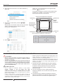
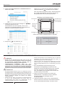
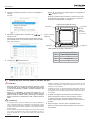
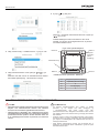
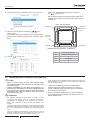
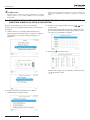
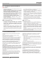
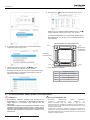
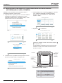
6.6 CONTROL SETTINGS AFTER INSTALLING CORNER COVER WITH MOTION SENSOR
(PC-ARFG-E EXAMPLE)
Depending on the location of the corner with motion sensor,
setting on the wired controller is also necessary.
1 Press “Menu”, then “Service Installation” and enter de
Password “0-0-0-0”. Press the “Installation Menu” and the
“Test Run” menu will be displayed.
Cool Fan Speed Louver Menu
Service&Installation
Screen DisplaySetting
Function Menu
Menu
Help
Enter Password
OK
6000
OK Confirm Back
Service & Installation
Check Menu
Installation Menu
Service Menu
Back
OK Enter
(Mon) 16:30
INSTALLATION
PMML0569 rev.1 - 03/2022
7
EN

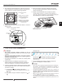
2 Select “Function Selection” from the “Installation Menu” and
press “OK”.
Installation Menu
OK Enter Back
Input/Output
Thermistor Selection
Thermistor Calibration in Controller
Function Selection
Test Run
(Mon) 16:30
3 Select the indoor unit by pressing “ ” and press “OK”.
This screen is not displayed when only one indoor unit is
connected to the wired remote controller. In this case, follow
the step 4.
Function Selection
00-00
ALL
00-01
00-02
OK Select Back
4 Press “ ” and select “L1”.
b1: Heating temperature compensation due to uneven heat load
Function Selection : 00-00
b1 b7 bd C5
b2 b8 bE C6
b3 b9 C1 C7
b5 bb C3 C9
b4 bA C2 C8
b6 bC C4 CA
01 00 00 00
00 00 00 00
00 00 00 00
00 00 00 00
00 00 00 00
00 00 00 00
01: No compensation
Back
OK Select
b-J
K-P
q-S
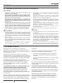
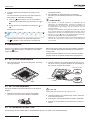
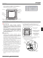
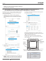
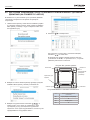
Set “L1” according to the table below by pressing “ ”
and press “OK”.
When the products are shipped, the menu key should be
set to “L1=00”, which indicates motion sensor is located at
stamp A.
Figure without corner covers
Do not install in the “Stamp C” position
Attached
location (as
shipped)
Stamp D Stamp A
Stamp C Stamp B
Refrigerant pipe
connection
L1 Attaching Place (Stamp)
00 A [No Setting Required]
01 B
02 Not Available
03 D
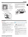
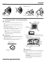
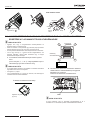
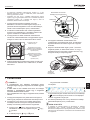
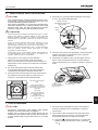
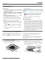
6.7 WIRING CONNECTION FOR AIR PANEL
!DANGER
• Before the electrical wiring work, turn OFF the power source. If
the connectors are connected without turning OFF the power
source, the auto swing louver can not activate.
• Air panel P-AP160KA3: In case of attaching this air panel on the
RCI-FSR series indoor unit, remove the relay wiring attached to
indoor unit PCB. After that, connect the wiring attached to the air
panel directly to the PCB as described above.
!CAUTION
• All electrical installation work must be performed by certied
personnel and all work must be complete and conform to local and
NEC (National Electrical Code) standards. Failure to uphold these
standards can result in damage, re, electrical shock, and serious or
fatal injury.
• When opening and closing the electrical box cover, work so that it
does not contact the suspension wire. If the suspension wire breaks,
the air inlet grille and air lter may fall. It may cause injury.
• Perform securely the electrical wiring work. If the electrical work is not
completed, heat generation at the connection, a re or an electrical
shock may occur.
• Make sure that the wires are securely xed in order not to apply an
external force to the terminal connections of the wirings. If xing is not
completed, heat generation or a re will occur.
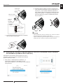
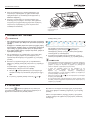
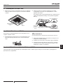
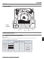
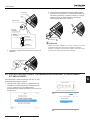
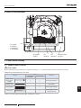
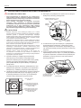
1 The air panel has motor wiring for auto louver. Remove the
tape securing the wiring and make sure to pass it through
the cable band as shown in the gure on the right before
connecting it to the connector (CN17) on the PCB.
2 After connecting the connector, tighten the cable band
to secure the wiring. After wiring is secured, attach the
electrical box cover.
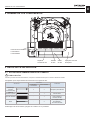
3 The following connectors are used in the air panel. Remove
the tape xing the wiring connectors on the air panel and pull
out them as shown in the gure below.
>PS<
HS-HB
Electrical box
Motor wiring for auto louver (on
air panel) (connector for low
voltage: 18 poles, white)
Motor wiring for auto louver (on
indoor unit) (Connector for low
voltage: 18 poles, white)
Condition without air
intake grille
INSTALLATION
PMML0569 rev.1 - 03/2022
8

4 Connect them with the wiring connectors to CN17 in the
electrical box as the following gure.
21
21
Motor wiring for auto
louver (on air panel)
Cable band
Connector
(CN17)
5 After completing the wiring connection of the air panel,
attach the air inlet grille. Perform the attaching work in the
reverse procedure of removing.
6 Fasten the other end of the support string to the
corresponding hole at part Ⓐ in the panel as shown. The
fact that the air inlet grille is square allows it to be rotated to
be xed from any direction.
Supporting string
Hole to secure the
support string to the
air panel
Part Ⓐ
7 TEST RUN
!DANGER
• Do not put any foreign materials within the air inlet grille
operation range. It may lead to injury or damage.
• Keep the wire from re or sharp edge. Breaking wire may cause
of injury due to air inlet grille or air lter falling.
• If the air inlet grille or the air lter falls, it may cause injury.
1 After completing installation of the air panel, Test Run should
be performed according to installation and maintenance
manual for the indoor unit.
2 Perform the checking work for the louver during the test run.
Do not move the louver by hand. If moved, the auto-swing
mechanism will be damaged.
a. Press “ ” (run / stop), and the operation is started.
Select the air ow direction by “ ” or “ ”.
b. The louver angle is changed by pressing “ ” or “ ”.
LCD Indication
The auto swing operation will be started to select “ ”
(auto swing). At this time, LCD indication displays the swing
repeatedly.
3 If there is a louver that does not move, check the connection
of the louver wiring connector (CN17).
?NOTE
• Adequate and optimal airow is dependent on application and
installation practices which include positioning of ofce equipment,
room structure, and ofce cubicle or furniture layout. Adjust airow
for maximum comfort.
• The position of the louvers may not coincide with the louver position
indicator on the LCD during auto swing operation. When adjusting
the louver angle, set it according to the louver position on the LCD.
• Even if the “ ” or “ ” are pressed to stop the auto swing function, the
louver is not stopped immediately.
• If the cooling operation is performed with greater than 80% relative
humidity, condensation may form on the air panel or louver surfaces.
TEST RUN
PMML0569 rev.1 - 03/2022
9
EN

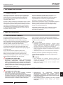
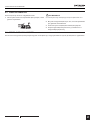
8 MAINTENANCE
When the indication, (lter) is shown on the display of the
remote control switch, take out the air lter according to the
indicated steps for each unit.
Do not operate the system without the air lter to protect the
indoor unit heat exchanger against being clogged.
Turn OFF the main power switch before taking out the lter.
(The previous operation mode may appear).
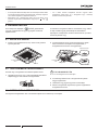
8.1 TAKE OUT THE FILTER
1 Open the air inlet grille after pushing the two knobs toward
the arrow mark.
Knob
Air inlet grille
2 Hold the lower side of the air inlet grille keeping it inclined.
Remove the hooks of air lter from the air inlet grille and
remove the air lter.
Hook
Upper part of lter
Lower part of lter
Air inlet grille
Air lter
Hook
8.2 CLEAN THE FILTER
Clean the air lter according to the following steps:
1 Use a vacuum cleaner or let water ow onto the air lter for
removing the dirt from the air lter.
!CAUTION
Do not use hot water higher than approximately 40ºC.
2 Dry the air lter in the shade after shaking o moisture.
3 Do not use cleaner or other chemicals.
4 After the air lter is dried, attach and close correctly to the air
inlet grille.
8.3 RESET OF FILTER INDICATION
After cleaning the air lter, reset the lter sign according the remote control procedure.
MAINTENANCE
PMML0569 rev.1 - 03/2022
10
Pagina se încarcă...
Pagina se încarcă...
Pagina se încarcă...
Pagina se încarcă...
Pagina se încarcă...
Pagina se încarcă...
Pagina se încarcă...
Pagina se încarcă...
Pagina se încarcă...
Pagina se încarcă...
Pagina se încarcă...
Pagina se încarcă...
Pagina se încarcă...
Pagina se încarcă...
Pagina se încarcă...
Pagina se încarcă...
Pagina se încarcă...
Pagina se încarcă...
Pagina se încarcă...
Pagina se încarcă...
Pagina se încarcă...
Pagina se încarcă...
Pagina se încarcă...
Pagina se încarcă...
Pagina se încarcă...
Pagina se încarcă...
Pagina se încarcă...
Pagina se încarcă...
Pagina se încarcă...
Pagina se încarcă...
Pagina se încarcă...
Pagina se încarcă...
Pagina se încarcă...
Pagina se încarcă...
Pagina se încarcă...
Pagina se încarcă...
Pagina se încarcă...
Pagina se încarcă...
Pagina se încarcă...
Pagina se încarcă...
Pagina se încarcă...
Pagina se încarcă...
Pagina se încarcă...
Pagina se încarcă...
Pagina se încarcă...
Pagina se încarcă...
Pagina se încarcă...
Pagina se încarcă...
Pagina se încarcă...
Pagina se încarcă...
Pagina se încarcă...
Pagina se încarcă...
Pagina se încarcă...
Pagina se încarcă...
Pagina se încarcă...
Pagina se încarcă...
Pagina se încarcă...
Pagina se încarcă...
Pagina se încarcă...
Pagina se încarcă...
Pagina se încarcă...
Pagina se încarcă...
Pagina se încarcă...
Pagina se încarcă...
Pagina se încarcă...
Pagina se încarcă...
Pagina se încarcă...
Pagina se încarcă...
Pagina se încarcă...
Pagina se încarcă...
Pagina se încarcă...
Pagina se încarcă...
Pagina se încarcă...
Pagina se încarcă...
Pagina se încarcă...
Pagina se încarcă...
Pagina se încarcă...
Pagina se încarcă...
Pagina se încarcă...
Pagina se încarcă...
Pagina se încarcă...
Pagina se încarcă...
Pagina se încarcă...
Pagina se încarcă...
Pagina se încarcă...
Pagina se încarcă...
Pagina se încarcă...
Pagina se încarcă...
Pagina se încarcă...
Pagina se încarcă...
Pagina se încarcă...
Pagina se încarcă...
Pagina se încarcă...
Pagina se încarcă...
Pagina se încarcă...
Pagina se încarcă...
Pagina se încarcă...
Pagina se încarcă...
Pagina se încarcă...
Pagina se încarcă...
Pagina se încarcă...
Pagina se încarcă...
Pagina se încarcă...
Pagina se încarcă...
Pagina se încarcă...
Pagina se încarcă...
Pagina se încarcă...
Pagina se încarcă...
Pagina se încarcă...
Pagina se încarcă...
Pagina se încarcă...
Pagina se încarcă...
Pagina se încarcă...
Pagina se încarcă...
Pagina se încarcă...
Pagina se încarcă...
Pagina se încarcă...
Pagina se încarcă...
Pagina se încarcă...
Pagina se încarcă...
Pagina se încarcă...
Pagina se încarcă...
Pagina se încarcă...
Pagina se încarcă...
Pagina se încarcă...
Pagina se încarcă...
Pagina se încarcă...
Pagina se încarcă...
Pagina se încarcă...
Pagina se încarcă...
Pagina se încarcă...
Pagina se încarcă...
Pagina se încarcă...
Pagina se încarcă...
Pagina se încarcă...
Pagina se încarcă...
Pagina se încarcă...
Pagina se încarcă...
Pagina se încarcă...
Pagina se încarcă...
Pagina se încarcă...
Pagina se încarcă...
Pagina se încarcă...
Pagina se încarcă...
Pagina se încarcă...
Pagina se încarcă...
Pagina se încarcă...
Pagina se încarcă...
Pagina se încarcă...
Pagina se încarcă...
Pagina se încarcă...
Pagina se încarcă...
Pagina se încarcă...
Pagina se încarcă...
Pagina se încarcă...
Pagina se încarcă...
Pagina se încarcă...
Pagina se încarcă...
Pagina se încarcă...
Pagina se încarcă...
Pagina se încarcă...
Pagina se încarcă...
Pagina se încarcă...
Pagina se încarcă...
Pagina se încarcă...
Pagina se încarcă...
Pagina se încarcă...
Pagina se încarcă...
Pagina se încarcă...
Pagina se încarcă...
Pagina se încarcă...
Pagina se încarcă...
Pagina se încarcă...
Pagina se încarcă...
Pagina se încarcă...
Pagina se încarcă...
Pagina se încarcă...
Pagina se încarcă...
Pagina se încarcă...
Pagina se încarcă...
Pagina se încarcă...
Pagina se încarcă...
Pagina se încarcă...
Pagina se încarcă...
Pagina se încarcă...
Pagina se încarcă...
Pagina se încarcă...
Pagina se încarcă...
Pagina se încarcă...
Pagina se încarcă...
Pagina se încarcă...
Pagina se încarcă...
-
 1
1
-
 2
2
-
 3
3
-
 4
4
-
 5
5
-
 6
6
-
 7
7
-
 8
8
-
 9
9
-
 10
10
-
 11
11
-
 12
12
-
 13
13
-
 14
14
-
 15
15
-
 16
16
-
 17
17
-
 18
18
-
 19
19
-
 20
20
-
 21
21
-
 22
22
-
 23
23
-
 24
24
-
 25
25
-
 26
26
-
 27
27
-
 28
28
-
 29
29
-
 30
30
-
 31
31
-
 32
32
-
 33
33
-
 34
34
-
 35
35
-
 36
36
-
 37
37
-
 38
38
-
 39
39
-
 40
40
-
 41
41
-
 42
42
-
 43
43
-
 44
44
-
 45
45
-
 46
46
-
 47
47
-
 48
48
-
 49
49
-
 50
50
-
 51
51
-
 52
52
-
 53
53
-
 54
54
-
 55
55
-
 56
56
-
 57
57
-
 58
58
-
 59
59
-
 60
60
-
 61
61
-
 62
62
-
 63
63
-
 64
64
-
 65
65
-
 66
66
-
 67
67
-
 68
68
-
 69
69
-
 70
70
-
 71
71
-
 72
72
-
 73
73
-
 74
74
-
 75
75
-
 76
76
-
 77
77
-
 78
78
-
 79
79
-
 80
80
-
 81
81
-
 82
82
-
 83
83
-
 84
84
-
 85
85
-
 86
86
-
 87
87
-
 88
88
-
 89
89
-
 90
90
-
 91
91
-
 92
92
-
 93
93
-
 94
94
-
 95
95
-
 96
96
-
 97
97
-
 98
98
-
 99
99
-
 100
100
-
 101
101
-
 102
102
-
 103
103
-
 104
104
-
 105
105
-
 106
106
-
 107
107
-
 108
108
-
 109
109
-
 110
110
-
 111
111
-
 112
112
-
 113
113
-
 114
114
-
 115
115
-
 116
116
-
 117
117
-
 118
118
-
 119
119
-
 120
120
-
 121
121
-
 122
122
-
 123
123
-
 124
124
-
 125
125
-
 126
126
-
 127
127
-
 128
128
-
 129
129
-
 130
130
-
 131
131
-
 132
132
-
 133
133
-
 134
134
-
 135
135
-
 136
136
-
 137
137
-
 138
138
-
 139
139
-
 140
140
-
 141
141
-
 142
142
-
 143
143
-
 144
144
-
 145
145
-
 146
146
-
 147
147
-
 148
148
-
 149
149
-
 150
150
-
 151
151
-
 152
152
-
 153
153
-
 154
154
-
 155
155
-
 156
156
-
 157
157
-
 158
158
-
 159
159
-
 160
160
-
 161
161
-
 162
162
-
 163
163
-
 164
164
-
 165
165
-
 166
166
-
 167
167
-
 168
168
-
 169
169
-
 170
170
-
 171
171
-
 172
172
-
 173
173
-
 174
174
-
 175
175
-
 176
176
-
 177
177
-
 178
178
-
 179
179
-
 180
180
-
 181
181
-
 182
182
-
 183
183
-
 184
184
-
 185
185
-
 186
186
-
 187
187
-
 188
188
-
 189
189
-
 190
190
-
 191
191
-
 192
192
-
 193
193
-
 194
194
-
 195
195
-
 196
196
-
 197
197
-
 198
198
-
 199
199
-
 200
200
-
 201
201
-
 202
202
-
 203
203
-
 204
204
-
 205
205
-
 206
206
-
 207
207
-
 208
208
-
 209
209
-
 210
210
-
 211
211
-
 212
212


Hitachi P-N23NA2, P-AP160KA3, P-AP160NAE2 Air Panel Cooling and Heating Manual de utilizare
- Tip
- Manual de utilizare
- Acest manual este potrivit și pentru
în alte limbi
Lucrări înrudite
-
Hitachi RPIL-(0.4-1.5)FSRE Ducted Indoor Units Manual de utilizare
-
Hitachi PC-ARCHE Eco Compact Wired Remote Controller Manual de utilizare
-
-
Miele ESW 7010 BW Manualul proprietarului
-
-
Hitachi CG28EJ Manual de utilizare
-
Hikoki C10FCH2 Manual de utilizare
-
-
Hikoki RB 36DL Manual de utilizare
-