
Cod. 060000070_Vers. 2.0 - 03_2019 / © All rights are reserved. No warranty provided on this information.
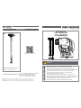
INCLUDES
1 2
3
AVVERTENZE / WARNINGS / WARNUNGEN / AVERTISSEMENTS / ADVERTENCIAS
AVISO / VAROVÁNÍ / UPOZORENJA / FIGYELMEZTETÉS / UWAGA / INSTRUCŢIUNI
VAROVANIA
IT
UK
DE
FR
ES
PT
CZ
HR
HU
PL
RO
SK
Rispettare le polarità delle connessioni e corrente massima consentita.
Please respect the polarities of connections and max current warning.
Bitte beachten Sie die Polarität der Anschlüsse und die max. Stromwarnung.
Veuillez respecter les polarités des connexions et l'avertissement de courant maximum.
Respete las polaridades de las conexiones y la máxima advertencia actual.
Por favor, respeite as polaridades das conexões e o aviso máximo atual.
Respektujte polaritu připojení a varování max.
Molimo poštujte polaritet priključaka i maksimalno upozorenje.elmeztetést.
Kérjük, vegye gyelembe a csatlakozások polaritását és a max. Aktuális gyelmeztetést.
Należy przestrzegać polaryzacji połączeń i maksymalnego bieżącego ostrzeżenia.
PlRespectați polaritățile conexiunilor și avertizarea maximă curentă.
Prosím rešpektujte polaritu pripojenia a maximálnu aktuálnu výstrahu.
FUEL CONTROLLER
FCS SENSOR
LagoGENESIS srl - Via Selenia 1. 36061 Bassano del Grappa (VI) - Italy — [email protected]- www.lagogenesis.it
LagoGENESIS reserves the right to modify and /or improve the present product specication without prior notice.
710955002 FUEL CONTROLLER UNIVERSAL RS 232 DATA HUB
710955003 FUEL CONTROLLER D.I. RS 232 DATA HUB
710955012 FUEL CONTROLLER RS 485 DATA HUB
710955013 FUEL CONTROLLER D.I. RS 485 DATA HUB
Compatible with the following products:
214520XYZ FC-XYZ Fuel Sensor
(XYZ denotes the length of the sensor)
214520XYZ
3
2
3 3
ZM7380
SAP- ABC
16 W 31
s/n G00ABCXXX
via Selenia 1, 36061
Bassano del Grappa (VI)
mod. FCS Sensor
Download the complete
FuelCONTROLLER manual here!

Rispettare le polarità delle connessioni e corrente massima consentita.
Please respect the polarities of connections and max current warning.
Please respect the polarities of connections and max current warning.
Please respect the polarities of connections and max current warning.
Please respect the polarities of connections and max current warning.
Please respect the polarities of connections and max current warning.
Please respect the polarities of connections and max current warning.
Please respect the polarities of connections and max current warning.
Please respect the polarities of connections and max current warning.
Please respect the polarities of connections and max current warning.
Please respect the polarities of connections and max current warning.
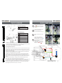
THE FCS SENSOR QUICK START GUIDE
1
2
3
4
5
6
7
FCS Code and Serial No.
Electrical Connector
Fuel SEND - Sends fuel to Engine
Fuel RETRUN– Returns fuel to tank
Fuel Return - external heater unit
Fuel Send- external heater unit
Venting valve.
Telematics
Original sensor connector
Fuel
Lines
ZM7380
SAP- ABC
16 W 31
s/n G00ABCXXX
via Selenia 1, 36061
Bassano del Grappa (VI)
mod. FCS Sensor
717620010 or 717620012 FUEL CONTROLLER
CABLE CONNECTION FCS SENSOR to FC HUB
717620011 FUEL CONTROLLER CABLE
CONNECTION FCS SENSOR to FC HUB
ZM7380
SAP- ABC
16 W 31
s/n G00ABCXXX
via Selenia 1, 36061
Bassano del Grappa (VI)
mod. FCS Sensor
Check for the most
suitable fitting kit for your
original fuel lines from
item number range:
Kits 070819001-070819013
Always terminate fuel
SEND and RETURN when
no fuel lines are present
using suitable M14 fittings
Kit 070819004
1 2
3 4
3
Insert the FCS Fuel Sensor in the
hole.
1
Disconnect the original connec-
tor ( ) and disconnect the fuel
lines ( ) from the original fuel
sensor.
2
Remove the original fuel sensor
by rotating, after having
disconnected the fuel lines ( ).
4
Connect the FCS Fuel Sensor
using the supplied connector ( )
and the wire lines to the relevant
pins on the Fuel Controller Hub
located in the cab.
Connect Fuel Controller level
gauge output ( ) to the original
fuel sensor connector ( ).
WARNING: Before connecting the elcectrical connector to the sensor, make sure the other electrical
connection in the vehicle are completed. Failure to respect this warning could result in serious damage
to the FCS Sensor. Always ensure the polarities are correct before connecting.
Refer to the Fuel Controller documentation for more information.
Connecting the FCS fuel Sensors
1. After having connected the FuelController electronic control unit in the vehicle cabin,
you will proceed to change the original tank mounted sensor with the FCS fuel sensors.
2. Make sure the length of the FCS sensor is the same as the length of the original sensor
being removed from the tank(s).
3. Insert the FCS sensor, making sure there is an O-Ring under the sensor head which
seals the sensor opening when the sensor is installed.
4. To x the sensor, make sure the “star hole” bayonet is correctly inserted and rotate
clock-wise until the sensor rotates no further and is xed in its’ installed position. In
doing so, make sure you do not apply excessive force to the plastic electrical connector.
If necessary, use a tool to be able to gain leverage to overcome the initial resistance to
rotation.
5. Screw in the fuel line ttings, ensuring you always include the supplied copper
washers and O-rings. Respect the fuel send and return indications.
6. To conclude, connect the electrical signal respecting the polarity of the FCS sensor. Pin
no. 1 of the sensor is the positive (+) signal and connects to Pin 13 or 14 (main and
secondary tanks respectively) of the FuelController electronic control unit. Pin 2 on the
FCS sensor is the negative (-) and connects to Pin 1 or 2 (main and secondary tanks
respectively) of the FuelController electronic control unit.
1
2
PIN 1 - Positive (+) Signal
PIN 2 - Negative (-) Signal
ELECTRICAL CONNECTION
PART DESCRIPTIONS
-
 1
1
-
 2
2


în alte limbi
- English: Genesis 214520XYZ Quick start guide
Alte documente
-
Ransomes HF600 Manualul proprietarului
-
Yamaha WT11 Manualul proprietarului
-
Samsung MIM-E03AN Manualul utilizatorului
-
Suzuki Jimny Manualul proprietarului
-
Ransomes USAG004 / USAD004 / 62706 Manualul proprietarului
-
Samsung AE140JXYDGH/EU Manualul utilizatorului
-
Samsung AE140JXEDEH/EU Manualul utilizatorului
-