Ubiquiti LBE-5AC-Gen2 Ghid de inițiere rapidă
- Categorie
- Antene de rețea
- Tip
- Ghid de inițiere rapidă
Acest manual este potrivit și pentru

2.4 GHz airMAX
®
ac
BaseStation Radio with
Dedicated Wi-Fi Management
Model: R2AC

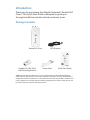
Introduction
Thank you for purchasing the Ubiquiti Networks® Rocket®2AC
Prism®. This Quick Start Guide is designed to guide you
through installation and also includes warranty terms.
Package Contents
Rocket2AC Prism GPS Antenna
2.4 GHz airMAX
®
ac
BaseStation Radio with
Dedicated Wi-Fi Management
Model: R2AC
Gigabit PoE (24V, 0.5A)
with Mounting Bracket
Power Cord
Quick Start Guide
TERMS OF USE: Ubiquiti radio devices must be professionally installed. Shielded Ethernet
cable and earth grounding must be used as conditions of product warranty. TOUGHCable
™
is
designed for outdoor installations. It is the professional installer’s responsibility to follow local
country regulations, including operation within legal frequency channels, output power, and
Dynamic Frequency Selection (DFS) requirements.

Installation Requirements
• The GPS Antenna needs to have clear line of sight to thesky
for proper GPS operation.
• Shielded Category 5 (or above) cabling with drain wire
should be used for all outdoor wired Ethernet connections
and should be grounded through the AC ground of the PoE.
We recommend that you protect your networks from
harmful outdoor environments and destructive ESD events
with industrial‑grade, shielded Ethernet cable from Ubiquiti
Networks. For more details, visit
www.ubnt.com/toughcable
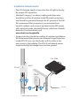
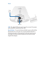
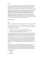
• Surge protection should be used for all outdoor installations.
We recommend that you use two Ethernet Surge Protectors,
model ETH‑SP, one near the Rocket and the other at the
entry point to the building. The ETH‑SP will absorb power
surges and safely discharge them into the ground.
To LAN
ETH-SP
ETH-SP
ES-8-150W
R2AC*
* Shown without the antenna.

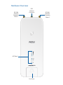
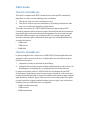
Hardware Overview
GPS
Antenna
Connector
RP-SMA
Antenna
Connector:
Chain 1
RP-SMA
Antenna
Connector:
Chain 0
LED Panel
Port Cover

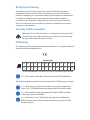
LED Panel
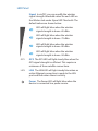
Signal In airOS®, you can modify the wireless
signal strength threshold values for each LED on
the Wireless tab under Signal LED Thresholds. The
default values are shown below:
LED will light blue when the wireless
signal strength is above ‑65 dBm.
LED will light blue when the wireless
signal strength is above ‑73 dBm.
LED will light blue when the wireless
signal strength is above ‑80 dBm.
LED will light blue when the wireless
signal strength is above ‑94 dBm.
GPS GPS The GPS LED will light steady blue when the
GPS signal strength is sufficient. This requires a
minimum of three satellite connections.
LAN LAN The LAN LED will light steady blue when an
active Ethernet connection is made to the LAN
port and flash when there is activity.
Power The Power LED will light blue when the
device is connected to a power source.

Ports
M/N: R2AC
24V 0.5A GigE PoE
FCC ID: SWX-R2ACN
IC: 6545A-R2ACN
LAN Port
Reset
Button
LAN The Gigabit Ethernet port is used to connect the power
and should be connected to the LAN.
Reset Button To reset to factory defaults, press and hold the
Reset button for more than 10 seconds while the Rocket is
already poweredon. Alternatively, the Rocket may be reset
remotely via a Reset button located on the bottom of the
Gigabit PoE adapter.

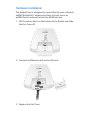
Hardware Installation
The Rocket Prism is designed to mount directly onto a Ubiquiti
airMAX RocketDish
™
antenna for Point‑to‑Point use or an
airMAX Sector antenna for Point‑to‑MultiPoint use.
1. Lift the release latch on the bottom of the Rocket and slide
the Port Cover off.
2. Connect an Ethernet cable to the LAN port.
M/N: R2AC
24V 0.5A GigE PoE
FCC ID: SWX-R2ACN
IC: 6545A-R2ACN
3. Replace the Port Cover.

4. Connect the RF cables (included with the antenna) to the
RP-SMA Connectors located on top of the Rocket.
Skip this step if you are using the RocketDish RD‑2G24.
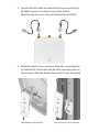
5. Attach the Rocket to an antenna. Align the mounting tabs
on the back of the Rocket with the four mounting slots on
the antenna. Slide the Rocket down until it locks into place.
CHAIN 1
GPS
CHAIN 0
CHAIN 1
GPS
CHAIN 0
CHAIN 1
GPS
CHAIN 0
CHAIN 1
GPS
CHAIN 0
Mounting on a RocketDish Mounting on a Sector Antenna

6. Attach the RF cables to the RF connectors on the Rocket or
antenna as needed.
CHAIN 1
GPS
CHAIN 0
CHAIN 1
GPS
CHAIN 0
CHAIN 1
GPS
CHAIN 0
CHAIN 1
GPS
CHAIN 0
Connecting to a RocketDish Connecting to a Sector Antenna
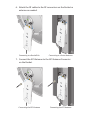
7. Connect the GPS Antenna to the GPS Antenna Connector
on the Rocket.
CHAIN 1
GPS
CHAIN 0
CHAIN 1
GPS
CHAIN 0
CHAIN 1
GPS
CHAIN 0
CHAIN 1
GPS
CHAIN 0
Connecting the GPS Antenna Connecting the GPS Antenna

8. Slide the protective shroud over the Rocket until it locks
into place.
Skip this step if you are using the RocketDish RD‑2G24.
CHAIN 1
GPS
CHAIN 0
CHAIN 1
GPS
CHAIN 0
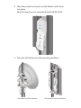
9. Place the GPS Antenna on the mounting hardware.
CHAIN 1
GPS
CHAIN 0
CHAIN 1
GPS
CHAIN 0
CHAIN 1
GPS
CHAIN 0
CHAIN 1
GPS
CHAIN 0
Placement on a Dish Antenna Placement on a Sector Antenna

Connecting Power
Connect the power using one of the following options:
• Using the included Gigabit PoE Adapter: Go to Connecting to
the PoE Adapter.
• Using a separate PoE switch: Connect the Ethernet cable
from the Rocket’s LAN port to a PoE‑enabled Ethernet port
on the switch.
WARNING: The switch port must comply with the
power specifications listed in the Specifications
section of this Quick Start Guide.
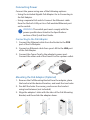
Connecting to the PoE Adapter
1. Connect the Ethernet cable from the Rocket to the POE
port of the PoE Adapter.
2. Connect an Ethernet cable from your LAN to the LAN port
of the PoE Adapter.
3. Connect the Power Cord to the adapter’s power port.
Connect the other end of the Power Cord to a power outlet.
Mounting the PoE Adapter (Optional)
1. Remove the PoE Mounting Bracket from the adapter, place
the bracket at the desired location, and mark the two holes.
2. Pre‑drill the holes if necessary, and secure the bracket
using two fasteners (not included).
3. Align the adapter’s slots with the tabs of the PoE Mounting
Bracket, and then slide the adapterdown.

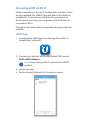
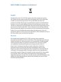
Accessing airOS via Wi‑Fi
Verify connectivity in the airOS Configuration Interface. There
are two methods, the UNMS
™
App and Web Portal. Both are
available for 15 minutes immediately after you power on
the Rocket. If necessary, you can power cycle the Rocket to
re‑enable its Wi‑Fi.
Proceed to the section that corresponds with your preferred
method:
UNMS App
1. Download the UNMS app from the AppStore (iOS) or
Google Play
™
(Android).
2. Connect your device’s Wi‑Fi to the Rocket SSID named:
R2AC:<MAC Address>
Note: Ensure that your Wi‑Fi connection has DHCP
enabled.
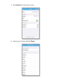
3. Launch the app.
4. Tap the Rocket listed on the Connections screen.

5. Tap Connect on the Login screen.
192.168.172.1
R2AC:F09FC12EXXXX
Rocket 2AC Prism
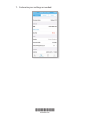
6. Select your Country and tap Done.

7. Customize your settings as needed.
*640-00318-04*
640-00318-04

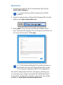
Web Portal
1. Connect your device’s Wi‑Fi to the Rocket SSID named:
R2AC:<MAC Address>
Note: Ensure that your Wi‑Fi connection has DHCP
enabled.
2. Launch a web browser and type the following URL into the
address bar: http://setup.ubnt.com
3. Enter ubnt in the Username and Password fields. Select
your Country and Language. You must agree to the Terms of
Use to use the product. Click Login.
Note:
The Country setting for U.S. product versions is
restricted to a choice of Canada, Puerto Rico, or the
U.S. to ensure compliance with FCC/IC regulations.
The airOS Configuration Interface will appear, allowing you
to customize your settings as needed. For additional details
on the airOS Configuration Interface, refer to the User Guide
available at www.ubnt.com/download/airmax

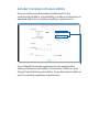
Installer Compliance Responsibility
Devices must be professionally installed and it is the
professional installer's responsibility to make sure the device is
operated within local country regulatory requirements.
Since Ubiquiti Networks equipment can be paired with a
variety of antennas and cables, the Antenna, Cable Loss, and
Output Power fields are provided to the professional installer to
assist in meeting regulatory requirements.

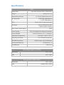
Specifications
R2AC
Dimensions 88 x 40 x 230 mm (3.47 x 1.58 x 9.06")
Weight 400 g (14.11 oz)
Networking Interface (1) 10/100/1000 Ethernet Port
RF Connectors (2) RP‑SMA (Waterproof)
(1) GPS (Waterproof)
LEDs Power, LAN, (4) Signal Strength
Enclosure Die‑Cast Aluminum with
White Powder Coating
Max. Power Consumption 9.5W
Power Supply 24V, 0.5A Gigabit PoE Adapter (Included)
Power Method Passive PoE (Pairs 4, 5+; 7, 8 Return)
Operating Temperature ‑40 to 80° C (‑40 to 176° F)
Operating Humidity 5 to 95% Noncondensing
ESD/EMP Protection ± 24kV Contact / Air for Ethernet
Shock and Vibrations ETSI300‑019‑1.4
Certications CE, FCC, IC
Operating Frequency (MHz)
Worldwide 2412 ‑ 2472
USA 2412 ‑ 2462
Management Radio (MHz)
Worldwide 5150 ‑ 5250
USA U‑NII‑3: 5725 ‑ 5850

Safety Notices
1. Read, follow, and keep these instructions.
2. Heed all warnings.
3. Only use attachments/accessories specified by the manufacturer.
WARNING: Do not use this product in a location that can
be submerged by water.
WARNING: Avoid using this product during an electrical
storm. There may be a remote risk of electric shock from
lightning.
Electrical Safety Information
1. Compliance is required with respect to voltage, frequency, and current
requirements indicated on the manufacturer’s label. Connection to a
different power source than those specified may result in improper
operation, damage to the equipment or pose a fire hazard if the
limitations are not followed.
2. There are no operator serviceable parts inside this equipment. Service
should be provided only by a qualified service technician.
3. This equipment is provided with a detachable power cord which has
an integral safety ground wire intended for connection to a grounded
safety outlet.
a. Do not substitute the power cord with one that is not the provided
approved type. Never use an adapter plug to connect to a 2‑wire
outlet as this will defeat the continuity of the grounding wire.
b. The equipment requires the use of the ground wire as a part of the
safety certification, modification or misuse can provide a shock
hazard that can result in serious injury or death.
c. Contact a qualified electrician or the manufacturer if there
are questions about the installation prior to connecting the
equipment.
d. Protective earthing is provided by Listed AC adapter. Building
installation shall provide appropriate short‑circuit backup
protection.
e. Protective bonding must be installed in accordance with local
national wiring rules and regulations.

Limited Warranty
UBIQUITI NETWORKS, Inc (“UBIQUITI NETWORKS”) warrants that the
product(s) furnished hereunder (the “Product(s)”) shall be free from defects
in material and workmanship for a period of one (1) year from the date
of shipment by UBIQUITI NETWORKS under normal use and operation.
UBIQUITI NETWORKS’ sole and exclusive obligation and liability under
the foregoing warranty shall be for UBIQUITI NETWORKS, at its discretion,
to repair or replace any Product that fails to conform to the above
warranty during the above warranty period. The expense of removal and
reinstallation of any Product is not included in this warranty. The warranty
period of any repaired or replaced Product shall not extend beyond its
original term.
Warranty Conditions
The above warranty does not apply if the Product:
(I) has been modified and/or altered, or an addition made thereto,
except by Ubiquiti Networks, or Ubiquiti Networks’ authorized
representatives, or as approved by Ubiquiti Networks in writing;
(II) has been painted, rebranded or physically modified in any way;
(III) has been damaged due to errors or defects in cabling;
(IV) has been subjected to misuse, abuse, negligence, abnormal physical,
electromagnetic or electrical stress, including lightning strikes, or
accident;
(V) has been damaged or impaired as a result of using third party
firmware;
(VI) has no original Ubiquiti MAC label, or is missing any other original
Ubiquiti label(s); or
(VII) has not been received by Ubiquiti within 30 days of issuance of
the RMA.
In addition, the above warranty shall apply only if: the product has been
properly installed and used at all times in accordance, and in all material
respects, with the applicable Product documentation; all Ethernet cabling
runs use CAT5 (or above), and for outdoor installations, shielded Ethernet
cabling is used, and for indoor installations, indoor cabling requirements
are followed.
Returns
No Products will be accepted for replacement or repair without obtaining
a Return Materials Authorization (RMA) number from UBIQUITI NETWORKS
during the warranty period, and the Products being received at UBIQUITI
NETWORKS’ facility freight prepaid in accordance with the RMA process of
UBIQUITI NETWORKS. Products returned without an RMA number will not
be processed and will be returned freight collect or subject to disposal.
Information on the RMA process and obtaining an RMA number can be
found at: www.ubnt.com/support/warranty

Disclaimer
EXCEPT FOR ANY EXPRESS WARRANTIES PROVIDED HEREIN, UBIQUITI
NETWORKS, ITS AFFILIATES, AND ITS AND THEIR THIRD PARTY DATA,
SERVICE, SOFTWARE AND HARDWARE PROVIDERS HEREBY DISCLAIM
AND MAKE NO OTHER REPRESENTATION OR WARRANTY OF ANY KIND,
EXPRESS, IMPLIED OR STATUTORY, INCLUDING, BUT NOT LIMITED TO,
REPRESENTATIONS, GUARANTEES, OR WARRANTIES OF MERCHANTABILITY,
ACCURACY, QUALITY OF SERVICE OR RESULTS, AVAILABILITY,
SATISFACTORY QUALITY, LACK OF VIRUSES, QUIET ENJOYMENT, FITNESS
FOR A PARTICULAR PURPOSE AND NON‑INFRINGEMENT AND ANY
WARRANTIES ARISING FROM ANY COURSE OF DEALING, USAGE OR
TRADE PRACTICE IN CONNECTION WITH SUCH PRODUCTS AND SERVICES.
BUYER ACKNOWLEDGES THAT NEITHER UBIQUITI NETWORKS NOR
ITS THIRD PARTY PROVIDERS CONTROL BUYER’S EQUIPMENT OR THE
TRANSFER OF DATA OVER COMMUNICATIONS FACILITIES, INCLUDING
THE INTERNET, AND THAT THE PRODUCTS AND SERVICES MAY BE
SUBJECT TO LIMITATIONS, INTERRUPTIONS, DELAYS, CANCELLATIONS
AND OTHER PROBLEMS INHERENT IN THE USE OF COMMUNICATIONS
FACILITIES. UBIQUITI NETWORKS, ITS AFFILIATES AND ITS AND THEIR THIRD
PARTY PROVIDERS ARE NOT RESPONSIBLE FOR ANY INTERRUPTIONS,
DELAYS, CANCELLATIONS, DELIVERY FAILURES, DATA LOSS, CONTENT
CORRUPTION, PACKET LOSS, OR OTHER DAMAGE RESULTING FROM ANY
OF THE FOREGOING. In addition, UBIQUITI NETWORKS does not warrant
that the operation of the Products will be error‑free or that operation will
be uninterrupted. In no event shall UBIQUITI NETWORKS be responsible
for damages or claims of any nature or description relating to system
performance, including coverage, buyer’s selection of products (including
the Products) for buyer’s application and/or failure of products (including
the Products) to meet government or regulatory requirements.
Limitation of Liability
EXCEPT TO THE EXTENT PROHIBITED BY LOCAL LAW, IN NO EVENT WILL
UBIQUITI OR ITS SUBSIDIARIES, AFFILIATES OR SUPPLIERS BE LIABLE FOR
DIRECT, SPECIAL, INCIDENTAL, CONSEQUENTIAL OR OTHER DAMAGES
(INCLUDING LOST PROFIT, LOST DATA, OR DOWNTIME COSTS), ARISING
OUT OF THE USE, INABILITY TO USE, OR THE RESULTS OF USE OF THE
PRODUCT, WHETHER BASED IN WARRANTY, CONTRACT, TORT OR OTHER
LEGAL THEORY, AND WHETHER OR NOT ADVISED OF THE POSSIBILITY OF
SUCH DAMAGES.
Pagina se încarcă ...
Pagina se încarcă ...
Pagina se încarcă ...
Pagina se încarcă ...
Pagina se încarcă ...
Pagina se încarcă ...
Pagina se încarcă ...
Pagina se încarcă ...
-
 1
1
-
 2
2
-
 3
3
-
 4
4
-
 5
5
-
 6
6
-
 7
7
-
 8
8
-
 9
9
-
 10
10
-
 11
11
-
 12
12
-
 13
13
-
 14
14
-
 15
15
-
 16
16
-
 17
17
-
 18
18
-
 19
19
-
 20
20
-
 21
21
-
 22
22
-
 23
23
-
 24
24
-
 25
25
-
 26
26
-
 27
27
-
 28
28


Ubiquiti LBE-5AC-Gen2 Ghid de inițiere rapidă
- Categorie
- Antene de rețea
- Tip
- Ghid de inițiere rapidă
- Acest manual este potrivit și pentru
în alte limbi
- English: Ubiquiti LBE-5AC-Gen2 Quick start guide
- italiano: Ubiquiti LBE-5AC-Gen2 Guida Rapida
Lucrări conexe
-
Ubiquiti LAP-120 Ghid de inițiere rapidă
-
-
-
-
Ubiquiti M3 GPS Rocket M Series Ghid de inițiere rapidă
-
Ubiquiti Networks XR5 Manual de utilizare
-
-
-
-