Makita LS1040 Manual de utilizare
- Categorie
- Ferăstraie mitre
- Tip
- Manual de utilizare
Acest manual este potrivit și pentru

1
v
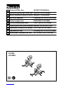
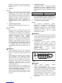
GB Compound Miter Saw INSTRUCTION MANUAL
SI
Kombinirana zajeralna žaga s krožno žago
NAVODILO ZA UPORABO
AL
Sharrë e përbërë për prerje me kënd
MANUALI I PËRDORIMIT
BG Настолен циркуляр
РЪКОВОДСТВО ЗА ЕКСПЛОАТАЦИЯ
HR Potezno-nagibna pila PRIRUČNIK S UPUTAMA
MK Потезна комбинирана пила
У
ПАТСТВО ЗА УПОТРЕБА
RO
Ferăstrău pentru tăieri oblice combinate
MANUAL DE INSTRUCŢIUNI
RS
Комбинована тестера за косо резање
У
ПУТСТВО ЗА УПОТРЕБУ
RUS Торцовочная Пила
РУКОВОДСТВО ПО ЭКСПЛУАТАЦИИ
UA Комбінована торцювальна пила ІНСТРУКЦІЯ З ЕКСПЛУАТАЦІЇ
LS1040
LS1040S


5
ENGLISH (Original instructions)
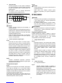
Explanation of general view
1-1. Auxiliary plate
1-2. Hex bolt
1-3. Base
2-1. Auxiliary plate
2-2. Base
2-3. Hex bolt
2-4. Nut
3-1. Holder
4-1. Holder
4-2. Adjuster
4-3. Screw
5-1. Stopper pin
6-1. Bolt
7-1. Blade guard
8-1. Blade guard
9-1. Kerf board
9-2. Turn base
10-1. Socket wrench
10-2. Adjusting bolt
11-1. Top surface of turn base
11-2. Periphery of blade
11-3. Guide fence
12-1. Pointer
12-2. Lock lever
12-3. Grip
12-4. Miter scale
13-1. Lever
14-1. Lever
14-2. Bevel scale
14-3. Pointer
15-1. Lever
15-2. Lock-off button
16-1. Lock-off button
16-2. Switch trigger
17-1. Center cover
17-2. Socket wrench
17-3. Hex bolt
17-4. Blade guard
18-1. Socket wrench
18-2. Shaft lock
19-1. Blade case
19-2. Arrow
19-3. Saw blade
19-4. Arrow
20-1. Spindle
20-2. Flange
20-3. Saw blade
20-4. Flange
20-5. Hex bolt
20-6. Ring
21-1. Dust nozzle
21-2. Dust bag
21-3. Fastener
22-1. Support
22-2. Turn base
23-1. Sub-fence
24-1. Sub-fence
25-1. Vise rod
25-2. Screw
25-3. Vise knob
25-4. Vise arm
25-5. Guide fence
25-6. Holder assembly
25-7. Holder
26-1. Vise knob
26-2. Projection
26-3. Vise shaft
26-4. Base
27-1. Holder assembly
27-2. Holder
28-1. Holder assembly
28-2. Rod 12
31-1. Vise
31-2. Spacer block
31-3. Guide fence
31-4. Aluminum extrusion
31-5. Spacer block
32-1. Set plate
32-2. Holder
32-3. Screw
33-1. Stopper pin
35-1. Hex bolt
36-1. Triangular rule
36-2. Grip
36-3. Guide fence
37-1. Arm
37-2. Lever
37-3. 0 ゚ adjusting bolt
37-4. Hex nut
38-1. Triangular rule
38-2. Saw blade
38-3. Top surface of turn base
39-1. Arm
39-2. Bevel scale
39-3. Pointer
39-4. Turn base
40-1. Lever
40-2. Arm
40-3. Pointer
40-4. 45 ゚ bevel angle adjusting bolt
41-1. Limit mark
42-1. Screwdriver
42-2. Brush holder cap
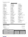
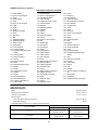
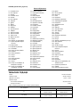
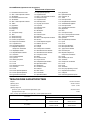
SPECIFICATIONS
Model LS1040 / LS1040S
Blade diameter 255 mm - 260 mm
Blade body thickness 1.6 mm - 2.4 mm
Hole diameter
For all countries other than European countries 25.4 mm and 25 mm
For European countries 30 mm
Max. Cutting capacities (H x W) with blade 260 mm in diameter
Miter angle
Bevel angle 0° 45° (left and right)
93 mm x 95 mm 93 mm x 67 mm
0° 69 mm x 135 mm 69 mm x 95 mm
53 mm x 95 mm 49 mm x 67 mm
45° (left) 35 mm x 135 mm 35 mm x 94 mm

6
No load speed (min-1) 4,600
Dimensions (L x W x H) 530 mm x 476 mm x 532 mm
Net weight 12.4 kg
Safety class /II
• Due to our continuing program of research and development, the specifications herein are subject to change without notice.
• Specifications may differ from country to country.
• Weight according to EPTA-Procedure 01/2003
END217-5
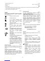
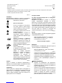
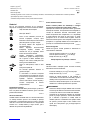
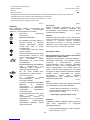
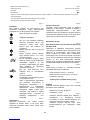
Symbols
The following show the symbols used for the equipment.
Be sure that you understand their meaning before use.
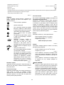
・ Read instruction manual.
・ DOUBLE INSULATION
・ To avoid injury from flying debris, keep
holding the saw head down, after
making cuts, until the blade has come
to a complete stop.
・ Do not place hand or fingers close to
the blade.
・ For your safety, remove the chips,
small pieces, etc. from the table top
before operation.
・ Always set SUB-FENCE to left position
when performing left bevel cuts. Failure
to do so may cause serious injury to
operator.
・ To loosen the bolt, turn it clockwise.
・ Only for EU countries
Do not dispose of electric equipment
together with household waste
material!
In observance of the European
Directive, on Waste Electric and
Electronic Equipment and its
implementation in accordance with
national law, electric equipment that
have reached the end of their life must
be collected separately and returned to
an environmentally compatible
recycling facility.
ENE004-1
Intended use
The tool is intended for accurate straight and miter
cutting in wood. With appropriate saw blades, aluminum
can also be sawed.
ENF002-2
Power supply
The tool should be connected only to a power supply of
the same voltage as indicated on the nameplate, and
can only be operated on single-phase AC supply. They
are double-insulated and can, therefore, also be used
from sockets without earth wire.
For Model LS1040
ENF100-1
For public low-voltage distribution systems of
between 220 V and 250 V.
Switching operations of electric apparatus cause
voltage fluctuations. The operation of this device under
unfavorable mains conditions can have adverse effects
to the operation of other equipment. With a mains
impedance equal or less than 0.29 Ohms it can be
presumed that there will be no negative effects. The
mains socket used for this device must be protected
with a fuse or protective circuit breaker having slow
tripping characteristics.
ENG905-1
Noise
The typical A-weighted noise level determined
according to EN61029:
Sound pressure level (LpA) : 91 dB (A)
Sound power level (LWA) : 101 dB (A)
Uncertainty (K) : 3 dB (A)
Wear ear protection
ENG900-1
Vibration
The vibration total value (tri-axial vector sum)
determined according to EN61029:
Vibration emission (ah) : 2.5 m/s2 or less
Uncertainty (K) : 1.5 m/s2
ENG901-1
• The declared vibration emission value has been
measured in accordance with the standard test
method and may be used for comparing one tool
with another.
• The declared vibration emission value may also be
used in a preliminary assessment of exposure.
WARNING:
• The vibration emission during actual use of the
power tool can differ from the declared emission
value depending on the ways in which the tool is
used.
• Be sure to identify safety measures to protect the
operator that are based on an estimation of
exposure in the actual conditions of use (taking
account of all parts of the operating cycle such as
the times when the tool is switched off and when it
is running idle in addition to the trigger time).

7
ENH003-15
For European countries only
EC Declaration of Conformity
Makita declares that the following Machine(s):
Designation of Machine:
Compound Miter Saw
Model No./ Type: LS1040,LS1040S
Conforms to the following European Directives:
2006/42/EC
They are manufactured in accordance with the following
standard or standardized documents:
EN61029
The technical file in accordance with 2006/42/EC is
available from:
Makita, Jan-Baptist Vinkstraat 2, 3070, Belgium
30. 6. 2014
000331
Yasushi Fukaya
Director
Makita, Jan-Baptist Vinkstraat 2, 3070, Belgium
GEA010-1
General Power Tool Safety
Warnings
WARNING Read all safety warnings and all
instructions. Failure to follow the warnings and
instructions may result in electric shock, fire and/or
serious injury.
Save all warnings and instructions for
future reference.
ENB034-10
MITER SAW SAFETY WARNINGS
1. Keep hands out of path of saw blade. Avoid
contact with any coasting blade. It can still
cause severe injury.
2. Check the saw blade carefully for cracks or
deformation before operation.
Replace damaged blades immediately.
3. Replace the kerf board when worn.
4. Use only saw blades specified by the
manufacturer which conform to EN847-1.
5. Do not use saw blades manufactured from
high speed steel.
6. Wear eye protection.
7. Wear hearing protection to reduce the risk of
hearing loss.
8. Wear gloves for handling saw blade (saw
blades shall be carried in a holder wherever
practicable) and rough material.
9. Connect miter saws to a dust collecting
device when sawing.
10. Select saw blades in relation to the material to
be cut.
11. Do not use the saw to cut other than wood,
aluminum or similar materials.
12. Always secure all moving portions before
carrying the tool. When lifting or carrying
the tool, do not use the guard as a carrying
handle.
13. Do not operate saw without guards in place.
Check blade guard for proper closing before
each use. Do not operate saw if blade guard
does not move freely and close instantly.
Never clamp or tie the blade guard into the
open position.
14. Keep the floor area free of loose material e.g.
chips and cut-offs.
15. Use only saw blades that are marked with a
maximum speed equal to or higher than the
no load speed marked on the tool.
16. When the tool is fitted with a laser or LED, do
not replace the laser or LED with a different
type. Ask an authorized service center for repair.
17. Never remove any cut-offs or other parts of
the workpiece from the cutting area whilst the
tool is running with an unguarded saw blade.
18. Do not perform any operation freehand. The
workpiece must be secured firmly against the turn
base and guide fence with the vise during all
operations. Never use your hand to secure the
workpiece.
19. Ensure that the tool is stable before each cut.
20. Fix the tool to a work bench, if needed.
21. Support long workpieces with appropriate
additional supports.
22. Never cut so small workpiece which cannot
be securely held by the vise. Improperly held
workpiece may cause kickback and serious
personal injury.
23. Never reach around saw blade.
24. Turn off tool and wait for saw blade to stop
before moving workpiece or changing
settings.
25.
Unplug tool before changing blade or servicing.
26. Stopper pin which locks the cutter head down
is for carrying and storage purposes only and
not for any cutting operations.
27. Do not use the tool in the presence of
flammable liquids or gases. The electrical
operation of the tool could create an explosion
and fire when exposed to flammable liquids or
gases.
28. Use only flanges specified for this tool.
29. Be careful not to damage the arbor, flanges
(especially the installing surface) or bolt.
Damage to these parts could result in blade
breakage.

8
30. Make sure that the turn base is properly
secured so it will not move during operation.
31. For your safety, remove the chips, small
pieces, etc. from the table top before
operation.
32. Avoid cutting nails. Inspect for and remove all
nails from the workpiece before operation.
33. Make sure the shaft lock is released before
the switch is turned on.
34. Be sure that the blade does not contact the
turn base in the lowest position.
35. Hold the handle firmly. Be aware that the saw
moves up or down slightly during start-up and
stopping.
36. Make sure the blade is not contacting the
workpiece before the switch is turned on.
37. Before using the tool on an actual workpiece,
let it run for a while. Watch for vibration or
wobbling that could indicate poor installation
or a poorly balanced blade.
38. Wait until the blade attains full speed before
cutting.
39. Stop operation immediately if you notice
anything abnormal.
40. Do not attempt to lock the trigger in the on
position.
41. Be alert at all times, especially during
repetitive, monotonous operations. Do not be
lulled into a false sense of security. Blades
are extremely unforgiving.
42. Always use accessories recommended in this
manual. Use of improper accessories such as
abrasive wheels may cause an injury.
43. Take care when slotting.
44. Some dust created from operation contains
chemicals known to cause cancer, birth
defects or other reproductive harm. Some
examples of these chemicals are:
• lead from lead-based-painted material and,
• arsenic and chromium from chemically-
treated lumber.
Your risk from these exposures varies,
depending on how often you do this type of
work. To reduce your exposure to these
chemicals: work in a well ventilated area and
work with approved safety equipment, such as
those dust masks that are specially designed
to filter out microscopic particles.
45. To reduce the emitted noise, always be sure
that the blade is sharp and clean.
46. The operator is adequately trained in the use,
adjustment and operation of the machine.
SAVE THESE INSTRUCTIONS.
WARNING:
DO NOT let comfort or familiarity with product
(gained from repeated use) replace strict adherence
to safety rules for the subject product. MISUSE or
failure to follow the safety rules stated in this
instruction manual may cause serious personal
injury.
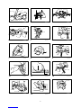
INSTALLATION
Installing auxiliary plate
Fig.1
Fig.2
Install the auxiliary plate using the notch in the tool's
base and secure it by tightening the hex bolt.
Installing the holders
Fig.3
Fig.4
Install the holders on both sides of the base and secure
them with screws.
Adjust the adjusters so that they contact the floor
surface.
NOTE:
In some countries, the holders may not have feet.
Bench mounting
When the tool is shipped, the handle is locked in the
lowered position by the stopper pin. Release the
stopper pin by lowering the handle slightly and pulling
the stopper pin.
Fig.5
This tool should be bolted with two bolts to a level and
stable surface using the bolt holes provided in the tool's
base. This will help prevent tipping and possible injury.
Fig.6

9
FUNCTIONAL DESCRIPTION
CAUTION:
• Always be sure that the tool is switched off and
unplugged before adjusting or checking function
on the tool.
Blade guard
Fig.7
When lowering the handle, the blade guard rises
automatically. The guard is spring loaded so it returns to
its original position when the cut is completed and the
handle is raised. NEVER DEFEAT OR REMOVE THE
BLADE GUARD OR THE SPRING WHICH ATTACHES
TO THE GUARD.
In the interest of your personal safety, always maintain
the blade guard in good condition. Any irregular
operation of the blade guard should be corrected
immediately. Check to assure spring loaded return
action of guard. NEVER USE THE TOOL IF THE
BLADE GUARD OR SPRING ARE DAMAGED,
FAULTY OR REMOVED. DOING SO IS HIGHLY
DANGEROUS AND CAN CAUSE SERIOUS
PERSONAL INJURY.
If the see-through blade guard becomes dirty, or
sawdust adheres to it in such a way that the blade is no
longer easily visible, unplug the saw and clean the
guard carefully with a damp cloth. Do not use solvents
or any petroleum-based cleaners on the plastic guard.
If the blade guard is especially dirty and vision through
the guard is impaired, use the supplied socket wrench
to loosen the hex bolt holding the center cover. Loosen
the hex bolt by turning it counterclockwise and raise the
blade guard and center cover. With the blade guard so
positioned, cleaning can be more completely and
efficiently accomplished. When cleaning is complete,
reverse procedure above and secure bolt. Do not
remove spring holding blade guard. If guard becomes
discolored through age or UV light exposure, contact a
Makita service center for a new guard. DO NOT
DEFEAT OR REMOVE GUARD.
Fig.8
Kerf board
Fig.9
This tool is provided with the kerf board in the turn base
to minimize tearing on the exit side of a cut. If the kerf
groove has not yet been cut in the kerf board by the
factory, you should cut the groove before actually using
the tool to cut a workpiece. Switch on the tool and lower
the blade gently to cut a groove in the kerf board.
Maintaining maximum cutting capacity
Fig.10
Fig.11
This tool is factory adjusted to provide the maximum
cutting capacity for a 260 mm saw blade.
When installing a new blade, always check the lower
limit position of the blade and if necessary, adjust it as
follows:
First, unplug the tool. Lower the handle completely. Use
the socket wrench to turn the adjusting bolt until the
periphery of the blade extends slightly below the top
surface of the turn base at the point where the front face
of the guide fence meets the top surface of the turn
base.
With the tool unplugged, rotate the blade by hand while
holding the handle all the way down to be sure that the
blade does not contact any part of the lower base. Re-
adjust slightly, if necessary.
CAUTION:
• After installing a new blade, always be sure that
the blade does not contact any part of the lower
base when the handle is lowered completely.
Always do this with the tool unplugged.
Adjusting the miter angle
Fig.12
Loosen the grip by turning counterclockwise. Turn the
turn base while pressing down the lock lever. When you
have moved the grip to the position where the pointer
points to the desired angle on the miter scale, securely
tighten the grip clockwise.
CAUTION:
• When turning the turn base, be sure to raise the
handle fully.
• After changing the miter angle, always secure the
turn base by tightening the grip firmly.
Adjusting the bevel angle
Fig.13
Fig.14
To adjust the bevel angle, loosen the lever at the rear of
the tool counterclockwise.
Push the handle to the left to tilt the saw blade until the
pointer points to the desired angle on the bevel scale.
Then tighten the lever clockwise firmly to secure the
arm.
CAUTION:
• When tilting the saw blade, be sure to raise the
handle fully.
• After changing the bevel angle, always secure the
arm by tightening the lever clockwise.

10
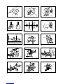
Switch action
CAUTION:
• Before plugging in the tool, always check to see
that the switch trigger actuates properly and
returns to the "OFF" position when released.
• When not using the tool, remove the lock-off
button and store it in a secure place. This prevents
unauthorized operation.
• Do not pull the switch trigger hard without pressing
in the lock-off button. This can cause switch
breakage.
For European countries
Fig.15
To prevent the switch trigger from being accidentally
pulled, a lock-off button is provided. To start the tool,
push the lever to the left, press in the lock-off button and
then pull the switch trigger. Release the switch trigger to
stop.
For all countries other than European countries
Fig.16
To prevent the switch trigger from being accidentally
pulled, a lock-off button is provided. To start the tool,
press in the lock-off button and pull the switch trigger.
Release the switch trigger to stop.
WARNING:
• NEVER use tool without a fully operative switch
trigger. Any tool with an inoperative switch is
HIGHLY DANGEROUS and must be repaired
before further usage.
• For your safety, this tool is equipped with a lock-off
button which prevents the tool from unintended
starting. NEVER use the tool if it runs when you
simply pull the switch trigger without pressing the
lock-off button. Return tool to a Makita service
center for proper repairs BEFORE further usage.
• NEVER tape down or defeat purpose and function
of lock-off button.
ASSEMBLY
CAUTION:
• Always be sure that the tool is switched off and
unplugged before carrying out any work on the
tool.
Installing or removing saw blade
CAUTION:
• Always be sure that the tool is switched off and
unplugged before installing or removing the blade.
• Use only the Makita socket wrench provided to
install or remove the blade. Failure to do so may
result in overtightening or insufficient tightening of
the hex bolt. This could cause an injury.
Lock the handle in the raised position by pushing in the
stopper pin.
To remove the blade, use the socket wrench to loosen the
hex bolt holding the center cover by turning it
counterclockwise. Raise the blade guard and center cover.
Fig.17
Press the shaft lock to lock the spindle and use the
socket wrench to loosen the hex bolt clockwise. Then
remove the hex bolt, outer flange and blade.
Fig.18
To install the blade, mount it carefully onto the spindle,
making sure that the direction of the arrow on the surface
of the blade matches the direction of the arrow on the
blade case. Install the outer flange and hex bolt, and then
use the socket wrench to tighten the hex bolt (left-handed)
securely counterclockwise while pressing the shaft lock.
Fig.19
CAUTION:
For all countries other than European countries
Fig.20
CAUTION:
• The silver ring 25.4 mm in outer diameter is
factory-installed onto the spindle. The black ring
25 mm in outer diameter is included as standard
equipment. Before mounting the blade onto the
spindle, always be sure that the correct ring for the
arbor hole of the blade you intend to use is
installed onto the spindle.
For European countries
• The ring 30 mm in outer diameter is factory-
installed between the inner and outer flanges.
Install the outer flange and hex bolt, and then use the
socket wrench to tighten the hex bolt (left-handed)
securely counterclockwise while pressing the shaft lock.
Return the blade guard and center cover to its original
position. Then tighten the hex bolt clockwise to secure
the center cover. Lower the handle to make sure that
the blade guard moves properly. Make sure shaft lock
has released spindle before making cut.
Dust bag
Fig.21
The use of the dust bag makes cutting operations clean
and dust collection easy. To attach the dust bag, fit it
onto the dust nozzle.
When the dust bag is about half full, remove the dust
bag from the tool and pull the fastener out. Empty the
dust bag of its contents, tapping it lightly so as to
remove particles adhering to the insides which might
hamper further collection.
NOTE:
If you connect a Makita vacuum cleaner to your saw,
more efficient and cleaner operations can be performed.

11
Securing workpiece
WARNING:
• It is extremely important to always secure the
workpiece properly and tightly with the vise.
Failure to do so can cause the tool to be damaged
and/or the workpiece to be destroyed. PERSONAL
INJURY MAY ALSO RESULT. Also, after a cutting
operation, DO NOT raise the blade until the blade
has come to a complete stop.
CAUTION:
• When cutting long workpieces, use supports that
are as high as the top surface level of the turn
base. Do not rely solely on the vertical vise and/or
horizontal vise to secure the workpiece.
Thin material tends to sag. Support workpiece
over its entire length to avoid blade pinch and
possible KICKBACK.
Fig.22
Sub-fence
Fig.23
This tool is equipped with the sub-fence. It should be
positioned as shown in the figure.
CAUTION:
• When performing left bevel cuts, flip the fence
over to the left position as shown in the figure.
Otherwise, it will contact the blade or a part of the
tool, causing possible serious injury to the operator.
Fig.24
Vertical vise
Fig.25
The vertical vise can be installed in two positions on
either the left or right side of the guide fence or the
holder assembly (optional accessory). Insert the vise
rod into the hole in the guide fence or the holder
assembly and tighten the screw to secure the vise rod.
Position the vise arm according to the thickness and
shape of the workpiece and secure the vise arm by
tightening the screw. If the screw to secure the vise arm
contacts the guide fence, install the screw on the
opposite side of vise arm. Make sure that no part of the
tool contacts the vise when lowering the handle all the
way. If some part contacts the vise, re-position the vise.
Press the workpiece flat against the guide fence and the
turn base. Position the workpiece at the desired cutting
position and secure it firmly by tightening the vise knob.
CAUTION:
• The workpiece must be secured firmly against the
turn base and guide fence with the vise during all
operations.
Horizontal vise (optional accessory)
Fig.26
The horizontal vise can be installed on either the left or right
side of the base. When performing 15° or greater miter cuts,
install the horizontal vise on the side opposite the direction
in which the turn base is to be turned. By turning the vise
knob counterclockwise, the screw is released and the vise
shaft can be moved rapidly in and out. By turning the vise
knob clockwise, the screw remains secured. To grip the
workpiece, turn the vise knob gently clockwise until the
projection reaches its topmost position, then fasten securely.
If the vise knob is forced in or pulled out while being turned
clockwise, the projection may stop at an angle. In this case,
turn the vise knob back counterclockwise until the screw is
released, before turning again gently clockwise.
The maximum width of the workpiece which can be
secured by the horizontal vise is 130 mm.
CAUTION:
• Grip the workpiece only when the projection is at
the topmost position. Failure to do so may result in
insufficient securing of the workpiece. This could
cause the workpiece to be thrown, cause damage
to the blade or cause the loss of control, which can
result in PERSONAL INJURY.
Holders and holder assembly
(optional accessories)
Fig.27
The holders and the holder assembly can be installed
on either side as a convenient means of supporting
workpieces horizontally. Install them as shown in the
figure. Then tighten the screws firmly to secure the
holders and the holder assembly.
When cutting long workpieces, use the holder-rod
assembly (optional accessory). It consists of two holder
assemblies and two rods 12.
Fig.28
CAUTION:
• Always support long workpieces level with the top
surface of the turn base for accurate cuts and to
prevent dangerous loss of control of the tool.
OPERATION
CAUTION:
• Before use, be sure to release the handle from the
lowered position by pulling the stopper pin.
• Make sure the blade is not contacting the
workpiece, etc. before the switch is turned on.
• Do not apply excessive pressure on the handle
when cutting. Too much force may result in
overload of the motor and/or decreased cutting
efficiency. Push down handle with only as much
force as is necessary for smooth cutting and
without significant decrease in blade speed.

12
• Gently press down the handle to perform the cut. If
the handle is pressed down with force or if lateral
force is applied, the blade will vibrate and leave a
mark (saw mark) in the workpiece and the
precision of the cut will be impaired.
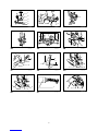
1. Press cutting
Fig.29
Secure the workpiece with the vise. Switch on the
tool without the blade making any contact and wait
until the blade attains full speed before lowering.
Then gently lower the handle to the fully lowered
position to cut the workpiece. When the cut is
completed, switch off the tool and WAIT UNTIL
THE BLADE HAS COME TO A COMPLETE STOP
before returning the blade to its fully elevated
position.
2. Miter cutting
Refer to the previously covered "Adjusting the
miter angle".
3. Bevel cut
Fig.30
Loosen the lever and tilt the saw blade to set the
bevel angle (Refer to the previously covered
"Adjusting the bevel angle"). Be sure to retighten
the lever firmly to secure the selected bevel angle
safely. Secure the workpiece with a vise. Switch
on the tool without the blade making any contact
and wait until the blade attains full speed. Then
gently lower the handle to the fully lowered
position while applying pressure in parallel with the
blade. When the cut is completed, switch off the
tool and WAIT UNTIL THE BLADE HAS COME TO
A COMPLETE STOP before returning the blade to
its fully elevated position.
CAUTION:
• Always be sure that the blade will move down to
bevel direction during a bevel cut. Keep hands out
of path of saw blade.
• During a bevel cut, it may create a condition
whereby the piece cut off will come to rest against
the side of the blade. If the blade is raised while
the blade is still rotating, this piece may be caught
by the blade, causing fragments to be scattered
which is dangerous. The blade should be raised
ONLY after the blade has come to a complete stop.
• When pressing the handle down, apply pressure
parallel to the blade. If the pressure is not parallel
to the blade during a cut, the angle of the blade
might be shifted and the precision of the cut will be
impaired.
• Always set the sub-fence to the left position when
performing left bevel cuts.
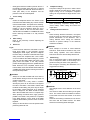
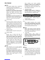
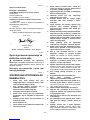
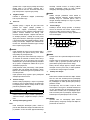
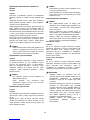
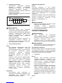
4. Compound cutting
Compound cutting is the process in which a bevel
angle is made at the same time in which a miter
angle is being cut on a workpiece. Compound
cutting can be performed at angle shown in the
table.
Miter angle
Bevel angle
Left and Right 0 - 45
45
006366
When performing compound cutting, refer to
"Press cutting", "Miter cutting" and "Bevel cut"
explanations.
5. Cutting aluminum extrusion
Fig.31
When securing aluminum extrusions, use spacer
blocks or pieces of scrap as shown in the figure to
prevent deformation of the aluminum. Use a
cutting lubricant when cutting the aluminum
extrusion to prevent build-up of the aluminum
material on the blade.
CAUTION:
• Never attempt to cut thick or round aluminum
extrusions. Thick aluminum extrusions may come
loose during operation and round aluminum
extrusions cannot be secured firmly with this tool.
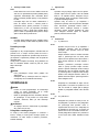
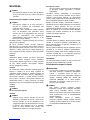
6. Wood facing
Use of wood facing helps to assure splinter-free
cuts in workpieces. Attach a wood facing to the
guide fence using the holes in the guide fence.
See the figure concerning the dimensions for a
suggested wood facing.
Over 10mm (3/8") Over 460mm (18-1/8")
11
90mm
(3-9/16")
25mm
(1")
90mm
(3-9/16")
107mm
(4-7/32")
90mm
(3-9/16")
107mm
(4-7/32")
001790
CAUTION:
• Use straight wood of even thickness as the wood
facing.
• Use screws to attach the wood facing to the guide
fence. The screws should be installed so that the
screw heads are below the surface of the wood
facing.
• When the wood facing is attached, do not turn the
turn base with the handle lowered. The blade
and/or the wood facing will be damaged.
1. Hole

13
7. Cutting repetitive lengths
Fig.32
When cutting several pieces of stock to the same
length, ranging from 240 mm to 400 mm, use of
the set plate (optional accessory) will facilitate
more efficient operation. Install the set plate on the
holder (optional accessory) as shown in the figure.
Align the cutting line on your workpiece with either
the left or right side of the groove in the kerf board,
and while holding the workpiece from moving,
move the set plate flush against the end of the
workpiece. Then secure the set plate with the
screw. When the set plate is not used, loosen the
screw and turn the set plate out of the way.
NOTE:
• Use of the holder-rod assembly (optional
accessory) allows cutting repetitive lengths up to
2,200 mm approximately.
Carrying tool
Fig.33
Make sure that the tool is unplugged. Secure the blade
at 0° bevel angle and the turn base at right miter angle
fully. Lower the handle fully and lock it in the lowered
position by pushing in the stopper pin.
Carry the tool by carrying grip as shown in the figure. If
you remove the holders, dust bag, etc., you can carry
the tool more easily.
Fig.34
CAUTION:
• Always secure all moving portions before carrying
the tool.
• Stopper pin is for carrying and storage purposes
only and not for any cutting operations.
MAINTENANCE
CAUTION:
• Always be sure that the tool is switched off and
unplugged before attempting to perform inspection
or maintenance.
• Never use gasoline, benzine, thinner, alcohol or
the like. Discoloration, deformation or cracks may
result.
WARNING:
• Always be sure that the blade is sharp and clean
for the best and safest performance.
Adjusting the cutting angle
This tool is carefully adjusted and aligned at the factory,
but rough handling may have affected the alignment. If
your tool is not aligned properly, perform the following:
1. Miter angle
Fig.35
Loosen the grip which secures the turn base. Turn
the turn base so that the pointer points to 0° on the
miter scale. Tighten the grip and loosen the hex
bolts securing the guide fence using the socket
wrench.
Lower the handle fully and lock it in the lowered
position by pushing in the stopper pin. Square the
side of the blade with the face of the guide fence
using a triangular rule, try-square, etc. Then
securely tighten the hex bolts on the guide fence
in the order from the right side.
Fig.36
2. Bevel angle
(1) 0° bevel angle
Fig.37
Lower the handle fully and lock it in the
lowered position by pushing in the stopper
pin. Loosen the lever at the rear of the tool.
Loosen the hex nut and turn the 0° bevel
angle adjusting bolt on the right side of the
turn base two or three revolutions clockwise
to tilt the blade to the right.
Carefully square the side of the blade with
the top surface of the turn base using the
triangular rule, try-square, etc. by turning the
0° bevel angle adjusting bolt
counterclockwise. Then tighten the hex nut to
secure the 0° bevel angle adjusting bolt and
tighten the lever securely.
Fig.38
Make sure that the pointer on the turn base
point to 0° on the bevel scale on the arm. If it
does not point to 0°, loosen the screw which
secures the pointer and adjust the pointer so
that it will point to 0°.
Fig.39
(2) 45° bevel angle
Fig.40
Adjust the 45° bevel angle only after
performing 0° bevel angle adjustment. To
adjust left 45° bevel angle, loosen the lever
and tilt the blade to the left fully. Make sure
that the pointer on the arm points to 45° on
the bevel scale on the arm. If the pointer
does not point to 45°, turn the 45° bevel
angle adjusting bolt on the left side of the
arm until the pointer points to 45°.
Replacing carbon brushes
Fig.41
Remove and check the carbon brushes regularly.
Replace when they wear down to the limit mark. Keep
the carbon brushes clean and free to slip in the holders.

14
Both carbon brushes should be replaced at the same
time. Use only identical carbon brushes.
Use a screwdriver to remove the brush holder caps.
Take out the worn carbon brushes, insert the new ones
and secure the brush holder caps.
Fig.42
After use
• After use, wipe off chips and dust adhering to the
tool with a cloth or the like. Keep the blade guard
clean according to the directions in the previously
covered section titled "Blade guard". Lubricate the
sliding portions with machine oil to prevent rust.
To maintain product SAFETY and RELIABILITY, repairs,
any other maintenance or adjustment should be
performed by Makita Authorized Service Centers,
always using Makita replacement parts.
OPTIONAL ACCESSORIES
CAUTION:
• These accessories or attachments are
recommended for use with your Makita tool
specified in this manual. The use of any other
accessories or attachments might present a risk of
injury to persons. Only use accessory or
attachment for its stated purpose.
If you need any assistance for more details regarding
these accessories, ask your local Makita Service Center.
• Steel & Carbide-tipped saw blades
• Auxiliary plate
• Vise assembly (Horizontal vise)
• Vertical vise
• Socket wrench 13
• Holder set
• Holder assembly
• Holder rod assembly
• Set plate
• Dust bag
• Triangular rule
• Lock-off button (2 pcs.)
NOTE:
• Some items in the list may be included in the tool
package as standard accessories. They may differ
from country to country.

15
SLOVENŠČINA (izvirna navodila)
Razlaga splošnega pogleda
1-1. Dodatna plošča
1-2. Šestrobi vijak
1-3. Osnovna plošča
2-1. Dodatna plošča
2-2. Osnovna plošča
2-3. Šestrobi vijak
2-4. Matica
3-1. Držalo
4-1. Držalo
4-2. Nastavljalni gumb
4-3. Vijak
5-1. Ustavljalni zatič
6-1. Vijak
7-1. Varovalo rezila
8-1. Varovalo rezila
9-1. Zarezna plošča
9-2. Vrtljiva osnovna plošča
10-1. Nasadni ključ
10-2. Nastavljalni vijak
11-1. Zgornja površina vrtljive osnovne
plošče
11-2. Robovi rezila
11-3. Vodilni prislon
12-1. Kazalec
12-2. Zaklepna ročica
12-3. Ročaj
12-4. Zajeralna lestvica
13-1. Ročica
14-1. Ročica
14-2. Lestvica za poševni kot
14-3. Kazalec
15-1. Ročica
15-2. Sprostilni gumb
16-1. Sprostilni gumb
16-2. Sprožilno stikalo
17-1. Središčni pokrov
17-2. Nasadni ključ
17-3. Šestrobi vijak
17-4. Varovalo rezila
18-1. Nasadni ključ
18-2. Zapora vretena
19-1. Ohišje rezila
19-2. Puščica
19-3. Rezilo žage
19-4. Puščica
20-1. Vreteno
20-2. Prirobnica
20-3. Rezilo žage
20-4. Prirobnica
20-5. Šestrobi vijak
20-6. Obroč
21-1. Sesalna šoba
21-2. Vrečka za prah
21-3. Pritrjevalnik
22-1. Opora
22-2. Vrtljiva osnovna plošča
23-1. Pomožno vodilo
24-1. Pomožno vodilo
25-1. Drog primeža
25-2. Vijak
25-3. Gumb primeža
25-4. Ročica primeža
25-5. Vodilni prislon
25-6. Sklop držala
25-7. Držalo
26-1. Gumb primeža
26-2. Izbočeni del
26-3. Vreteno primeža
26-4. Osnovna plošča
27-1. Sklop držala
27-2. Držalo
28-1. Sklop držala
28-2. Drog 12
31-1. Primež
31-2. Distančni blok
31-3. Vodilni prislon
31-4. Aluminijasti profil
31-5. Distančni blok
32-1. Fiksna plošča
32-2. Držalo
32-3. Vijak
33-1. Ustavljalni zatič
35-1. Šestrobi vijak
36-1. Trikotno merilo
36-2. Ročaj
36-3. Vodilni prislon
37-1. Roka
37-2. Ročica
37-3. 0 ゚ prilagoditveni vijak
37-4. Šestroba matica
38-1. Trikotno merilo
38-2. Rezilo žage
38-3. Zgornja površina vrtljive osnovne
plošče
39-1. Roka
39-2. Lestvica za poševni kot
39-3. Kazalec
39-4. Vrtljiva osnovna plošča
40-1. Ročica
40-2. Roka
40-3. Kazalec
40-4. 45 ゚ prilagoditveni vijak za
poševni kot
41-1. Meja obrabljenosti
42-1. Izvijač
42-2. Pokrov krtačke
TEHNIČNI PODATKI
Model LS1040 / LS1040S
Premer rezila 255 mm - 260 mm
Debelina ohišja rezila 1,6 mm - 2,4 mm
Premer luknje
Za vse ostale neevropske države 25,4 mm in 25 mm
Za evropske države 30 mm
Največja zmogljivost rezanja (V x Š) z rezilom premera 260 mm
Zajeralni kot
Poševni kot 0° 45° (levo in desno)
93 mm x 95 mm 93 mm x 67 mm
0° 69 mm x 135 mm 69 mm x 95 mm
53 mm x 95 mm 49 mm x 67 mm
45° (levo) 35 mm x 135 mm 35 mm x 94 mm

16
Hitrost brez obremenitve (min-1) 4.600
Mere (D x Š x V) 530 mm x 476 mm x 532 mm
Neto teža 12,4 kg
Varnostni razred /II
• Zaradi našega nenehnega programa raziskav in razvoja si pridržujemo pravico do spremembe tehničnih podatkov brez obvestila.
• Tehnični podatki se lahko razlikujejo od države do države.
• Teža je v skladu z EPTA-postopkom 01/2003
END217-5
Simboli
Naslednji simboli se uporabljajo v povezavi s strojem.
Pred uporabo proizvoda se obvezno seznanite z
njihovim pomenom.
・ Preberite navodila za uporabo.
・ DVOJNA IZOLACIJA
・ Da se izognete poškodbam zaradi
letečih ostankov, po rezu držite glavo
žage navzdol, dokler se rezilo
popolnoma ne ustavi.
・ Ne polagajte dlani ali prstov v bližino
rezila.
・ Za vašo varnost pred uporabo
odstranite ostružke, majhne delce itd. z
mize.
・ Pri izvajanju levih poševnih rezov
POMOŽNO VODILO vedno nastavite v
levi položaj. V nasprotnem primeru
lahko pride do hudih poškodb
upravljavca.
・ Vijak zavrtite v smeri urnega kazalca,
da ga odvijete.
・ Le za države EU
Električnega orodja ne odlagajte skupaj
z gospodinjskimi odpadki!
V skladu z Evropsko direktivo o
odpadni električni in elektronski opremi
in z njenim izvajanjem v skladu z
državno zakonodajo se mora električna
oprema, ki je prišla do konca svojega
življenjskega cikla, zbirati ločeno in se
vrniti v okoljsko združljivo ustanovo za
recikliranje.
ENE004-1
Namenska uporaba
Orodje je namenjeno za natančno ravno in poševno
rezanje lesa. Z ustreznimi rezili žage lahko žagate tudi
aluminij.
ENF002-2
Priključitev na električno omrežje
Napetost električnega omrežja se mora ujemati s
podatki na tipski ploščici. Stroj deluje samo z enofazno
izmenično napetostjo. Stroj je po evropskih smernicah
dvojno zaščitno izoliran, zato se ga lahko priključi tudi
na vtičnice brez ozemljitvenega voda.
Za model LS1040
ENF100-1
Za javna nizkonapetostna električna omrežja z
napetostjo med 220 V in 250 V.
Vklopi in izklopi električnih aparatov povzročajo nihanje
električne napetosti. Delovanje te naprave v neugodnih
omrežnih pogojih ima lahko neugodne učinke na
delovanje drugih priključenih naprav. Pri impedanci
omrežja do 0,29 Ohma je možno predpostaviti, da ne bo
negativnih učinkov. Omrežna vtičnica, na katero bo
priključena ta naprava, mora biti zaščitena z varovalko
ali s tokovnim zaščitnim stikalom s počasno
karakteristiko proženja.
ENG905-1
Hrup
Tipični, z A ocenjeni vrednosti hrupa glede na EN61029:
Raven zvočnega tlaka (LpA): 91 dB (A)
Raven zvočne moči (LWA): 101 dB (A)
Odstopanje (K): 3 dB (A)
Uporabljajte zaščito za sluh
ENG900-1
Vibracije
Skupne vrednosti vibracij (vektorska vsota treh osi) po
EN61029:
Oddajanje tresljajev (ah): 2,5 m/s2 ali manj
Odstopanje (K): 1,5 m/s2
ENG901-1
• Navedena vrednost oddajanja vibracij je bila
izmerjena v skladu s standardnimi metodami
testiranja in se lahko uporablja za primerjavo
orodij.
• Navedena vrednost oddajanja vibracij se lahko
uporablja tudi pri predhodni oceni izpostavljenosti.
OPOZORILO:
• Oddajanje vibracij med dejansko uporabo
električnega orodja se lahko razlikuje od navedene
vrednosti oddajanja, odvisno od načina uporabe
orodja.
• Upravljavec mora za lastno zaščito poznati
varnostne ukrepe, ki temeljijo na oceni
izpostavljenosti v dejanskih pogojih uporabe
(upoštevajoč celoten delovni proces v trenutkih, ko
je orodje izključeno in ko deluje v prostem teku z
dodatkom časa sprožitve).

17
ENH003-15
Samo za evropske države
ES Izjava o skladnosti
Družba Makita izjavlja, da je/so naslednji stroj/-i:
Oznaka stroja:
Kombinirana zajeralna žaga s krožno žago
Št. modela / tip: LS1040,LS1040S
Je skladen z naslednjimi evropskimi direktivami:
2006/42/ES
Izdelan v skladu z naslednjim standardom ali
standardiziranimi dokumenti:
EN61029
Tehnična dokumentacija v skladu z direktivo
2006/42/ES je na voljo na:
Makita, Jan-Baptist Vinkstraat 2, 3070, Belgija
30. 6. 2014
000331
Yasushi Fukaya
Direktor
Makita, Jan-Baptist Vinkstraat 2, 3070, Belgija
GEA010-1
Splošna varnostna opozorila za
električno orodje
OPOZORILO Preberite vsa varnostna opozorila in
navodila.
Neupoštevanje opozoril in navodil lahko vodi do
električnega udara, požara, in/ali hudih telesnih poškodb.
Shranite vsa opozorila in navodila za
kasnejšo uporabo.
ENB034-10
VARNOSTNA OPOZORILA ZA
UPORABO ZAJERALNE ŽAGE
1. Ne približujte rok liniji reza rezila žage.
Izogibajte se stiku s katerim koli rezilom v
prostem teku. Še vedno lahko povzroči hude
telesne poškodbe.
2. Pred uporabo pozorno preglejte rezilo žage,
ali je razpokano ali deformirano.
Takoj zamenjajte poškodovana rezila.
3. Ko se zarezna plošča obrabi, jo zamenjajte.
4. Uporabljajte samo rezila žage, ki jih je določil
proizvajalec in ki ustrezajo standardu EN847-1.
5. Ne uporabljajte rezil žage, narejenih iz
hitroreznega jekla.
6. Uporabljajte zaščito za oči.
7. Nosite zaščito za sluh, da zmanjšate tveganje
izgube sluha.
8. Pri rokovanju z rezilom žage (rezila žage
morajo biti v držalu, če je to možno) in grobim
materialom nosite rokavice.
9. Med žaganjem priključite zajeralno žago na
napravo za zbiranje prahu.
10. Rezilo žage izberite v skladu z materialom, ki
ga boste rezali.
11. Ne uporabljajte žage za rezanje drugih
materialov razen za les, aluminij ali podobne
materiale.
12. Pred prenašanjem orodja vedno pritrdite vse
gibljive dele. Kadar dvigujete ali prenašate
orodje, ne uporabljajte ščitnika kot nosilni
ročaj.
13. Ne uporabljajte žage brez nameščenih
ščitnikov. Pred vsako uporabo preverite
ščitnik rezila, če se pravilno zapira. Ne
uporabljajte žage, če se ščitnik rezila ne
premika prosto in se ne zapira. Nikoli ne
zatikajte ali zavežite ščitnika rezila v odprtem
položaju.
14. Tla morajo biti brez razsutega materiala, npr.
odstružkov in odrezkov.
15. Uporabljajte le rezila žage, ki so označena z
največjo hitrostjo, ki je enaka ali višja od
hitrosti brez obremenitve, označene na orodju.
16. Če je orodje opremljeno z laserjem ali LED
lučko, ne zamenjajte laserja ali LED lučke z
drugo vrsto. Glede popravila vprašajte v
pooblaščenem servisnem centru.
17.
Nikoli ne odstranite odrezanih kosov
obdelovanca iz rezalnega območja, medtem ko
orodje deluje z nezavarovanim rezilom žage.
18. Ne izvajajte nobenega dela prostoročno.
Obdelovanca morate pri vseh delih trdno pritrditi
ob vrtljivo osnovno ploščo in vodilni prislon s
primežem. Za pritrditev obdelovanca nikoli ne
uporabljajte roke.
19. Zagotovite, da je pred vsakim rezom orodje
stabilno.
20. Po potrebi pritrdite orodje na delovno mizo.
21. Dolge obdelovance podprite z zadostnimi
dodatnimi podporami.
22. Nikoli ne poskušajte rezati tako majhnih
obdelovancev, ki jih ne morete pritrditi s
primežem. Nepravilno pritrjeni obdelovanci lahko
povzročijo povratni udarec in hude telesne
poškodbe.
23. Nikoli ne segajte okrog rezila žage.
24. Preden premaknete obdelovanca ali
spreminjate nastavitve, izklopite orodje in
počakajte, da se rezilo žage ustavi.
25. Pred menjavo rezila ali servisom izklopite
orodje.
26. Ustavljalni zatič, ki pritrjuje glavo rezalnika, je
namenjen samo za nošnjo in shranjevanje in
ne za kakršno koli rezanje.
27. Orodja ne uporabljajte v prisotnosti vnetljivih
tekočin ali plinov. Električno delovanje orodja
lahko povzroči eksplozijo in požar, če je
izpostavljeno vnetljivim tekočinam ali plinom.

18
28. Uporabljajte samo prirobnice, ki jih posebej za
vaše orodje priporoča proizvajalec.
29. Pazite, da ne poškodujete vretena, prirobnic
(zlasti na delu, kjer se stika z orodjem) ali
vijaka. Poškodba teh delov lahko povzroči
zlom rezila.
30. Zagotovite, da je vrtljiva osnovna plošča
pravilno pritrjena, da se med delovanjem ne
bo premikala.
31. Za vašo varnost pred uporabo odstranite
ostružke, majhne delce itd. z mize.
32. Izogibajte se rezanju žebljev. Pred delom
poiščite in odstranite vse žeblje iz
obdelovanca.
33. Preden vklopite stikalo, se prepričajte, ali je
blokada osi sproščena.
34. Prepričajte se, ali se rezilo v najnižjem
položaju ne dotika vrtljive osnovne plošče.
35.
Trdno držite ročaj. Zavedajte se, da se žaga med
zagonom rahlo premika gor in dol in ustavlja.
36. Preden vklopite stikalo, se prepričajte, ali se
rezilo ne dotika obdelovanca.
37. Orodje naj nekaj časa deluje, preden ga
uporabite na dejanskem obdelovancu. Pazite
na tresljaje ali majanje, ki bi lahko nakazovali
slabo namestitev ali slabo uravnoteženo rezilo.
38. Pred rezanjem počakajte, da rezilo doseže
polno hitrost.
39. Če opazite kaj neobičajnega, takoj prenehajte
z uporabo.
40. Ne poskušajte zapahniti sprožilnika v
vklopljenem položaju.
41. Vedno bodite pozorni, zlasti med ponavljajočo
se, monotono uporabo. Naj vas navidezen
občutek varnosti ne uspava. Rezila ne
oproščajo.
42. Vedno uporabljajte pripomočke, priporočene v
teh navodilih. Uporaba neustreznih
pripomočkov, kot so abrazivne rezalne plošče,
lahko povzroči poškodbe.
43. Pri rezkanju bodite previdni.
44. Nekaj prahu, ki nastane med uporabo, vsebuje
kemikalije, za katere je znano, da povzročajo
raka, prirojene napake ali drugo škodo za
reprodukcijski sistem. Nekaj primerov teh
kemikalij je:
• svinec iz barv na osnovi svinca in,
• arzenik in krom iz kemično obdelanega
lesa.
Vaše tveganje zaradi izpostavljenosti je
različno in odvisno od tega, kako pogosto
opravljate tovrstno delo. Za zmanjšanje
izpostavljenosti kemikalijam: delajte v dobro
prezračenem območju in z odobreno
varnostno opremo, kot so tiste protiprašne
maske, ki so posebej zasnovane za filtriranje
mikroskopsko majhnih delcev.
45. Za zmanjšanje oddajanega hrupa zagotovite,
da je rezilo vedno ostro in čisto.
46. Upravljavec je zadostno usposobljen za
uporabo, prilagajanje in upravljanje stroja.
SHRANITE TA NAVODILA.
OPOZORILO:
NE dopustite si, da bi zaradi udobnejšega dela ali
poznavanja izdelka (pridobljenega z večkratno
uporabo) opustili striktno upoštevanje varnostnih
pravil pri uporabi stroja. ZLORABA ali
neupoštevanje varnostnih pravil v teh navodilih za
uporabo lahko povzroči hude telesne poškodbe.
NAMESTITEV
Nameščanje dodatne plošče
Sl.1
Sl.2
Namestite dodatno ploščo z uporabo zareze na osnovni
plošči orodja in jo pritrdite, tako da zategnete šestrobi
vijak.
Nameščanje držal
Sl.3
Sl.4
Namestite držala na obeh straneh osnovne plošče in jih
pritrdite z vijaki.
Prilagodite nastavljala, tako da se dotikajo površine tal.
OPOMBA:
V nekaterih državah držala morda niso opremljena z
nogicami.
Nameščanje mize
Med odpremo orodja je ročaj zapahnjen v spodnjem
položaju z ustavljalnim zatičem. Sprostite ustavljalni
zatič, tako da rahlo spustite ročaj in povlečete ustavljalni
zatič.
Sl.5
Orodje je treba priviti z dvema vijakoma na ravno in
stabilno podlago z uporabo izvrtin za vijake v osnovni
plošči orodja. To bo pomagalo preprečiti prevrnitev in
morebitne poškodbe.
Sl.6

19
OPIS DELOVANJA
POZOR:
• Pred vsako nastavitvijo ali pregledom nastavitev
stroja se prepričajte, da je le to izključeno in
ločeno od električnega omrežja.
Ščitnik rezila
Sl.7
Kadar spuščate ročaj, se ščitnik rezila samodejno
dvigne. Ščitnik rezila je pod vzmetno napetostjo, zato se
vrne v izhodiščni položaj, ko je rez dokončan in ročaj
dvignjen. NIKOLI NE ONESPOSOBITE ALI
ODSTRANITE ŠČITNIKA REZILA ALI VZMETI, KI JE
PRITRJENA NA ŠČITNIK.
V interesu vaše lastne varnosti vedno ohranite ščitnik
rezila v dobrem stanju. Vsakršno nepravilno delovanje
ščitnika rezila je treba takoj popraviti. Preverite, da se
prepričate, ali ima vzmet funkcijo za vrnitev ščitnika.
NIKOLI NE UPORABLJAJTE ORODJA, ČE JE
ŠČITNIK REZILA ALI VZMET POŠKODOVAN,
POKVARJEN ALI ODSTRANJEN. TO JE SKRAJNO
NEVARNO IN LAHKO PRIVEDE DO HUDIH TELESNIH
POŠKODB.
Če se prozorni ščitnik rezila umaže ali če se nanj prilepi
žagovina na takšen način, da rezilo ni več dobro vidno,
odklopite žago in previdno očistite ščitnik z vlažno krpo.
Za čiščenje plastičnega ščitnika ne uporabljajte topil ali
čistil na osnovi nafte.
Če je ščitnik rezila zelo onesnažen in je vidljivost skozi
ščitnik ovirana, uporabite priloženi nasadni ključ, da
odvijete šestrobi vijak, ki pritrjuje sredinski pokrov.
Odvijte šestrobi vijak, tako da ga zavrtite v nasprotni
smeri urnega kazalca, in dvignite ščitnik rezila ter
središčni pokrov. S ščitnikom rezila v takšnem položaju
je lahko čiščenje popolnejše in učinkovitejše. Ko je
čiščenje končano, izvedite zgornji postopek v obratnem
vrstnem redu in zategnite vijak. Ne odstranjujte vzmeti,
ki pritrjuje ščitnik rezila. Če se ščitnik zaradi staranja ali
izpostavljenosti UV-žarkom razbarva, stopite v stik s
servisom Makita in naročite nov ščitnik. NE
ONESPOSOBITE ALI ODSTRANJUJTE ŠČITNIKA.
Sl.8
Zarezna plošča
Sl.9
To orodje je opremljeno z zarezno ploščo v vrtljivi
osnovni plošči, da se zmanjša trganje na izhodni strani
reza. Če utor ni tovarniško zarezan v zarezno ploščo,
ga morate zarezati, preden začnete uporabljati orodje
za rezanje obdelovanca. Vklopite orodje in previdno
spustite rezilo, da zarežete utor v zarezno ploščo.
Ohranjanje največje učinkovitosti rezanja
Sl.10
Sl.11
To orodje je tovarniško nastavljeno, da zagotavlja
največjo učinkovitost rezanja za 260 mm rezilo žage.
Kadar nameščate novo rezilo, vedno preverite položaj
spodnjega omejila rezila in ga po potrebi prilagodite, kot
sledi:
Najprej orodje izključite iz električnega omrežja.
Popolnoma spustite ročaj. Uporabite nasadni ključ, da
zavrtite uravnalni vijak, dokler rob rezila ne seže malo
čez zgornjo površino vrtljive osnovne plošče na točki,
kjer se čelna stran vodilnega prislona stika z zgornjo
površino vrtljive osnovne plošče.
Orodje mora biti odklopljeno, nato zavrtite rezilo z roko,
medtem pa držite ročaj v spodnjem položaju, da se
prepričate, ali se rezilo morda ne dotika katerega koli
dela spodnje osnovne plošče. Ponastavite, če je
potrebno.
POZOR:
• Po namestitvi novega rezila se vedno prepričajte,
ali se rezilo morda ne dotika katerega dela
spodnje osnovne plošče, kadar je ročaj
popolnoma spuščen. To vedno storite, ko je orodje
odklopljeno.
Prilagoditev zajeralnega kota
Sl.12
Sprostite vrtljivi ročaj z vrtenjem v nasprotni smeri
urinega kazalca. Obrnite vrtljivo osnovno ploščo, pri tem
pa pritisnite zaklepno ročico navzdol. Ko ste premaknili
ročaj v položaj, kjer kazalka kaže želeni kot na zajeralni
lestvici, trdno zategnite ročaj v smeri urinega kazalca.
POZOR:
• Kadar vrtite vrtljivo osnovno ploščo, morate do
konca dvigniti ročaj.
•
Po spremembi zajeralnega kota vedno pritrdite vrtljivo
osnovno ploščo, tako da trdno zategnete ročaj.
Prilagoditev poševnega kota
Sl.13
Sl.14
Za prilagoditev poševnega zrahljajte ročico na zadnjem
delu orodja v nasprotni smeri urinega kazalca.
Potisnite ročaj v levo in nagnite rezilo žage, tako da
kazalka kaže proti želenemu kotu na lestvici za poševni
kot. Po nastavitvi trdno zategnite ročico v smeri urinega
kazalca, da pritrdite roko.
POZOR:
• Kadar nagibate rezilo žage, morate do konca
dvigniti ročaj.
• Po spremembi poševnega kota vedno pritrdite
roko, tako da trdno zategnete ročico v smeri
urinega kazalca.

20
Delovanje stikala
POZOR:
• Pred priključitvijo orodja na električno omrežje se
vedno prepričajte, da je stikalo brezhibno in da se
vrača v položaj za izklop (OFF), ko ga spustite.
• Kadar orodja ne uporabljate, odstranite gumb za
odklep in ga shranite na varnem mestu. To bo
preprečilo nepooblaščeno uporabo.
• Ne vlecite sprožilnega stikala močno, ne da bi pri
tem pritisnili sprostilni gumb. To lahko povzroči
zlom stikala.
Za evropske države
Sl.15
Za preprečevanje nenamerne sprožitve stikala je
nameščen sprostilni gumb. Za zagon orodja potisnite
ročico v levo, pritisnite sprostilni gumb, nato pa povlecite
sprožilno stikalo. Za izklop orodja spustite sprožilno stikalo.
Za vse ostale neevropske države
Sl.16
Za preprečevanje nenamerne sprožitve stikala je
nameščen sprostilni gumb. Za zagon orodja hkrati
pritisnite na sprostilni gumb in sprožilno stikalo. Za
izklop orodja spustite sprožilno stikalo.
OPOZORILO:
• NIKOLI ne uporabljajte orodja brez popolnoma
delujočega sprožilnega stikala. Vsako orodje z
nedelujočim stikalom je IZJEMNO NEVARNO in
ga je treba pred nadaljnjo uporabo popraviti.
• Za vašo varnost je to orodje opremljeno s
sprostilnim gumbom, ki preprečuje nenamerni
zagon orodja. NIKOLI ne uporabljajte orodja,
kadar začne delovati, če povlečete samo sprožilno
stikalo in pri tem ne pritisnete sprostilnega gumba.
PRED nadaljnjo uporabo vrnite orodje v servisni
center Makita v ustrezno popravilo.
• NIKOLI ne zalepite in ne onesposobite namena in
funkcije sprostilnega gumba.
MONTAŽA
POZOR:
•
Pred vsakim posegom v orodje se prepričajte, da je
le to izključeno in ločeno od električnega omrežja.
Namestitev ali odstranitev rezila žage
POZOR:
• Pred vsako nastavitvijo ali odstranjevanjem rezila
se prepričajte, ali je le ta izključen in ločen od
električnega omrežja.
• Za namestitev ali odstranjevanje rezila uporabite
samo priloženi nasadni ključ Makita. V
nasprotnem primeru je lahko posledica čezmerno
ali nezadostno privitje šestrobnega vijaka. To
lahko povzroči poškodbe.
Zaklenite ročaj v dvignjenem položaju, tako da potisnete
ustavljalni zatič.
Če želite odstraniti rezilo, uporabite nasadni ključ, da
odvijete šestrobni vijak, pri tem pa držite sredinski
pokrov in ga obrnete v nasprotni smeri urinega kazalca.
Dvignite ščitnik rezila in sredinski pokrov.
Sl.17
Pritisnite blokado osi, da zaklenete vreteno in uporabite
nasadni ključ, da odvijete šestrobni vijak v smeri urinega
kazalca. Nato odstranite šestrobi vijak, zunanjo
prirobnico in rezilo.
Sl.18
Previdno namestite rezilo na vreteno, pri tem pa se
prepričajte, ali se smer puščice na površini rezila ujema
s smerjo puščice na ohišju rezila. Namestite zunanjo
prirobnico in šestrobi vijak, nato pa uporabite nasadni
ključ, da trdno zategnete šestrobi vijak (levi) v nasprotni
smeri urinega kazalca, medtem ko pritiskate zaporo
vretena.
Sl.19
POZOR:
Za vse ostale neevropske države
Sl.20
POZOR:
• Srebrni obroč z zunanjim premerom 25,4 mm je
tovarniško nameščen na vreteno. Črni obroč z
zunanjim premerom 25 mm je vključen kot
standardna oprema. Preden namestite rezilo na
vreteno, se vedno prepričajte, ali je na vreteno
nameščen pravi obroč za osno luknjo rezila, ki ga
nameravate uporabiti.
Za evropske države
• Obroč z zunanjim premerom 30 mm je tovarniško
nameščen med notranjo in zunanjo prirobnico.
Namestite zunanjo prirobnico in šestrobi vijak, nato
uporabite nasadni ključ, da trdno zategnete šestrobi
vijak (levi) v nasprotni smeri urnega kazalca, medtem ko
pritiskate zaporo vretena.
Znova namestite ščitnik rezila in središčni pokrov. Nato
zategnite šestrobi vijak v smeri urnega kazalca, da
pritrdite središčni pokrov. Spustite ročaj, da se
prepričate, ali se ščitnik rezila pravilno premika. Preden
začnete rezati, se prepričajte, ali je zapora vretena
izpustila vreteno.
Vrečka za prah
Sl.21
Zaradi uporabe vrečke za prah je rezanje čisto, zbiranje
prahu pa enostavno. Kadar priključujete vrečko za prah,
jo namestite na sesalni nastavek.
Ko je vrečka za prah približno do polovice napolnjena,
jo odstranite z orodja in izvlecite pritrjevalnik. Vrečko za
prah izpraznite z rahlim udarjanjem, da se odstranijo
delci, ki so se sprijeli v notranjosti in bi lahko ovirali
nadaljnje zbiranje prahu.
Pagina se încarcă...
Pagina se încarcă...
Pagina se încarcă...
Pagina se încarcă...
Pagina se încarcă...
Pagina se încarcă...
Pagina se încarcă...
Pagina se încarcă...
Pagina se încarcă...
Pagina se încarcă...
Pagina se încarcă...
Pagina se încarcă...
Pagina se încarcă...
Pagina se încarcă...
Pagina se încarcă...
Pagina se încarcă...
Pagina se încarcă...
Pagina se încarcă...
Pagina se încarcă...
Pagina se încarcă...
Pagina se încarcă...
Pagina se încarcă...
Pagina se încarcă...
Pagina se încarcă...
Pagina se încarcă...
Pagina se încarcă...
Pagina se încarcă...
Pagina se încarcă...
Pagina se încarcă...
Pagina se încarcă...
Pagina se încarcă...
Pagina se încarcă...
Pagina se încarcă...
Pagina se încarcă...
Pagina se încarcă...
Pagina se încarcă...
Pagina se încarcă...
Pagina se încarcă...
Pagina se încarcă...
Pagina se încarcă...
Pagina se încarcă...
Pagina se încarcă...
Pagina se încarcă...
Pagina se încarcă...
Pagina se încarcă...
Pagina se încarcă...
Pagina se încarcă...
Pagina se încarcă...
Pagina se încarcă...
Pagina se încarcă...
Pagina se încarcă...
Pagina se încarcă...
Pagina se încarcă...
Pagina se încarcă...
Pagina se încarcă...
Pagina se încarcă...
Pagina se încarcă...
Pagina se încarcă...
Pagina se încarcă...
Pagina se încarcă...
Pagina se încarcă...
Pagina se încarcă...
Pagina se încarcă...
Pagina se încarcă...
Pagina se încarcă...
Pagina se încarcă...
Pagina se încarcă...
Pagina se încarcă...
Pagina se încarcă...
Pagina se încarcă...
Pagina se încarcă...
Pagina se încarcă...
Pagina se încarcă...
Pagina se încarcă...
Pagina se încarcă...
Pagina se încarcă...
Pagina se încarcă...
Pagina se încarcă...
Pagina se încarcă...
Pagina se încarcă...
Pagina se încarcă...
Pagina se încarcă...
Pagina se încarcă...
Pagina se încarcă...
Pagina se încarcă...
Pagina se încarcă...
Pagina se încarcă...
Pagina se încarcă...
Pagina se încarcă...
Pagina se încarcă...
Pagina se încarcă...
Pagina se încarcă...
-
 1
1
-
 2
2
-
 3
3
-
 4
4
-
 5
5
-
 6
6
-
 7
7
-
 8
8
-
 9
9
-
 10
10
-
 11
11
-
 12
12
-
 13
13
-
 14
14
-
 15
15
-
 16
16
-
 17
17
-
 18
18
-
 19
19
-
 20
20
-
 21
21
-
 22
22
-
 23
23
-
 24
24
-
 25
25
-
 26
26
-
 27
27
-
 28
28
-
 29
29
-
 30
30
-
 31
31
-
 32
32
-
 33
33
-
 34
34
-
 35
35
-
 36
36
-
 37
37
-
 38
38
-
 39
39
-
 40
40
-
 41
41
-
 42
42
-
 43
43
-
 44
44
-
 45
45
-
 46
46
-
 47
47
-
 48
48
-
 49
49
-
 50
50
-
 51
51
-
 52
52
-
 53
53
-
 54
54
-
 55
55
-
 56
56
-
 57
57
-
 58
58
-
 59
59
-
 60
60
-
 61
61
-
 62
62
-
 63
63
-
 64
64
-
 65
65
-
 66
66
-
 67
67
-
 68
68
-
 69
69
-
 70
70
-
 71
71
-
 72
72
-
 73
73
-
 74
74
-
 75
75
-
 76
76
-
 77
77
-
 78
78
-
 79
79
-
 80
80
-
 81
81
-
 82
82
-
 83
83
-
 84
84
-
 85
85
-
 86
86
-
 87
87
-
 88
88
-
 89
89
-
 90
90
-
 91
91
-
 92
92
-
 93
93
-
 94
94
-
 95
95
-
 96
96
-
 97
97
-
 98
98
-
 99
99
-
 100
100
-
 101
101
-
 102
102
-
 103
103
-
 104
104
-
 105
105
-
 106
106
-
 107
107
-
 108
108
-
 109
109
-
 110
110
-
 111
111
-
 112
112


Makita LS1040 Manual de utilizare
- Categorie
- Ferăstraie mitre
- Tip
- Manual de utilizare
- Acest manual este potrivit și pentru
Lucrări înrudite
-
Makita LS1016L Manual de utilizare
-
Makita DLS714 Manual de utilizare
-
Makita LH1040 Manual de utilizare
-
Makita LS1440 Manual de utilizare
-
Makita LF1000 Manual de utilizare
-
Makita LS1018 Manual de utilizare
-
Makita LS0714 Manual de utilizare
-
Makita SP6000 Manual de utilizare
-
-
Makita HS6101 Manual de utilizare