Whirlpool AKR 631 IX WP Program Chart
- Categorie
- Hote pentru aragaz
- Tip
- Program Chart
Acest manual este potrivit și pentru

5019 318
33160
AKR 631-666-812-966
AKR 943-948-952-995-996
KARTA INSTALACYJNA
Minimalna odległość od palników: 50 cm (od palników elektrycznych), 70 cm (od palników
gazowych, olejowych lub węglowych. Jeżeli w instrukcjach instalacji kuchenki gazowej
przewidziana została większa odległość w stosunku do odległości tutaj wskazanej, należy
ją zastosować. Podczas montażu należy przestrzegać kolejności numeracji (1
Ö
2
Ö
3
Ö
.....).
Nie podłączać urządzenia do zasilania, zanim nie zostanie zakończony całkowicie jego
montaż. Uwaga! Rura odprowadzająca dym i parę oraz kolanka nie są dostarczane i należy
je zakupić oddzielnie.
POPIS INSTALACE
Minimální vzdálenost od sporáků: 50 cm (elektrické sporáky), 70 cm (sporáky na plyn, naftu
nebo uhlí). Jestliže je v pokynech k instalaci plynového spotřebiče určena větší vzdálenost,
než je uvedená vzdálenost, je nutné ji dodržet. Při montáži sledujte číslování (1
Ö
2
Ö
3
Ö
.....).
Spotřebič připojte k elektrické síti až po úplném dokončení instalace. Pozor! Nasávací
trubka a pásky k upevnění nejsou součástí vybavení, musíte je zakoupit.
INŠTALAČNÁ SCHÉMA
Minimálna vzdialenost' od sporáka: 50 cm (elektrické sporáky), 70 cm (plynové sporáky,
sporáky na naftu alebo uhlie. Ak pokyny na inštaláciu plynovej varnej dosky určujú väčšiu
vzdialenost' ako je špecifikovaná, dodržiavajte ich. Pri montáži postupujte podľa číslic
(1
Ö
2
Ö
3
Ö
.....). Spotrebič nezapájajte do siete, kým nie je inštalácia úplne ukončená.
Upozornenie! Rúra na odvádzanie dymov a upevňovacie svorky sa nedodávajú, musíte ich
kúpit' samostatne.
ÜZEMBE HELYEZÉSI ÚTMUTATÓ
A tűzhelytől való minimális távolság: 50 cm (elektromos tűzhely), 70 cm (gáz-, olaj- vagy
széntüzelésű tűzhely). Amennyiben a gáztűzhely üzembe helyezési útmutatója nagyobb
távolságot ír elő, úgy azt kell betartani. A felszereléshez kövesse a számozást
(1
Ö
2
Ö
3
Ö
.....). A készüléket csak akkor szabad áram alá helyezni, ha a beüzemelés már
megtörtént. Figyelem! Az elvezető cső és a rögzítőpántok nem tartozékok, így azokat külön
meg kell vásárolni.
PL
CZ
SK
H
31833160.fm Page 1 Friday, April 1, 2005 6:48 PM

5019 318
33160
AKR 631-666-812-966
AKR 943-948-952-995-996
СХЕМА УСТАНОВКИ
Минимальное расстояние до конфорок: 50 см (электрические конфорки), 70 см
(газовые, керосиновые или угольные конфорки). Если инструкцией по установке
газовой плиты предусмотрено большее расстояние, то данное указание должно
быть выполнено. Последовательность действий при монтаже должна
соответствовать нумерации (1
Ö
2
Ö
3
Ö
.....). Не подключайте прибор к сети до
тех пор, пока его установка не будет полностью закончена. Внимание!
Выпускная труба и крепежные хомуты не входят в комплект поставки и
приобретаются отдельно.
КАРТА ЗА ИНСТАЛИРАНЕ
Минимално разстояние от печки: 50 см (електрически печки), 70 см (печки с газ,
нафта или въглища). Ако в инструкциите на устройството за готвене на газ е
указано по>голямо разстояние за тази спецификация, трябва да се изпълнява
това разстояние. За монтаж следвайте номерацията (1
Ö
2
Ö
3
Ö
.....). Не
включвайте захранването на уреда, докато инсталирането не е завършено
докрай. Внимание! Тръбата за отвеждане не е предоставена и трябва да се
закупи отделно.
FIȘA DE INSTALARE
Distanţa minimă de la arzătoare: 50 cm (arzătoare electrice), 70 cm (arzătoare pe bază de
gaze, petrol sau cărbune). Dacă instrucţiunile de instalare ale mașinii de gătit cu gaz
specifică o distanţă mai mare decât cea indicată, trebuie să ţineţi cont de ea. Pentru montaj
urmaţi numerotarea (1
Ö
2
Ö
3
Ö
.....). Nu branșaţi aparatul la curent până când nu terminaţi
definitiv operaţia de instalare. Atenţie! Tubul de evacuare și manșoanele de fixare nu fac
parte din dotare și trebuie să fie cumpărate separat.
INSTALLATION DATA SHEET
Minimum height above cooker: 50 cm (electric cookers), 70 cm (gas, gas oil or coal
cookers). If the installation instructions for a gas cooker specify a greater distance,
then this distance must be observed. To install, follow steps (1
Ö
2
Ö
3
Ö
.....). Do not
connect the hood to the electrical power supply until installation is completed.
Warning! The exhaust pipe and clamps are not supplied and must be bought
separately.
RUS
BG
RO
GB
31833160.fm Page 2 Friday, April 1, 2005 6:48 PM

5019 318
33160
AKR 631-666-812-966
AKR 943-948-952-995-996
a
a
a
31833160.fm Page 3 Friday, April 1, 2005 6:48 PM

5019 318
33160
AKR 631-666-812-966
AKR 943-948-952-995-996
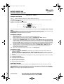
Remove the perimeter extraction panel (if relevant) and the grease filter/s.
Pre-assemble the steam deflector on the motor assembly (if relevant): (
a.
) fit the steam deflector to the rails of
the motor assembly (remove the two travel stop screws from the steam deflector if necessary), (
b.
) connect
up the control panel and the lamps, (
c.
) fix in place with the 14 screws (max).
1.
Mark a line on the wall right up to the ceiling, corresponding to the centre-line of the hood.
2.
Apply the drilling template to the wall: Align the vertical centre-line on the drilling template with the centre-
line drawn on the wall. The template's bottom edge represents the bottom edge of the hood.
3.
Place the mounting bracket over the drilling template so that it matches the outlined rectangle. Mark and
drill the two outside holes. Remove the drilling template. Insert two wall plugs in the holes and fix the hood
mounting bracket in place with two 5 x 45 mm screws.
4.
Hang the hood on the mounting bracket. Adjust gap (
5.
) and the horizontal alignment (
6.
) of the hood.
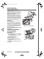
5.
Remove the hood from the bracket. Drill the holes (
9.
- Ø 8 mm - see step
7.
). Insert two wall plugs (
10.
).
6.
Apply the flue mounting bracket
G
to the wall against the ceiling. (Align the small slot in the bracket with
the centre-line drawn on the wall. See step
1.
Fix the bracket in place with two wall plugs (Ø 8 mm) and
2 screws
12
).
7.
Hang the hood on the bottom mounting bracket. (
14.
) Fix the hood to the wall with two 5 x 45 mm screws
(ABSOLUTELY NECESSARY). Plug the two holes if they are visible from the outside.
8.
Connect an exhaust pipe to the to the collar
B
, the fumes must be ducted to the outside (extractor version)
or towards the deflector (filter version). Fix the deflector
F
to the flue support bracket
G
with 4 screws
(2 screws only for
120 cm wide
model). If the collar (bayonet coupling) is not already fitted, insert it on
the deflector
F
and secure it with 1 screw.
9.
Make all necessary electrical connections.
10.
Apply the flues and fix them with 2 screws (
17a
) to the flue support
G
(
17b
).
11.
Slide the bottom section of the flue all the way over the extraction unit until it engages the seat above the
hood.
12.
(
120 cm wide
model only) fix the bottom section of the flue to the hood with 2 screws.
Re-fit the grease filter/s and, if a perimeter extraction panel is fitted, check for correct operation.
Important!
Only for model AKR 996: proceed with hob selection and manual calibration of the sensors. For
this purpose, read the paragraph on the next page “
Important - upon initial installation
”.
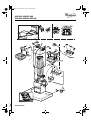
6
1.
Control panel.
2.
Grease filter.
3.
Halogen bulbs.
4.
Steam deflector.
5.
Telescopic flue.
6.
Perimeter extraction
panel (if fitted) and
release handle (
f3
).
7.
Sensors (only present
on some models).
INSTALLATION - ASSEMBLY INSTRUCTIONS
ROSK H RUS BGCZPL GB
31833160.fm Page 26 Friday, April 1, 2005 6:48 PM

5019 318
33160
AKR 631-666-812-966
AKR 943-948-952-995-996
Analogue control panel
Light : move the switch to the right or press the button to switch on.
Extraction speed : Move the switch to the right or press the next button to increase extraction speed
(or open the electric shutter ).
Digital control panel with sensors
The hood is fitted with a series of sensors which enable it to operate in 2 modes:
Automatic
mode
and
Manual
mode
.
Automatic mode:
the hood switches on automatically, depending on the ambient temperature (and heat) and
variations in this detected by the hood's sensors. See description of Button 3 function.
Manual mode:
the hood is switched on by the user.
Description of Buttons
1.
OFF/Stand by button:
When the hood is OFF, all the controls are disabled (all LEDs are off).
When on stand-by, the hood is ready to operate in “
Manual mode
”,
LED C
lights up.
2.
Light ON/OFF button: always works, even when the hood is OFF.
3.
ON/OFF button “
Automatic mode
”: press to activate this mode (
LED C
and
E
on) the hood switches
on automatically, selecting a suitable extraction speed in accordance with the ambient temperature (and
heat) and any variations in this detected by the hood's sensors.
Press again to revert to
“Manual mode”
: LED
E switches off, LED C remains on (stand by). The hood will continue to run for a few minutes after you have finished
cooking but can be turned off by pressing buttons 1 or 3. The automatic function (LED on) stops a few minutes after
the motor has been switched off. The automatic function must be switched on every time you start cooking.
4.
ON/OFF button for controlling intensive extraction speed in “
Manual mode
” (
LED D
switches on):
when selected, it operates for 5 minutes, after which time the hood automatically reverts to the
previously selected extraction speed.
5.-6.
Buttons for controlling extraction speed
1 - 2 - 3
in “
Manual mode
”.
Description of LEDs
A.
Carbon filter
saturation led indicator
: this led lights up to indicate that the carbon filter needs to be
cleaned or replaced.
Important: this indicator must be activated in order for the hood to work:
to activate it, press buttons
4
and
5
at the same time -
LED B
lights up first, followed by
LED A
to indicate that the led indicator is
working.
B.
Grease filter saturation led indicator: this led lights up to indicate that the grease filter needs to be cleaned.
C.
“Stand by” led indicator.
D.
Intensive speed led indicator.
E.
“Automatic mode” led indicator.
F.
Extraction speed 1 led indicator.
G.
Extraction speed 2 led indicator.
H.
Extraction speed 3 led indicator.
Reset filters indicator:
After cleaning or replacing the filters, with the hood on
Stand by
press Button
1
for more than 3 seconds.
Safety function:
this function is activated ONLY with the hood on stand-by, in the event of any SUDDEN,
VIOLENT increase in the temperature detected by the sensors, upon which the hood switches to “
Automatic
mode
” and, if necessary, selects a suitable extraction speed.
PRODUCT SHEET
ROSK H RUS BGCZPL GB
31833160.fm Page 27 Friday, April 1, 2005 6:48 PM

5019 318
33160
AKR 631-666-812-966
AKR 943-948-952-995-996
Important - upon initial installation:
Selecting the hob type:
to ensure accurate
“reading” by the sensors, the latter must be calibrated
to suit the type of hob as follows: with the hood OFF,
press buttons 3 and 4 at the same time until either
LED F
for gas hobs,
LED G
for induction hobs or
LED H
for electric hobs lights up.
Automatic and manual sensor calibration:
the
hood automatically “calibrates” sensor operation, but
under certain circumstances (e.g.: in the event of a
prolonged power failure or upon initial installation)
calibration can be carried out manually, with the hood
OFF, by pressing buttons
5
and
6
at the same time for
more than 3 seconds, otherwise you can wait until the
hood carries out calibration automatically.
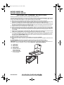
Maintenance
ALWAYS disconnect the hood from the mains before
performing maintenance.
Wash the
grease filter
and the
carbon filter
in a
dishwasher once a month, at the highest possible
temperature, using normal dishwasher detergent. It is
recommended to wash the filters on the their own.
After washing, reactivate
the carbon filter
by drying
it in the oven at 100 °C for 10 minutes. Fit a new
carbon filter every 3 years.
Remove the grease filters - Fig. 1:
push the spring
release handle backwards (
f1
) then remove the filter
downwards (
f2
).
Clean the perimeter extraction panel
(if provided) as often as the grease filter
, using a
cloth and a mild liquid detergent.
Never use abrasive substances.
Clean the sensor plate regularly.
Replacing bulbs
1.
Use a small screwdriver or any other suitable tool
to prise off (
m-Fig. 1
) the lamp cover (
p-Fig.1
).
2.
Remove the burnt-out bulb.
Use max 20 W halogen bulbs only, taking care not
to touch them with your hands.
3.
Close the lighting unit (snap-on).
Fitting the carbon filter:
1.
Remove the grease filter (
f1/f2 - Fig. 1
).
2.
Remove the filter holder by turning the knobs
(
g - Fig. 2
) through.
3.
Fit the carbon filter (
i - Fig. 2
) in the filter holder
(
h - Fig.2
).
Reverse the above procedure to re-fit the filter holder
and grease filter.
Fig. 2
f3
* Only present on some models
Fig. 1
ROSK H RUS BGCZPL GB
31833160.fm Page 28 Friday, April 1, 2005 6:48 PM
-
 1
1
-
 2
2
-
 3
3
-
 4
4
-
 5
5
-
 6
6


Whirlpool AKR 631 IX WP Program Chart
- Categorie
- Hote pentru aragaz
- Tip
- Program Chart
- Acest manual este potrivit și pentru
în alte limbi
- English: Whirlpool AKR 631 IX WP
- slovenčina: Whirlpool AKR 631 IX WP
Lucrări înrudite
-
Whirlpool AKR 802 IX Program Chart
-
Whirlpool AKR 995 IX Program Chart
-
-
-
-
-
-
Whirlpool AKR 420 AV-1 Manualul utilizatorului
-
-