

General information
© 2005 ‐ 2019 Renishaw plc. All rights reserved.
This document may not be copied or reproduced in whole or in part, or transferred to any other media or language, by any means, without
the prior written permission of Renishaw.
The publication of material within this document does not imply freedom from the patent rights of Renishaw plc.
Disclaimer
RENISHAW HAS MADE CONSIDERABLE EFFORTS TO ENSURE THE CONTENT OF THIS DOCUMENT IS CORRECT AT THE DATE OF
PUBLICATION BUT MAKES NO WARRANTIES OR REPRESENTATIONS REGARDING THE CONTENT. RENISHAW EXCLUDES LIABILITY,
HOWSOEVER ARISING, FOR ANY INACCURACIES IN THIS DOCUMENT.
Trademarks
RENISHAW, the probe symbol used in the RENISHAW logo and REVO are registered trademarks of Renishaw plc in the United Kingdom and
other countries. apply innovation and names and designations of other Renishaw products and technologies are trademarks of Renishaw
plc or its subsidiaries.
All brand names and product names used in this document are trade names, service marks, trademarks, or registered trademarks of their
respective owners.
All trademarks and trade names are acknowledged.
WEEE
The use of this symbol on Renishaw products and/or accompanying documentation indicates that the product should not be mixed with the
general household waste upon disposal. It is the responsibility of the end user to dispose of this product at a designated collection point for
waste electrical and electronic equipment (WEEE) to enable reuse or recycling. Correct disposal of this product will help save valuable
resources and prevent potential negative effects on the environment. For more information, please contact your local waste disposal service
or Renishaw distributor.
Warranty
Renishaw plc warrants its equipment for a limited period (as set out in our Standard Terms and Conditions of Sale) provided that it is installed
exactly as defined in associated Renishaw documentation.
Prior consent must be obtained from Renishaw if non-Renishaw equipment (e.g. interfaces and/or cabling) is to be used or substituted. Failure
to comply with this will invalidate the Renishaw warranty.
Claims under warranty must be made from authorised service centres only, which may be advised by the supplier or distributor.
SP25M user's guide
www.renishaw.com
Issued 10 2019
2

Care of equipment
Renishaw probes and associated systems are precision tools used for obtaining precise measurements and must therefore be treated with
care.
Changes to Renishaw products
Renishaw reserves the right to improve, change or modify its hardware or software without incurring any obligations to make changes to
Renishaw equipment previously sold.
Packaging
To aid end user recycling and disposal the materials used in the different components of the packaging are stated here:
Packaging component Material 94/62/EC code 94/62/EC number
Outer box Non-corrugated fibreboard PAP 21
Outer box Corrugated fibreboard PAP 20
Storage box Polypropylene PP 5
Packing foam Low density polyethylene LDPE 4
Patents
Features of the SP25M system and associated products, equipment and techniques are the subjects of one or more of the following patents
and patent applications:
EP1086352 JP4062515 US6772527
EP1368615 JP4726303 US6909983
EP1505362 JP5210536 US7146741
SP25M user's guide
www.renishaw.com
Issued 10 2019
3

Product compliance
EU declaration of conformity
Contact Renishaw plc or visit www.renishaw.com/EU for the full EU declaration.
EMC conformity
This equipment must be installed and used in accordance with this installation guide. This product is intended for industrial use only and
should not be used in a residential area or connected to a low voltage power supply network which supplies buildings used for residential
purposes.
FCC (USA only)
Information to user (47 CFR 15.105)
This equipment has been tested and found to comply with the limits for a Class A digital device, pursuant to Part 15 of the FCC rules. These
limits are designed to provide reasonable protection against harmful interference when the equipment is operated in a commercial
environment. This equipment generates, uses, and can radiate radio frequency energy and, if not installed and used in accordance with the
instruction manual, may cause harmful interference to radio communications. Operation of this equipment in a residential area is likely to
cause harmful interference, in which case you will be required to correct the interference at your own expense.
Information to user (47 CFR 15.21)
The user is cautioned that any changes or modifications not expressly approved by Renishaw plc or authorised representative could void the
user's authority to operate the equipment.
Equipment label (47 CFR 15.19)
This device complies with part 15 of the FCC Rules. Operation is subject to the following two conditions:
1. This device may not cause harmful interference.
2. This device must accept any interference received, including interference that may cause undesired operation.
SP25M user's guide
www.renishaw.com
Issued 10 2019
4

REACH regulation
Information required by Article 33﴾1﴿ of Regulation ﴾EC﴿ No. 1907/2006 ﴾“REACH”﴿ relating to products containing substances of very high
concern (SVHCs) is available at:
www.renishaw.com/REACH
China RoHS
Contact Renishaw plc or visit www.renishaw.com/ChinaRoHS for the full China RoHS tabulation.
SP25M user's guide
www.renishaw.com
Issued 10 2019
5

International safety instructions
BG ‐ ПРЕДУПРЕЖДЕНИЕ
Моля, обърнете на приложение 1 и прочетете инструкциите за безопасност на вашия собствен език, преди за разопаковате и
монтирате този продукт.
CZ ‐ VÝSTRAHA
Před rozbalením a instalací tohoto výrobku si přečtěte bezpečnostní pokyny ve vlastním jazyce uvedené v příloze 1.
DA - ADVARSEL
Læs sikkerhedsinstrukserne i Appendix 1 FØR udpakning og installation af dette produkt.
DE - WARNHINWEIS
Bevor Sie dieses Produkt auspacken und installieren, konsultieren Sie bitte Anhang 1 und lesen Sie die Sicherheitshinweise in Ihrer Sprache.
EL ‐ ΠΡΟΕΙΔΟΠΟΙΗΣΗ
Γυρίστε στο Κεφάλαιο 1 και διαβάστε τις οδηγίες ασφαλείας στη δική σας γλώσσα προτού ανοίξετε αυτό το προϊόν για να το
εγκαταστήσετε.
EN - WARNING
Before unpacking and installing this product, please consult Appendix 1 and read the safety instructions in your language.
ES - ADVERTENCIA
Consulte el apéndice 1 y lea las instrucciones de seguridad en su idioma antes de desempaquetar e instalar este producto.
ET - HOIATUS
Palun vaadake 1. lisa ning lugege enne selle toote lahtipakkimist ja paigaldamist ohutusjuhend läbi.
FI - VAROITUKSIA
Lue liitteessä 1 olevat omalla kielelläsi kirjoitetut turvaohjeet ennen tämän tuotteen pakkauksen avaamista ja asentamista.
FR - AVERTISSEMENT
Consulter l'annexe 1 et les instructions de sécurité dans votre propre langue avant de déballer et d'installer ce produit.
SP25M user's guide
www.renishaw.com
Issued 10 2019
6

GA - RABHADH
Téigh chuig aguisín 1 agus déan na treoracha sábháilteachta a léamh i do theanga féin le do thoil sula ndéantar an táirge seo a dhíphacáil
agus a shuiteáil.
HR - NAPOMENA
Prije nego što proizvod izvadite iz ambalaže i ugradite ga, otvorite Prilog 1 i pročitajte sigurnosne upute na svom jeziku.
HU – FIGYELMEZTETÉS
A termék kicsomagolása és telepítése előtt olvassa el az 1. számú függelékben található, az Ön anyanyelvén hozzáférhető biztonsági
utasításokat.
IT - AVVISO
Prima di aprire ed installare questo prodotto, leggere le istruzioni di sicurezza nella vostra lingua riportate nell'Appendice 1.
JA ‐ 警告
この製品を箱から取り出し設置する前に、付録 1 に記載された安全性に関する注意書きをお読みください。
LT – ĮSPĖJIMAS
Prieš išpakuodami ir įdiegdami produktą, turite grįžti prie 1 priedo ir perskaityti nurodymus dėl saugos savo kalba.
LV – BRĪDINĀJUMS
Pirms šī izstrādājuma izsaiņošanas un uzstādīšanas izskatiet 1. pielikumā sniegtās drošības instrukcijas savā valodā.
MT - TWISSIJA
Jekk jogħġbok mur f'appendiċi 1 u aqra l‐istruzzjonijiet tas‐sigurtà fil‐lingwa tiegħek qabel ma toħroġ dan il‐prodott mill‐ippakkjar u
tinstallah.
NL - WAARSCHUWING
Ga naar appendix 1 en lees de veiligheidsinstructies in uw eigen taal, voordat u dit product uitpakt en installeert.
PL ‐ OSTRZEŻENIE
Przed rozpakowaniem i zainstalowaniem tego produktu prosimy o zapoznanie się z Dodatkiem 1 i przeczytanie zaleceń dotyczących
bezpieczeństwa w danym języku.
PT ‐ ADVERTÊNCIA
Você deve retornar ao Anexo 1 e ler as instruções de segurança em seu idioma antes de desembalar e instalar este produto.
SP25M user's guide
www.renishaw.com
Issued 10 2019
7

RO - AVERTISMENT
Înainte de a desface ambalajul şi a instala acest produs, vă rugăm să căutaţi Anexa 1 şi să citiţi cu atenţie instrucţiunile de siguranță, în limba
română.
SK ‐ VÝSTRAHA
Pred rozbalením a inštaláciou tohto produktu si pozrite prílohu 1 a prečítajte si bezpečnostné pokyny vo vašom jazyku.
SL - OPOZORILO
Preden izdelek vzamete iz embalaže in ga vgradite, odprite Prilogo 1 in preberite varnostna navodila v svojem jeziku.
SV - VARNING
Gå till bilaga 1 och läs säkerhetsinstruktionerna på ditt eget språk innan du packar upp och installerar denna produkt.
TW ‐ 警告
在拆開和安裝本產品之前,請翻頁至附錄 1 閱讀母語的安全指示。
中文 — 警告
在拆包和安装本产品之前,请翻到附录1,阅读中文版安全说明。
SP25M user's guide
www.renishaw.com
Issued 10 2019
8

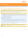
General safety recommendations
CAUTION: Before unpacking and installing the SP25M probe system, the user should carefully read the safety instructions below
and ensure that they are followed at all times by all operators using the probe system. Use of controls or adjustments, or
performance of procedures other than those specified herein may result in hazardous infra red radiation exposure.
Operators must be trained in the use and application of the SP25M probe system and accompanying products, in the context of the
machine it is fitted to, before being allowed to operate that machine.
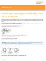
NOTE: References are made below to features indicated [†] [‡] [♦] on the illustrations shown below. Please ensure that you clearly
understand all safety instructions. Familiarisation with the SP25M system components, as shown in the following sections is
recommended:
System components overview
Schematic diagram of probe system components
Schematic diagram of FCR25 flexible change rack
Schematic diagram of FCR25 TC flexible change rack
The SP25M probe system has mechanical overtravel protection provided in the probe +Z axis, by a fixed bumpstop. The machine
control system must therefore be able to stop the motion of the machine, in this axis of the probe, before the bumpstop is reached.
If this is not the case, the user must wear eye protection during operation in case of stylus breakage.
Care should be taken to ensure that the optical windows ﴾indicated [♦]﴿, located on both body and module, do not become damaged as they
are made of glass and could cause injury.
CAUTION: Permanent magnets are used in some components of the SP25M system and associated products. It is important to
keep them away from items which may be affected by magnetic fields, e.g. data storage systems, pacemakers and watches etc.
SP25M user's guide
www.renishaw.com
Issued 10 2019
9

LED safety
The SP25M body contains embedded high power LED sources ﴾indicated [†]﴿ which emit invisible infra‐red radiation. These sources are
exposed when an SM25-# or TM25-20 module is not attached.
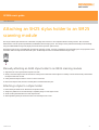
Removing the module breaks two sets of interlock switch contacts ﴾indicated [‡]﴿ to automatically switch off the LED power and assure user
safety.
At suitable intervals, the interlock contacts should be inspected and checked to ensure that they are clean and free from airborne
contamination such as dust, debris or swarf. In unlikely circumstances, such contamination could cause a short circuit of the pins and thus
increase the risk of sending power to the LEDs, without a module being attached. Never connect conducting objects to, or between, the
contacts. Follow the cleaning instructions in the Maintenance section.
Before inspecting, always remove the SP25M body from the probe head.
In the event of serious damage to, or a rupture of, any part of the SP25M body or scanning module outer casing, IMMEDIATELY disconnect
power source, remove and do not attempt to re-use the parts, and contact your supplier for advice.
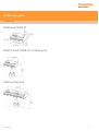
Safety illustrations
These diagrams show features, indicated [†] [‡] [♦] which are referred to within these safety recommendations.
SP25M probe body
End view showing kinematic joint to module
SP25M kinematic joint to module
SM25 scanning modules
End view showing kinematic joint to body
SP25M kinematic joint to body
SP25M user's guide
www.renishaw.com
Issued 10 2019
10

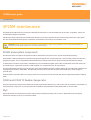
Introduction
NOTE: Before unpacking and installing the SP25M probe system, please read the safety information and ensure that they are
followed at all times during system installation and operation.
This document is intended to provide help and guidance during initial installation, integration and subsequent use of the of the SP25M probe
system. It is assumed that the system will be installed on a coordinate measuring machine using a controller system that has had full SP25M
system integration in the form of a dedicated Renishaw controller or an AC3 (ISA bus) analogue interface PC card.
SP25M is a compact and versatile probe system that provides both scanning capability for form measurement or reverse engineering and
touch-trigger probing for geometric size and position measurement.
The SP25M system provides highly accurate scanning measurement with stylus lengths from 20 mm to 400 mm as well as full TP20 touch-
trigger probe module compatibility to suit a range of applications.
The SP25M system uses the Renishaw autojoint to enable repeatable mounting to the PH10M PLUS, PH10MQ PLUS and PH6M probe heads.
Multiwired extension bar mounting of the SP25M system is also possible to extend the reach and enable more access to part features.
The range of SM25 scanning modules are designed to cover specific stylus length ranges whilst maintaining excellent accuracy performance.
The system can be readily expanded to further increase the scanning range, allow TP20 touch-trigger measurement or utilise an automatic
changer system.
SP25M user's guide
www.renishaw.com
Issued 10 2019
11

Design principles of the SP25M system
The SP25M design features an optical transducer sensor system which is located within the SP25M probe body. The design also features a
spring pivoting motion system which is located within the SM25 scanning modules.
Two infrared light emitting diodes (IREDs) mounted in the SP25M probe body project invisible infrared beams on to two mirrors mounted on
the pivoting motion structure within the SM25 scanning module. The mirrors reflect the beam back to the SP25M probe body where their
change in position is detected by two position sensitive devices (PSDs) when the stylus is deflected. The PSDs provide signal outputs in the
three probe axes; P, Q and R.
NOTE: The SP25M probe system does not have a fixed rate, gain or resolution and the P, Q and R probe axis outputs are non-linear
and non-orthogonal. These outputs are converted to X, Y and Z signals by the calibration routine. Renishaw offer support and
advice on scanning calibration algorithms suited to SP25M.
The SM25 scanning modules are designed to provide an optimised level of accuracy and contact force over a specified stylus range. This
minimises the reduction in performance seen in other types of scanning probes as the stylus length increases.
SP25M user's guide
www.renishaw.com
Issued 10 2019
12

System components overview
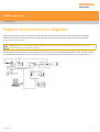
System overview
The modular design of the SP25M system enables the flexibility for optimum configuration by the user. Please refer to the schematic
diagrams showing the SP25M system components in the SP25M installation section of this document.
SP25M probe body
The SP25M probe body houses the optical transducer system and attaches to PH10M PLUS, PH10MQ PLUS or PH6M using a Renishaw
autojoint connection.
SM25 scanning modules
There are five scanning modules in the SM25 range which enable accurate scanning measurements at different stylus lengths. SM25-1,
SM25-2, SM25-3 and SM25-4 are recommended for use with linear stylus arrangements and SM25-5 is recommended for use with non-
linear and star stylus arrangements.
SH25 stylus holders
The range of SH25 stylus holders enable accurate scanning measurements with effective stylus lengths ranging from 20 mm to 400 mm.
SH25-1, SH25-2, SH25-3 and SH25-4 are recommended for use with linear stylus arrangements. SH25-2A, SH25-3A, SH25-4A and SH25-5
are recommended for use with non-linear and star stylus arrangements.
TM25-20 adaptor module
For rapid touch-trigger measurement, the TM25-20 adaptor module may be used which provides full compatibility with the whole range of
TP20 touch-trigger probe modules.
SP25M user's guide
www.renishaw.com
Issued 10 2019
13

FCR25 flexible change rack
Automated and repeatable changing of the SM25 scanning modules, SH25 stylus holders and TM25-20 is possible with FCR25. This triple
port system is designed for mounting on the Renishaw MRS rail system.
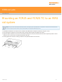
FCR25-L3 and FCR25-L6 leg mounted flexible change racks
These variants of the FCR25 flexible change rack and designed to be mounted to the bed of the CMM with the integrated leg assembly.
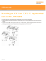
FCR25 TC change rack
The FCR25 TC provides automated and repeatable changing of SM25 scanning modules whilst keeping the ports at the same operating
temperature as the SP25M probe body. This ensures that there is no difference in temperature between the SP25M probe body and the
SM25 scanning modules eliminating thermal variation and providing optimum metrology.
AC3 analogue interface PCB card
An ISA bus card to enable integration of the SP25M system with a CMM manufacturer's own controller.
SP25M user's guide
www.renishaw.com
Issued 10 2019
14

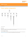
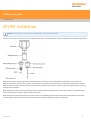
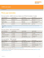
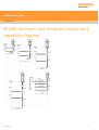
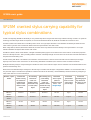
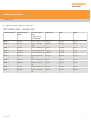
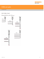
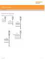
Probe system components
* Other variants exist
Scanning
The SM25 range of scanning modules are only compatible with the respective range of numbered stylus holders. Each scanning module is
optimised to provide reliable and accurate measurement at a range of working lengths.
Touch-trigger probing
The TM25-20 adaptor module provides touch-trigger probing capability by utilising the full range of TP20 probe modules. Please visit
www.renishaw.com/cmmguides for more information on the Renishaw TP20 touch-trigger probe system.
SP25M user's guide
www.renishaw.com
Issued 10 2019
15

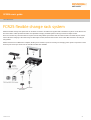
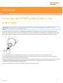
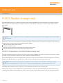
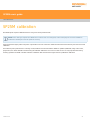
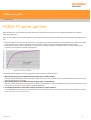
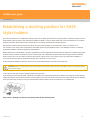
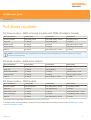
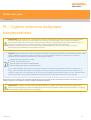
FCR25 flexible change rack system
FCR25 is a flexible change rack system that can be either mounted to an MRS rail or supplied with a standalone leg which can be fixed to the
bed of the CMM. FCR25 provides automatic and repeatable changing of SP25M system scanning modules and stylus holders.
There are a number of port inserts that are required to interchange SH25 stylus holders and also TP20 modules. The PA25-SH port insert is
used to allow the changing of the whole range of SH25 stylus holders, the PA25-20 should be used to allow TP20 modules to be changed
using FCR25.
FCR25 can be fixed to an MRS rail in multiples, allowing more numbers of ports for housing and changing probe system components. There
are three port and six port versions of the standalone FCR25 also available.
SP25M user's guide
www.renishaw.com
Issued 10 2019
16

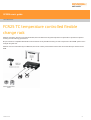
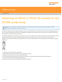
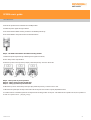
FCR25 TC temperature controlled flexible
change rack
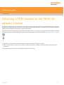
FCR25 TC is similar in function to the standard FCR25, the main difference being that temperature compensation is provided to optimise
scanning module metrology performance.
No port inserts are compatible with FCR25 TC which means that only the SM25 scanning module components of the SP25M system can be
changed using this rack.
FCR25 TC can be mounted directly to an MRS rail, there is also a three port standalone version that can be fixed directly to the bed on the
CMM.
SP25M user's guide
www.renishaw.com
Issued 10 2019
17

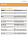
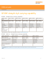
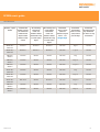
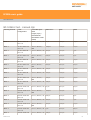
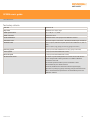
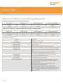
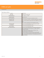
SP25M specification
Characteristic Requirements
Probe attributes Scanning with 3-axis measurement (X, Y, Z)
Touch-trigger probing using TP20 modules
Measurement range ±0.5 mm deflection in all directions in all orientations
Overtravel range
X, Y ±2 mm
+Z 1.7 mm
-Z 1.2 mm
Resolution Capable of <0.1 μm
Spring rate Nominally 0.6 N/mm - when using a module's shortest specified
stylus
Nominally 0.2 N/mm - when using a module's longest specified
stylus
Probe dimensions Ø25 mm × length dependant on module used
Weight
SP25M body 65 g (2.29 oz)
SM25-1 scanning module 35 g (1.23 oz) (including SH25-1 but excluding stylus)
SM25-2 scanning module 40 g (1.41 oz) (including SH25-2 but excluding stylus)
SM25-3 scanning module 49 g (1.73 oz) (including SH25-3 but excluding stylus)
SM25-4 scanning module 71 g (2.50 oz) (including SH25-4 but excluding stylus)
SM25-5 scanning module 45 g (1.59 oz) (including SH25-5 but excluding stylus)
TM25-20 adaptor module 40 g (1.41 oz) (including TP20 STD module, but excluding stylus)
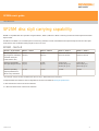
Effective stylus length range
(Always observe the specified stylus range for the scanning module
being used. Use Renishaw's M3 range of styli.)
SM25-1 + SH25-1 EWL 20 mm - 50 mm (0.79 in - 1.97 in) using 20 mm - 50 mm stylus
range
SM25-2 + SH25-2 / SH25-2A EWL 50 mm - 105 mm (1.97 in - 4.14 in) using 20 mm - 75 mm
stylus
SM25-3 + SH25-3 / SH25-3A EWL 120 mm - 200 mm (4.73 in - 7.88 in) using 20 mm - 100 mm
stylus
SM25-4 + SH25-4 / SH25-4A EWL 220 mm - 400 mm (8.67 in - 15.75 in) using 20 mm - 200 mm
stylus
SM25-5 + SH25-5 EWL 20 mm - 100 mm (0.79 in - 3.94 in) using 20 mm - 100 mm
stylus
SP25M user's guide
www.renishaw.com
Issued 10 2019
18

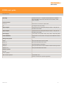
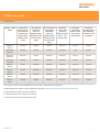
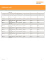
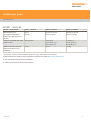
Mounting Multiwired autojoint - compatible with PH10M PLUS / PH10MQ
PLUS and PH6M probe heads, extension bars and ACR1 / ACR3
sensor changers
Crash protection
±X, ±Y, ‐Z Via break out of module or stylus holder
+Z Via integral bump-stop design
Signal outputs Non-linear and non-orthogonal analogue outputs - rate gain and
resolution are not fixed
Signal outputs Non-linear and non-orthogonal analogue outputs - rate gain and
resolution are not fixed
Power supply +12 V ﴾±5%﴿, ‐12 V ﴾+10% / +8%﴿, +5% ﴾+10% / ‐13%﴿ dc at probe
Probe calibration Requires that non-linear, third order polynomial calibration method
is used
Change rack options
FCR25 Three port unit which mounts on MRS
FCR25-L3 Three port standalone rack version
FCR25-L6 Six port standalone rack version
FCR25 TC Three port unit which mounts on MRS and warms scanning module
FCR25 TC-L3 Three port standalone rack version
Interface options
UCC S3
UCC2-2 systems
OEM controller systems AC3 interface card
Interface for TP20 also required if applicable
SP25M user's guide
www.renishaw.com
Issued 10 2019
19

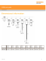
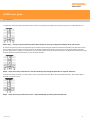
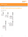
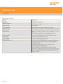
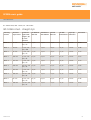
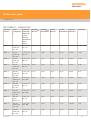
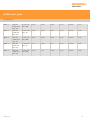
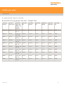
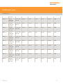
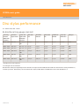
Dimensional information
SM25-1
SH25-1
SM25-2
SH25-2
SM25-2
SH25-2A
SM25-3
SH25-3
SM25-3
SH25-3A
SM25-4
SH25-4
SM25-4
SH25-4A
SM25-5
SH25-5
Range (mm) 20 - 50 20 - 75 20 - 75 20 - 100 20 - 100 20 - 200 20 - 200 20 - 100
EWL (mm) 20 - 50 50 - 105 50 - 105 120 - 200 120 - 200 220 - 400 220 - 400 20 - 100
SP25M user's guide
www.renishaw.com
Issued 10 2019
20
Pagina se încarcă...
Pagina se încarcă...
Pagina se încarcă...
Pagina se încarcă...
Pagina se încarcă...
Pagina se încarcă...
Pagina se încarcă...
Pagina se încarcă...
Pagina se încarcă...
Pagina se încarcă...
Pagina se încarcă...
Pagina se încarcă...
Pagina se încarcă...
Pagina se încarcă...
Pagina se încarcă...
Pagina se încarcă...
Pagina se încarcă...
Pagina se încarcă...
Pagina se încarcă...
Pagina se încarcă...
Pagina se încarcă...
Pagina se încarcă...
Pagina se încarcă...
Pagina se încarcă...
Pagina se încarcă...
Pagina se încarcă...
Pagina se încarcă...
Pagina se încarcă...
Pagina se încarcă...
Pagina se încarcă...
Pagina se încarcă...
Pagina se încarcă...
Pagina se încarcă...
Pagina se încarcă...
Pagina se încarcă...
Pagina se încarcă...
Pagina se încarcă...
Pagina se încarcă...
Pagina se încarcă...
Pagina se încarcă...
Pagina se încarcă...
Pagina se încarcă...
Pagina se încarcă...
Pagina se încarcă...
Pagina se încarcă...
Pagina se încarcă...
Pagina se încarcă...
Pagina se încarcă...
Pagina se încarcă...
Pagina se încarcă...
Pagina se încarcă...
Pagina se încarcă...
Pagina se încarcă...
Pagina se încarcă...
Pagina se încarcă...
Pagina se încarcă...
Pagina se încarcă...
Pagina se încarcă...
Pagina se încarcă...
Pagina se încarcă...
Pagina se încarcă...
Pagina se încarcă...
Pagina se încarcă...
Pagina se încarcă...
Pagina se încarcă...
Pagina se încarcă...
Pagina se încarcă...
Pagina se încarcă...
Pagina se încarcă...
Pagina se încarcă...
Pagina se încarcă...
Pagina se încarcă...
Pagina se încarcă...
Pagina se încarcă...
Pagina se încarcă...
Pagina se încarcă...
Pagina se încarcă...
Pagina se încarcă...
Pagina se încarcă...
Pagina se încarcă...
Pagina se încarcă...
Pagina se încarcă...
Pagina se încarcă...
Pagina se încarcă...
Pagina se încarcă...
Pagina se încarcă...
Pagina se încarcă...
Pagina se încarcă...
Pagina se încarcă...
Pagina se încarcă...
Pagina se încarcă...
Pagina se încarcă...
Pagina se încarcă...
Pagina se încarcă...
Pagina se încarcă...
Pagina se încarcă...
Pagina se încarcă...
Pagina se încarcă...
Pagina se încarcă...
Pagina se încarcă...
Pagina se încarcă...
Pagina se încarcă...
Pagina se încarcă...
Pagina se încarcă...
Pagina se încarcă...
Pagina se încarcă...
Pagina se încarcă...
Pagina se încarcă...
Pagina se încarcă...
Pagina se încarcă...
Pagina se încarcă...
Pagina se încarcă...
Pagina se încarcă...
-
 1
1
-
 2
2
-
 3
3
-
 4
4
-
 5
5
-
 6
6
-
 7
7
-
 8
8
-
 9
9
-
 10
10
-
 11
11
-
 12
12
-
 13
13
-
 14
14
-
 15
15
-
 16
16
-
 17
17
-
 18
18
-
 19
19
-
 20
20
-
 21
21
-
 22
22
-
 23
23
-
 24
24
-
 25
25
-
 26
26
-
 27
27
-
 28
28
-
 29
29
-
 30
30
-
 31
31
-
 32
32
-
 33
33
-
 34
34
-
 35
35
-
 36
36
-
 37
37
-
 38
38
-
 39
39
-
 40
40
-
 41
41
-
 42
42
-
 43
43
-
 44
44
-
 45
45
-
 46
46
-
 47
47
-
 48
48
-
 49
49
-
 50
50
-
 51
51
-
 52
52
-
 53
53
-
 54
54
-
 55
55
-
 56
56
-
 57
57
-
 58
58
-
 59
59
-
 60
60
-
 61
61
-
 62
62
-
 63
63
-
 64
64
-
 65
65
-
 66
66
-
 67
67
-
 68
68
-
 69
69
-
 70
70
-
 71
71
-
 72
72
-
 73
73
-
 74
74
-
 75
75
-
 76
76
-
 77
77
-
 78
78
-
 79
79
-
 80
80
-
 81
81
-
 82
82
-
 83
83
-
 84
84
-
 85
85
-
 86
86
-
 87
87
-
 88
88
-
 89
89
-
 90
90
-
 91
91
-
 92
92
-
 93
93
-
 94
94
-
 95
95
-
 96
96
-
 97
97
-
 98
98
-
 99
99
-
 100
100
-
 101
101
-
 102
102
-
 103
103
-
 104
104
-
 105
105
-
 106
106
-
 107
107
-
 108
108
-
 109
109
-
 110
110
-
 111
111
-
 112
112
-
 113
113
-
 114
114
-
 115
115
-
 116
116
-
 117
117
-
 118
118
-
 119
119
-
 120
120
-
 121
121
-
 122
122
-
 123
123
-
 124
124
-
 125
125
-
 126
126
-
 127
127
-
 128
128
-
 129
129
-
 130
130
-
 131
131
-
 132
132
-
 133
133


Renishaw SP25M Manualul utilizatorului
- Tip
- Manualul utilizatorului
în alte limbi
- English: Renishaw SP25M User guide
Lucrări înrudite
-
Renishaw SP25M Ghid de instalare
-
-
-
-
-
-
-
-
-