

General information
© 2013 ‐ 2020 Renishaw plc. All rights reserved.
This document may not be copied or reproduced in whole or in part, or transferred to any other media or language by any means, without the
prior written permission of Renishaw.
Disclaimer
WHILE CONSIDERABLE EFFORT WAS MADE TO VERIFY THE ACCURACY OF THIS DOCUMENT AT PUBLICATION, ALL WARRANTIES,
CONDITIONS, REPRESENTATIONS AND LIABILITY, HOWSOEVER ARISING, ARE EXCLUDED TO THE EXTENT PERMITTED BY LAW.
RENISHAW RESERVES THE RIGHT TO MAKE CHANGES TO THIS DOCUMENT AND TO THE EQUIPMENT, AND/OR SOFTWARE AND THE
SPECIFICATION DESCRIBED HEREIN WITHOUT OBLIGATION TO PROVIDE NOTICE OF SUCH CHANGES.
Trade marks
RENISHAW
®
, the probe symbol and REVO
®
are registered trade marks of Renishaw plc.
Renishaw product names, designations and the mark ‘apply innovation' are trade marks of Renishaw plc or its subsidiaries.
Other brand, product or company names are trade marks of their respective owners.
WEEE
The use of this symbol on Renishaw products and / or accompanying documentation indicates that the product should not be mixed with
general household waste upon disposal. It is the responsibility of the end user to dispose of this product at a designated collection point for
waste electrical and electronic equipment (WEEE) to enable reuse or recycling. Correct disposal of this product will help to save valuable
resources and prevent potential negative effects on the environment. For more information, please contact your local waste disposal service
or Renishaw distributor.
Warranty
Unless you and Renishaw have agreed and signed a separate written agreement, the equipment and/or software are sold subject to the
Renishaw Standard Terms and Conditions supplied with such equipment and/or software, or available on request from your local Renishaw
office.
Renishaw warrants its equipment and software for a limited period (as set out in the Standard Terms and Conditions), provided that they are
installed and used exactly as defined in associated Renishaw documentation. You should consult these Standard Terms and Conditions to find
out the full details of your warranty.
Equipment and/or software purchased by you from a third-party supplier is subject to separate terms and conditions supplied with such
equipment and/or software. You should contact your third-party supplier for details.
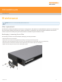
SPA3 installation guide
www.renishaw.com
Issued 08 2020
2

Care of equipment
Renishaw probes and associated systems are precision tools used for obtaining precise measurements and must therefore be treated with
care.
Changes to Renishaw products
Renishaw reserves the right to improve, change or modify its hardware or software without incurring any obligations to make changes to
Renishaw equipment previously sold.
Company registration details
Renishaw plc. Registered in England and Wales. Company no: 1106260. Registered office: New Mills, Wotton-under-Edge, Gloucestershire,
GL12 8JR, UK.
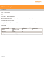
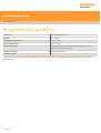
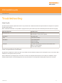
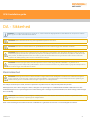
Packaging
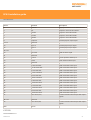
To aid end user recycling and disposal the materials used in the different components of the packaging are stated here:
Packaging component Material 94/62/EC code 94/62/EC number
Outer box Cardboard - 70% recycled
content
PAP 20
Packing foam Polyurethane PU 7
Packing foam Cross-linked polyethylene LDPE 4
Plastic bags Low density polyethylene bag LDPE 4
SPA3 installation guide
www.renishaw.com
Issued 08 2020
3

Product compliance
EU declaration of conformity
Contact Renishaw plc or visit www.renishaw.com/EUCMM for the full EU declaration.
EMC conformity
This equipment must be installed and used in accordance with this installation guide. This product is intended for industrial use only and
should not be used in a residential area or connected to a low voltage power supply network which supplies buildings used for residential
purposes.
FCC (USA only)
Information to user (47 CFR 15.105)
This equipment has been tested and found to comply with the limits for a Class A digital device, pursuant to Part 15 of the FCC rules. These
limits are designed to provide reasonable protection against harmful interference when the equipment is operated in a commercial
environment. This equipment generates, uses, and can radiate radio frequency energy and, if not installed and used in accordance with the
instruction manual, may cause harmful interference to radio communications. Operation of this equipment in a residential area is likely to
cause harmful interference, in which case you will be required to correct the interference at your own expense.
Information to user (47 CFR 15.21)
The user is cautioned that any changes or modifications not expressly approved by Renishaw plc or authorised representative could void the
user's authority to operate the equipment.
Equipment label (47 CFR 15.19)
This device complies with part 15 of the FCC Rules. Operation is subject to the following two conditions:
1. This device may not cause harmful interference.
2. This device must accept any interference received, including interference that may cause undesired operation.
SPA3 installation guide
www.renishaw.com
Issued 08 2020
4

REACH regulation
Information required by Article 33﴾1﴿ of Regulation ﴾EC﴿ No. 1907/2006 ﴾“REACH”﴿ relating to products containing substances of very high
concern (SVHCs) is available at:
www.renishaw.com/REACH
China RoHS
Contact Renishaw plc or visit www.renishaw.com/ChinaRoHSCMM for the full China RoHS tabulation.
SPA3 installation guide
www.renishaw.com
Issued 08 2020
5

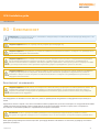
Safety
NOTE: For ambient temperatures under 40 °C the maximum output power for the SPA3 is 800 W. For temperatures between 40 °C
and 50 °C the maximum power is 400 W.
WARNING: SPA3 is not recommended for use in ambient temperatures above 50 °C.
WARNING: Earthing provisions for the complete machine is the responsibility of the OEM or installer.
WARNING: SPA3 is isolated from the power supply by disconnection of the ac power connector from the external PSU. If any
additional means of isolation is required, it must be specified and fitted by the machine manufacturer or the installer of the product.
The isolator must be sited within easy reach of the CMM operator and comply with IEC61010 and any applicable national wiring
regulations for the country of installation.
WARNING: The PSU must be single fault tolerant, approved to EN60950-1 and must be connected to a supply incorporating a
protective earth conductor. Earthing provisions and residual fault protection for the complete machine is the responsibility of the
OEM or installer.
Machine safety
WARNING: Switching off or isolating the SPA3 may NOT prevent unexpected machine movement. The user is advised to isolate
the machine from the electricity supply, compressed air or other energy sources in accordance with the machine manufacturer's
instructions before entering the danger zone or performing any maintenance operations.
If the equipment is used in a manner not specified by the manufacturer, the protection provided by the equipment may be impaired.
The emergency stop safety system that has been integrated into the SPA3 is designed to achieve category 2 to standard BS EN ISO13849-
1:2008. This can be hardware configured to obtain category B. The risk assessment made by the system installer on the installation should
therefore have determined which category is required.
CAUTION: It is strongly recommended that the CMM manufacturer or retrofitter includes a periodic test of the emergency stop
and if fitted, the associated reset switch in their maintenance instructions.
The SPA3 must only be commissioned through Renishaw software. Failure to do so may result in unexpected machine movement.
SPA3 installation guide
www.renishaw.com
Issued 08 2020
6

Environmental conditions
Indoor use IP30* (BS EN60529:1992)
Altitude Up to 2000 m
Operating temperature +5 °C to +50 °C
Storage temperature ‐25 °C to +70 °C
Relative humidity 80% maximum ﴾non‐condensing﴿ for temperatures up to +31 °C
Linear decrease to 50% at +40 °C
Transient voltages Overvoltage category I
Pollution degree 2
* It may be necessary to house SPA3 in a suitable electrical enclosure according to the installation's environmental conditions to obtain a
higher IP rating.
SPA3 installation guide
www.renishaw.com
Issued 08 2020
7

SPA3 system overview
SPA3 is a servo power amplifier with enhancements for higher power and category 2 E-STOP.
SPA3 can be used with UCC2, UCC2-2, UCC T3-2, UCC T3 PLUS, UCC S3, UCC T5 and UCC S5 and have different connection requirements.
The high power capability combined with a compact form enables use of the SPA3 across a wide range of machines.
The SPA3 CMM amplifier has the capability of:
Powering three axes of a CMM
Accepting input signals from air pressure, crash detection and all axis inner and outer travel limit switches (not connected when used with
UCC2 / UCC2-2)
Accepting two uncommitted general purpose input signals and generating one uncommitted general purpose output signal (not connected
when used with UCC2 / UCC2-2)
Directly supporting the TP1, TP2, TP6 and TP20 touch-trigger probes (not connected when used with UCC2 / UCC2-2)
Providing a +24 V supply for use by the CMM switches (not connected when used with UCC2 / UCC2-2)
The SPA3 supports the MCUlite-2 joystick, it can also support the MCU5, MCU5-2, MCU W and MCU W-2 (not connected when used with
UCC2 / UCC2-2)
Providing power output of up to 800 W continuous and 960 W for up to 1 second
Setting the voltage of each axis is independent allowing differing motor voltages to be used without damage
Supporting dc motors in the range 12 V to 80 V and currents up to 10 A
Supporting encoder / tacho or linear encoders (torque mode) for velocity feedback
Simulating linear power amplifier - drive outputs are free from switching edges eliminating noise from drive PWM, improving repeatability
and reducing emissions
Providing category 2 E-STOP
SPA3 installation guide
www.renishaw.com
Issued 08 2020
8

SPA3 installation software
The SPA3 is supported in UCCsuite version 4.4.6 software or later. The software can be obtained online at www.renishaw.com/cmmsupport or
from your local Renishaw supplier. Follow the prompts to install the UCCserver software.
CAUTION: Do not power down the SPA3 when the parameters or firmware is being updated. This can cause an error that requires
the unit to be returned to Renishaw.
UCCassist-2
The Renishaw UCCassist-2 program is a utility to assist the engineer to install, commission and maintain a UCC controlled CMM.
Capabilities of the software include:
Basic machine system diagnostics
Operation with Renishaw's machine checking gauge, enabling the user to complete frequent volumetric accuracy tests to ensure the CMM
is running within the specified operational tolerances
Automated CMM error mapping routines, when used in conjunction with the Renishaw ML10 or XL80 laser systems
SPA3 installation guide
www.renishaw.com
Issued 08 2020
9

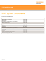
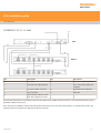
SPA3 system components
The part numbers of the SPA3 kits are:
Kit Part number
SPA3 amplifier kit 1 comprising of:
SPA3 amplifier
PSU 600 W 48 V to 58 V (medium / large machines)
A-5518-2550
A-5518-2500
A-5518-0025
SPA3 for use with UCC2-2 A-5629-0100
SPA3 A-5629-0200
SPA3 5-axis A-5629-0300
Accessories Part number
PSU 600 W 48 V to 58 V (medium / large machines) A-5518-0025
Connector kit A-5518-0010
Bracket kit A-5518-0005
E-STOP cable required for UCC2 or UCC2-2 A-5629-0090
SPA3 6-axis emergency stop cable A-5623-0095
SPA3 installation guide
www.renishaw.com
Issued 08 2020
10

General wiring standards for the installation of
the SPA3
To achieve reliable operation of the SPA3 plus UCC, the following should be observed:
The PSU must be single fault tolerant, approved to EN60950-1 and must be connected to a supply incorporating a protective earth
conductor (earthing provisions and residual fault protection for the complete machine are the responsibility of the OEM or installer)
The system must be PAT tested before the equipment is powered
All signal cables MUST be screened and all cable screens should be connected electrically to the cable connector's metal shells
It is recommended that screens for motor cables should be connected to the shell on the SPA3 end and connected to the motor housing at
the CMM end
Signal cables such as tacho and scale cables should be connected to the SPA3 and have a cable shield that runs to the machine but is left
unconnected at the machine end
Please refer to appropriate product installation guides when installing other Renishaw components
Supply and motor cables that are used to connect the SPA3 to the CMM (that are not data cables) must have a minimum cross section of
0.3 mm
2
(as specified in EN 60204-1 para.12.6.)
SPA3 has a maximum voltage of 80 Vdc and peak current is 10 A (the actual peak current will be dependent on the size of the motor fitted
and how hard it needs to be driven, so cable sizes need to be calculated by the system installer)
All cable connectors should be secured to the SPA3 by the connector jack screws.
The power input to the SPA3 is via a 3W3 connector; refer to the Connector and signals section for more information.
SPA3 power requirements
The SPA3 amplifier requires 30 W of power to operate. This must be factored into the power supply used.
SPA3 installation guide
www.renishaw.com
Issued 08 2020
11

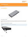
Installation
Mounting the SPA3
The SPA3 unit draws air from the right hand side when viewed from the front and expels air out of the left hand side. A minimum clearance
gap of 10 mm is necessary between the sides of the unit and any potential obstruction. The dimensions shown on the above drawing are in
mm (in).
Fitting mounting brackets (optional)
NOTE: The screws supplied with this kit are M5 × 6 mm countersink type.
SPA3 installation guide
www.renishaw.com
Issued 08 2020
12


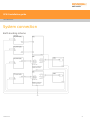
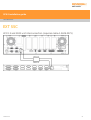
Installation for 4 - 6 axes
Key Description Key Description
1 Head cable 6 24 V power supply (supplied)
2 CAT 5 300 mm cable (supplied) 7 25 V - 80 V power supply (not
supplied)
3 16 / 0.2 mm earth connection 8 E-STOP link cable (supplied)
4 MCU connection 9 TEC input
5 CAT 5 ethernet cable (5 m cross-
over cable supplied) to host PC
The head and CMM system are operated through UCCserver which uses I++DME command protocol to communicate between the system
application software and the UCC.
Full 5-axis scanning capability is achieved through interaction between the UCC, the head and the SPA3, to co-ordinate all the motion and
metrology aspects across the three CMM axes and the two head axes.
SPA3 installation guide
www.renishaw.com
Issued 08 2020
14

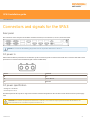
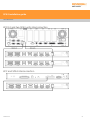
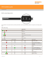
Connectors and signals for the SPA3
Rear panel
The connectors on the rear panel of the SPA3 controller enclosure (for use with UCC2 / UCC2-2) are shown below:
NOTE: Do not remove the blanking plugs when used in conjunction with UCC2 or UCC2-2.
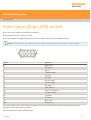
DC power in
3W3 socket. The SPA3 is powered from an external dc power source through this connector. This and all other connectors and shells can be
purchased in a connector kit from Renishaw (part number A-5518-0010).
Pin no. Function
A1 0 V
A2 24 V to 80 Vdc
A3 Reserved
DC power specification
• Voltage 24 V to 80 Vdc
• Current input to 10 A
The SPA3 requires 30 W of power to support the controller functions integrated into the unit. This must be factored into the power supply
used.
CAUTION: For ambient temperatures between 40 °C and 50 °C, the maximum output power should be 400 W. SPA3 is not
recommended for use in ambient temperatures above 50 °C.
SPA3 installation guide
www.renishaw.com
Issued 08 2020
15

Axis0, Axis1 and Axis2 motor drive connectors
(7w2 D socket)
Each motor connection is a 7W2 connector for connection of a CMM motor to the SPA3, as shown below:
Pin no. Function
A1 Positive motor connection (default)
A2 Negative motor connection (default)
1 Positive tacho input (default)
2 * Negative tacho input
3 (tacho) screen
4 * Negative tacho input
5 (tacho) screen
Shell Screen (motor)
The table shows the default polarity configurations for all pins.
* NOTE: The motor and tacho polarities on the SPA3 are software configured during the installation process. The maximum tacho
voltage is 100 V. If one terminal of the tacho is grounded the maximum voltage is reduced to 18 V. It is recommended that a
differential tacho is used.
CAUTION: The SPA3 motor connections must be blanked off if not being used to prevent accidental contact which could result in
an electric shock.
SPA3 installation guide
www.renishaw.com
Issued 08 2020
16

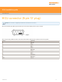
MCU connector (9-pin 'D' plug)
NOTE: This connector is supplied pre-blanked for use with UCC2 or UCC2-2.
Remove the blanking plug AND jumper between pin 8 and 9 when installing with any other controller.
This is a 9-pin D-plug suitable for direct connection to the MCUlite-2, MCU5, MCU5-2, MCU W or MCU W-2 joystick.
Pin no. Function
1 Ground
2 RX_B
3 RX_A
4 TX_A
5 Reserved
6 +12 V
7 TX_B
8 E-STOP_B
9 E-STOP_A
Shell Screen
SPA3 installation guide
www.renishaw.com
Issued 08 2020
17

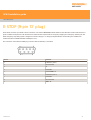
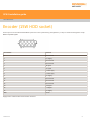
E-STOP (9-pin 'D' plug)
The E-STOP connector is provided to allow connection of an external EMERGENCY STOP switch into the SPA3. The machine manufacturer or
product installer must perform a risk assessment to determine the requirements for emergency stopping and emergency switching off. The
SPA3 emergency stop safety system is designed to achieve category 2 or category B implementation as selected by the installer's risk
assessment (refer to BS EN ISO13849-1:2008 para. 5.2.2.).
The connection on the SPA3 is a 9WD plug connector with the following connections:
Pin no. Function
1 E-STOP A1 (+24V)
2 Not connected
3 0V
4 E-STOP B1
5 E-STOP RESET "A"
6 E-STOP A2 (+24 V)
7 E-STOP B2
8 Not connected
9 RESET "B"
SPA3 installation guide
www.renishaw.com
Issued 08 2020
18

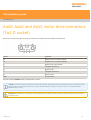
E-STOP electrical characteristics
Any emergency stop components fitted to this connector must have the following electrical characteristics:
Emergency stop system voltage : 24 V
Emergency stop system current : 300 mA max
All connections to this connector should be fitted by a competent technician or engineer and all wires should be sleeved. Any emergency stop
devices added to the E‐STOP chain should meet the requirements of IEC 60947‐5‐1 ﴾Low‐voltage switchgear and control gear – Part 5‐1:
Control circuit devices and switching elements – Electromechanical control circuit devices﴿ or UL1054 ﴾Standard for special‐use switches﴿.
NOTE: If there are no additional emergency stop devices to be added to the system, connect pin 1 to pin 4, and pin 6 to pin 7 to
permit the SPA3 emergency stop switch to function.
NOTE: If the RESET signal is not used connect pin 5 (RESET "A") to pin 9 (RESET "B").
If indicated by the user's risk assessment, a ‘manual reset' button ﴾refer to BS EN ISO13849‐1:2008 para. 5.2.2.﴿ should be included in the
emergency stop system. A reset switch is required when there is limited visibility of the danger zone from the control position. The reset
switch must be positioned outside the danger zone and in a safe position from which it may be determined that no person is within the
danger zone before resetting the safety system.
CAUTION: It is strongly recommended that the CMM manufacturer or retrofitter includes a periodic test of the emergency stop
and, if fitted, the associated reset switch in their maintenance instructions.
SPA3 installation guide
www.renishaw.com
Issued 08 2020
19

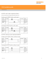
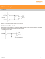
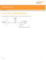
E-STOP with reset implementation
There are five methods of implementing the E-STOP circuit;
Single pole E-STOP button with reset
Dual pole E-STOP button with reset
E-STOP without reset implementation
Single pole E-STOP button without reset
Dual pole E-STOP button without reset
SPA3 installation guide
www.renishaw.com
Issued 08 2020
20
Pagina se încarcă...
Pagina se încarcă...
Pagina se încarcă...
Pagina se încarcă...
Pagina se încarcă...
Pagina se încarcă...
Pagina se încarcă...
Pagina se încarcă...
Pagina se încarcă...
Pagina se încarcă...
Pagina se încarcă...
Pagina se încarcă...
Pagina se încarcă...
Pagina se încarcă...
Pagina se încarcă...
Pagina se încarcă...
Pagina se încarcă...
Pagina se încarcă...
Pagina se încarcă...
Pagina se încarcă...
Pagina se încarcă...
Pagina se încarcă...
Pagina se încarcă...
Pagina se încarcă...
Pagina se încarcă...
Pagina se încarcă...
Pagina se încarcă...
Pagina se încarcă...
Pagina se încarcă...
Pagina se încarcă...
Pagina se încarcă...
Pagina se încarcă...
Pagina se încarcă...
Pagina se încarcă...
Pagina se încarcă...
Pagina se încarcă...
Pagina se încarcă...
Pagina se încarcă...
Pagina se încarcă...
Pagina se încarcă...
Pagina se încarcă...
Pagina se încarcă...
Pagina se încarcă...
Pagina se încarcă...
Pagina se încarcă...
-
 1
1
-
 2
2
-
 3
3
-
 4
4
-
 5
5
-
 6
6
-
 7
7
-
 8
8
-
 9
9
-
 10
10
-
 11
11
-
 12
12
-
 13
13
-
 14
14
-
 15
15
-
 16
16
-
 17
17
-
 18
18
-
 19
19
-
 20
20
-
 21
21
-
 22
22
-
 23
23
-
 24
24
-
 25
25
-
 26
26
-
 27
27
-
 28
28
-
 29
29
-
 30
30
-
 31
31
-
 32
32
-
 33
33
-
 34
34
-
 35
35
-
 36
36
-
 37
37
-
 38
38
-
 39
39
-
 40
40
-
 41
41
-
 42
42
-
 43
43
-
 44
44
-
 45
45
-
 46
46
-
 47
47
-
 48
48
-
 49
49
-
 50
50
-
 51
51
-
 52
52
-
 53
53
-
 54
54
-
 55
55
-
 56
56
-
 57
57
-
 58
58
-
 59
59
-
 60
60
-
 61
61
-
 62
62
-
 63
63
-
 64
64
-
 65
65


în alte limbi
- English: Renishaw SPA3 Installation guide
- slovenčina: Renishaw SPA3 Návod na inštaláciu
- polski: Renishaw SPA3 Instrukcja instalacji
- eesti: Renishaw SPA3 paigaldusjuhend
- italiano: Renishaw SPA3 Guida d'installazione
Lucrări înrudite
-
Renishaw Retrofit cabinet Installation & User's Guide
-
-
-
-
Renishaw REVO-2 Manualul utilizatorului
-
-
-
-
-