
Via Marconi, 3/A - Loc. Vermezzo
20071 Vermezzo con Zelo (MI) - ITALY
Tel +39 02 946941 - Fax +39 02 94941040
e-mail: [email protected] - www.rupes.com
IT Levigatrici rotorbitali pneumatiche ....................................................................................................... 2
EN Random-orbital pneumtic sanders........................................................................................................ 6
FR Ponceuses rotorbitales pneumatiques ............................................................................................... 10
DE Pneumatische Exzenterschleifer ......................................................................................................... 14
ES Lijadoras rotórbitales neumáticas ...................................................................................................... 18
NL Pneumatisch roterend excentrische schuurmachine ....................................................................... 22
RU Пневматическиевращательно-орбитальныешлифовальныемашины ................................. 26
AR ................................................................................................................................................................ 30
BG Пневматичниорбиталнишлайфмашини ........................................................................................ 34
ZH 气动式转子砂光机气动式转子砂光机 ............................................................................................................................. 38
CS Pneumatické excentrické brusky ........................................................................................................ 42
DA Pneumatiske roterende slibemaskiner ............................................................................................... 46
ET Pneumaatilised ekstsentriklihvmasinad ............................................................................................. 50
FI Paineilmakäyttöiset kehähiomakoneet ............................................................................................... 54
EL Λειαντικάμηχανήματαπεριστροφικήςκίνησηςπεπιεσμένουαέρα[τριβεία] ................................ 58
HU Levegősrotációscsiszoló ................................................................................................................... 62
HI रैंडम-ऑर्बिटल न्यूमेटिक सैंडर्स ........................................................................................................................ 66
LT Pneimatiskāsorbitālāsslīpmašīnas ................................................................................................... 70
LV Pneumatinėsžiedinėsšlifavimostaklės............................................................................................. 74
PL Szlifierkioscylacyjnepneumatyczne .................................................................................................. 78
PT Lixadoras orbitais especiais pneumáticas ......................................................................................... 82
RO Mașinideșlefuitpneumaticeroto-orbitale ......................................................................................... 86
SK Pneumatickérotačnéorbitálnebrúsky ............................................................................................... 90
SL Ekscentričnipnevmatskibrusilniki ..................................................................................................... 94
SV Pneumatiska excenterslipmaskiner .................................................................................................... 98
RH323
RH323A
RH323T
RH326
RH326A
RH326T
RH329
RH329A
RH329T
RH353
RH353A
RH353T
RH356
RH356A
RH356T
RH359
RH359A
RH359T

2
Attenzione pericolo
ATTENZIONE: E’ importante che l’utente legga il manuale di istruzione per ridurre il rischio di lesioni
Indossare gli occhiali protettivi
Indossare le protezioni acustiche
Indossare una maschera
Marcatura CE per il mercato EU
L’utensile è inserito nella lista CU TR
Ø Diametro Diametro del disco, platorello, orbita...
n0 Velocità a vuoto Velocità del rotante
.../min. Giri al minuto Velocità
Freccia Agire in direzione indicata dal senso della freccia
2
ITALIANO
SIMBOLI GRAFICI
ISTRUZIONI ORIGINALI PER L’USO
Attenzione pericolo
Leggere le istruzioni/avvertenze
Indossare gli occhiali protettivi
Indossare le protezioni acustiche
Indossare una maschera
Marcatura di conformità
L’utensile è inserito nella lista CU TR
Ø
Diametro Diametro del disco, platorello, orbita...
n
0
Velocità a vuoto Velocità del rotante
.../min.
Giri al minuto Velocità
Freccia Agire in direzione indicata dal senso della freccia
2
DATI TECNICI
Levigatrici rotorbitali pneumatiche RH223 RH253 RH226 RH256 RH229 RH259
Pressione max.di entrata [bar/PSI] 6.2 / 90 6.2 / 90 6.2 / 90
Consumo aria [l/min] 340 340 340
Giri a vuoto n0 [/min] 0 - 11.000 0 - 11.000 0 - 11.000
Ø orbita [mm] 3 6 9
Ø platorello [mm] 125 150 125 150 125 150
Sistema di aspirazione NO NO NO
Massa [Kg] 0.800 0.800 0.800
RH223 - RH226 - RH229 RH253 - RH256 - RH259
Alcuni dei seguenti simboli possono essere presenti sul vostro utensile. Si prega di studiarli e imparare loro il significato.
Una corretta interpretazione permetterà un utilizzo migliore e sicuro dell’utensile.
2
RH323 - RH326 - RH329 RH353 - RH356 - RH359
RH323 RH353 RH326 RH356 RH329 RH359
ITALIANO
SIMBOLI GRAFICI ISTRUZIONI ORIGINALI PER L’USO
WARNING
2
Alcuni dei seguenti simboli possono essere presenti sul vostro utensile. Si prega di studiarli e imparare loro il signicato.
Una corretta interpretazione permetterà un utilizzo migliore e sicuro dell’utensile.
DATI TECNICI
Levigatrici rotorbitali pneumatiche RH323 RH353 RH326 RH356 RH329 RH359
Pressione max.di entrata [bar/PSI] 6.2 / 90 6.2 / 90 6.2 / 90
Consumo aria [l/min] 340 340 340
Giri a vuoto n0 [/min] 0 - 11.000 0 - 11.000 0 - 11.000
Ø orbita [mm] 3 6 9
Ø platorello [mm] 125 150 125 150 125 150
Sistema di aspirazione NO NO NO
Massa [Kg] 0.833 0.847 0.858
Ingresso aria 1/4” 1/4” 1/4”

3
3
DATI TECNICI
L’utensile deve funzionare collegato ad uno opportuno sistema di aspirazione (non fornito)
Levigatrici rotorbitali pneumatiche RH223A RH253A RH226A RH256A RH229A RH259A
Pressione max.di entrata [bar/PSI] 6.2 / 90 6.2 / 90 6.2 / 90
Consumo aria [l/min] 340 340 340
Giri a vuoto n0 [/min] 0 - 11.000 0 - 11.000 0 - 11.000
Ø orbita [mm] 3 6 9
Ø platorello [mm] 125 150 125 150 125 150
Sistema di aspirazione CENTRALIZZATO CENTRALIZZATO CENTRALIZZATO
Massa [Kg] 0.800 0.800 0.800
DATI TECNICI
Levigatrici rotorbitali pneumatiche RH223T RH253T RH226T RH256T RH229T RH259T
Pressione max.di entrata [bar/PSI] 6.2 / 90 6.2 / 90 6.2 / 90
Consumo aria [l/min] 340 340 340
Giri a vuoto n0 [/min] 0 - 11.000 0 - 11.000 0 - 11.000
Ø orbita [mm] 3 6 9
Ø platorello [mm] 125 150 125 150 125 150
Sistema di aspirazione AUTOASPIRANTE AUTOASPIRANTE AUTOASPIRANTE
Massa [Kg] 0.800 0.800 0.800
L’utensile deve funzionare collegato al tubo di aspirazione polveri collegato all’unità filtro.
RH223A - RH226A - RH229A RH253A - RH256A - RH259A
RH223T - RH226T - RH229T RH253T - RH256T - RH259T
RH323A RH353A RH326A RH356A RH329A RH359A
RH323T RH353T RH326T RH356T RH329T RH359T
RH323A - RH326A - RH329A RH353A - RH356A - RH359A
RH323T - RH326T - RH329T RH353T - RH356T - RH359T
DATI TECNICI
Levigatrici rotorbitali pneumatiche RH323A RH353A RH326A RH356A RH329A RH359A
Pressione max.di entrata [bar/PSI] 6.2 / 90 6.2 / 90 6.2 / 90
Consumo aria [l/min] 340 340 340
Giri a vuoto n0 [/min] 0 - 11.000 0 - 11.000 0 - 11.000
Ø orbita [mm] 3 6 9
Ø platorello [mm] 125 150 125 150 125 150
Sistema di aspirazione CENTRALIZZATO CENTRALIZZATO CENTRALIZZATO
Massa [Kg] 0.866 0.886 0.892
Ingresso aria 1/4” 1/4” 1/4”
L’utensile deve funzionare collegato ad uno opportuno sistema di aspirazione (non fornito)
3
DATI TECNICI
L’utensile deve funzionare collegato ad uno opportuno sistema di aspirazione (non fornito)
Levigatrici rotorbitali pneumatiche RH223A RH253A RH226A RH256A RH229A RH259A
Pressione max.di entrata [bar/PSI] 6.2 / 90 6.2 / 90 6.2 / 90
Consumo aria [l/min] 340 340 340
Giri a vuoto n0 [/min] 0 - 11.000 0 - 11.000 0 - 11.000
Ø orbita [mm] 3 6 9
Ø platorello [mm] 125 150 125 150 125 150
Sistema di aspirazione CENTRALIZZATO CENTRALIZZATO CENTRALIZZATO
Massa [Kg] 0.800 0.800 0.800
DATI TECNICI
Levigatrici rotorbitali pneumatiche RH223T RH253T RH226T RH256T RH229T RH259T
Pressione max.di entrata [bar/PSI] 6.2 / 90 6.2 / 90 6.2 / 90
Consumo aria [l/min] 340 340 340
Giri a vuoto n0 [/min] 0 - 11.000 0 - 11.000 0 - 11.000
Ø orbita [mm] 3 6 9
Ø platorello [mm] 125 150 125 150 125 150
Sistema di aspirazione AUTOASPIRANTE AUTOASPIRANTE AUTOASPIRANTE
Massa [Kg] 0.800 0.800 0.800
L’utensile deve funzionare collegato al tubo di aspirazione polveri collegato all’unità filtro.
RH223A - RH226A - RH229A RH253A - RH256A - RH259A
RH223T - RH226T - RH229T RH253T - RH256T - RH259T
RH323A RH353A RH326A RH356A RH329A RH359A
RH323T RH353T RH326T RH356T RH329T RH359T
RH323A - RH326A - RH329A RH353A - RH356A - RH359A
RH323T - RH326T - RH329T RH353T - RH356T - RH359T
DATI TECNICI
Levigatrici rotorbitali pneumatiche RH323T RH353T RH326T RH356T RH329T RH359T
Pressione max.di entrata [bar/PSI] 6.2 / 90 6.2 / 90 6.2 / 90
Consumo aria [l/min] 340 340 340
Giri a vuoto n0 [/min] 0 - 11.000 0 - 11.000 0 - 11.000
Ø orbita [mm] 3 6 9
Ø platorello [mm] 125 150 125 150 125 150
Sistema di aspirazione AUTOASPIRANTE AUTOASPIRANTE AUTOASPIRANTE
Massa [Kg] 0.857 0.874 0.883
Ingresso aria 1/4” 1/4” 1/4”
L’utensile deve funzionare collegato al tubo di aspirazione polveri collegato all’unità ltro

4
AVVERTENZE GENERALI
Le istruzioni per la sicurezza e la prevenzione degli infortuni sono
riportate nel fascicolo “INDICAZIONI PER LA SICUREZZA” che
costituisce parte integrante della presente documentazione, il
presente MANUALE D’ISTRUZIONI per l’uso riporta solamente le
informazioniaggiuntivestrettamentecorrelateall’usospecifico
dell’utensile.
UTILIZZO CONFORME AGLI SCOPI PREVISTI
Questo utensile è destinato a funzionare come levigatrice.
Leggere tutti gli avvertimenti di sicurezza, le istruzioni, le
illustrazionielespecificheforniticonquestoutensile.
Il mancato rispetto di tutte le istruzioni sotto riportate può causare
una scossa elettrica, un incendio e/o un incidente grave.
Le operazioni di molatura, lucidatura, spazzolatura metallica o
di taglio non sono consigliate con questo utensile. Le operazioni
per le quali l’utensile non è previsto possono provocare un pericolo e
causare danni alle persone.
VALORI DI EMISSIONE ACUSTICA
Valori di emissione acustica rilevati conformemente a EN ISO 15744:
Livello di pressione Incertezza Livello di potenza
acustica [dB(A)] (dB) sonora [dB(A)]
LpA K LwA
RH323-RH353 72.7 3.0 83.7
RH326-RH356 72.7 3.0 83.7
RH329-RH359 72.7 3.0 83.7
RH323A-RH353A 75.0 3.0 86.0
RH326A-RH356A 75.0 3.0 86.0
RH329A-RH359A 75.0 3.0 86.0
RH323T-RH353T 83.6 3.0 94.6
RH326T-RH356T 83.6 3.0 94.6
RH329T-RH359T 83.6 3.0 94.6
Indossarelecuffieprotettive!
LIVELLO DI VIBRAZIONI
Valori di oscillazione totali ah (somma vettoriale delle tre direzioni) e
grado d’incertezza K, rilevati conformemente a EN ISO 28927-3:
Su 3 assi Incertezza
ah K
RH323-RH353 2.8 1.0
RH326-RH356 2.8 1.0
RH329-RH359 2.8 1.0
RH323A-RH353A 3.0 1.1
RH326A-RH356A 3.0 1.1
RH329A-RH359A 3.0 1.1
RH323T-RH353T 3.2 1.5
RH326T-RH356T 3.2 1.5
RH329T-RH359T 3.2 1.5
I valori di emissione indicati sono comparativi e utilizzabili per una
valutazione provvisoria dei rischi di esposizione dell’operatore
durante il periodo di lavoro. La corretta valutazione del periodo
di lavoro deve comprendere anche i tempi di funzionamento a
vuoto e di arresto dell’utensile. I valori di emissioni indicati sono
rappresentativi delle principali applicazioni dell’utensile. Se l’utensile
viene utilizzato per altre applicazioni, con altri accessori o se non
viene sottoposto a regolare manutenzione, i valori di emissione
possono aumentare sensibilmente durante il funzionamento.
PARTI DELLA MACCHINA
1. Etichetta di identicazione
2. Leva di comando immissione aria compressa
3. Comando regolatore di velocità
4. Corpo macchina
5. Attacco aria compressa
6. Attacco tubo di aspirazione Ø int. 29 /25 mm
(SERIE RH..A- RH..T)
7. Silenziatore
8. Cufa di aspirazione (SERIE RH..A- RH..T)
9. Platorello
10. Vite di ssaggio del platorello
11. Olio lubricante
12. Chiave a brugola
13. Unità ltro : cartuccia (a) e porta-ltro (b) (SERIE RH..T)
14. Tubo di aspirazione polveri (SERIE RH..T)
MESSA IN FUNZIONE
Prima di mettere in funzione la macchina accertarsi che:
- l’imballo sia integro e non mostri segni di danneggiamento
dovuti a trasporto e magazzinaggio;
- l’impianto di produzione e distribuzione di aria compressa
a disposizione sia in grado di soddisfare i requisiti indicati
in tabella e riportati sulla targhetta di identicazione della
macchina.
MONTAGGIO DELLA MACCHINA
Montare il raccordo di adduzione aria compressa (non fornito)
avvitandolo nella apposita sede (5).
Assicurarsi che, quando viene allacciata l'aria compressa,
la leva di azionamento (2) dell'utensile pneumatico sia
disinserita.
Per l'alimentazione dell'aria compressa deve essere impiegato
un compressore adeguato alle caratteristiche tecniche riportate
nell’etichetta dati dell’utensile.
Tutti gli strumenti, le tubazioni di collegamento ed i tubi devono
essere adatti alla rispettiva pressione ed alla quantità di aria
necessaria.
RACCORDO DI ADDUZIONE ARIA COMPRESSA
(NON FORNITO)
La macchina viene fornita sprovvista del raccordo di adduzione
aria compressa; a scelta dell’utilizzatore possono essere usati
sia raccordi ad innesto rapido sia portagomma adeguati purchè
entrambi abbiano un foro di passaggio aria da mm. 8.
Nel secondo caso occorre ssare stabilmente con una fascetta
stringitubo il tubo di alimentazione al portagomma.
AVVIAMENTO E FERMATA
- Avviamento: spingere la leva di comando (2) verso il corpo
macchina e mantenerla premuta;
- fermata: rilasciare la leva di comando.

5
IMPOSTAZIONI
Prima di eseguire qualsiasi intervento sull’utensile, scollegare
sempre l’utensile dall'alimentazione dell'aria compressa.
REGOLAZIONE DEL NUMERO DI GIRI
La regolazione del numero dei giri si ottiene manovrando
opportunamente il regolatore (3) da OFF a MAX.
La scelta della velocità va fatta in funzione delle caratteristiche
dei dischi di carta abrasiva e del materiale da lavorare.
SOSTITUZIONE DEL PLATORELLO
Sostituire immediatamente un platorello danneggiato.
Risultati ottimali si conseguono solo con accessori
originali.
Il montaggio di un platorello di dimensioni errate può causare
vibrazioni eccessive e non ammesse per la macchina.
- Svitare con la chiave (12) la vite di ssaggio del platorello
(10) nel senso indicato dalla freccia riportato sulla cufa di
protezione;
- per il montaggio operare in senso inverso.
MONTAGGIO/ SOSTITUZIONE DEI DISCHI DI CARTA
ABRASIVA
La supercie del platorello è realizzata in materiale adatto alla
ricezione dei dischi di carta abrasivi e permette una facile e
veloce aderenza dei dischi di carta abrasivi.
MONTAGGIO:
- Fare aderire mediante pressione il disco di carta abrasiva al
platorello avendo cura che i fori del disco di carta abrasiva
coincidano con i fori di aspirazione esistenti sul platorello.
SOSTITUZIONE:
- Asportare a strappo il disco di carta abrasiva usato;
- applicare il nuovo disco di carta abrasiva (vedi MONTAGGIO).
Nota: per una migliore aderenza è consigliato rimuovere polvere e
sporco dalla supercie del platorello.
UTENSILI DI LAVORO AMMESSI
Dischi di carta abrasiva Ø 125 mm - Ø 150 mm con fori per
l’aspirazione.
PRIMA DELLA MESSA IN SERVIZIO
Accertarsi che:
- il regolatore di velocità (3) sia nella posizione MAX;
- raccordo e tubo di adduzione aria compressa siano in perfetto
stato;
- il dispositivo di azionamento sia efciente operando però a
macchina non alimentata;
- tutti i componenti della macchina siano montati correttamente
e non presentino segni di danneggiamento;
- la macchina sia correttamente collegata ad un sistema
d’aspirazione idoneo ed efciente (serie RH..A ed RH..T).
INDICAZIONI OPERATIVE
- Avviare la macchina e controllare che non siano presenti
vibrazioni anomale, che i fogli di carta abrasivi siano applicati
in modo corretto (vedi MONTAGGIO/ SOSTITUZIONE DEI
DISCHI DI CARTA ABRASIVA ).
In caso contrario spegnere la macchina immediatamente e
provvedere ad eliminare le anomalie.
- Fissare il pezzo in lavorazione in modo da evitare possibili
movimenti durante la lavorazione.
Usare sempre una maschera in caso di lavori che producono
polvere.
MANUTENZIONE
Tutte le operazioni di manutenzione e pulizia vanno
eseguite a macchina scollegata dall’alimentazione
dell’aria compressa.
Le operazioni di manutenzione e riparazione devono essere
eseguite da personale qualicato.
A ne lavoro, od in caso di necessità, spolverare con getto di aria
compressa il corpo macchina.
MANUTENZIONE ORDINARIA:
Lubricare periodicamente (ogni 50 ore di lavoro) la macchina
inserendo 2/3 gocce d'olio per uso specico (11) nell'attacco aria
compressa dell'utensile tenendo lo stesso in posizione verticale con
l'attacco in alto. Dopo questa operazione collegare la macchina
all'alimentazione e azionarla per alcuni secondi.
Prima di riporre l'utensile per un lungo periodo di inattività procedere
all'operazione di lubricazione come sopra descritto.
Si escludono dalla garanzia tutti i danni derivanti da una scorretta o
inadeguata lubricazione.
Non sono ammessi altri interventi da parte dell'utente.
Per la manutenzione e la periodica pulizia delle parti interne, come
cuscinetti, ingranaggi, etc. o altre necessità rivolgersi ai Centri di
Assistenza autorizzati consultabili anche sul sito www.rupes.com
sezione Service.
Utilizzare solo ricambi originali RUPES.
SMALTIMENTO
Il prodotto, quando giunge a ne vita, non deve essere disperso
nell’ambiente o gettato tra i riuti domestici, ma deve essere
smaltito presso i centri di raccolta differenziata autorizzati
(contattare le autorità locali competenti per conoscere dove
smaltire il prodotto secondo le norme di legge). Il corretto
smaltimento del prodotto contribuisce alla tutela della salute
e alla salvaguardia dell’ambiente.Lo smaltimento abusivo del
prodotto comporta sanzioni a carico dei trasgressori.
DICHIARAZIONE DI CONFORMITÀ UE
Dichiariamo sotto la nostra responsabilità che l’utensile portatile,
al quale fa riferimento il presente manuale, è conforme ai
Requisiti Essenziali della Direttiva: 2006/42/CE Macchine.
Le prove/veriche sono eseguite in accordo alle seguenti
Normative: EN ISO 11148-8:2011, EN ISO 15744:2008,
EN ISO 28927-3:2009.
Vermezzo con Zelo (MI), 16/06/2022
Fascicolo tecnico presso:
RUPES S.p.A.
Via Marconi, 3/A - Loc. Vermezzo
20071 - Vermezzo con Zelo (MI) - Italia
Il presidente
G. Valentini

6
Warning symbol
WARNING: To reduce the risk of injury, user must read instruction manual
Wear eye protection
Wear ear protection
Wear a mask
CE marking for EU market
This symbol designates that this tool is listed by under CU TR compliant
Ø Diameter Size of drill bits, grindings wheels…
n0 No load speed Rotation speed at no load
.../min. Revolution or reciprocation per minute Revolutions, strokes, surface speed, orbits.. per minute
Arrow Action in the direction of arrow
2
ITALIANO
SIMBOLI GRAFICI
ISTRUZIONI ORIGINALI PER L’USO
Attenzione pericolo
Leggere le istruzioni/avvertenze
Indossare gli occhiali protettivi
Indossare le protezioni acustiche
Indossare una maschera
Marcatura di conformità
L’utensile è inserito nella lista CU TR
Ø
Diametro Diametro del disco, platorello, orbita...
n
0
Velocità a vuoto Velocità del rotante
.../min.
Giri al minuto Velocità
Freccia Agire in direzione indicata dal senso della freccia
2
DATI TECNICI
Levigatrici rotorbitali pneumatiche RH223 RH253 RH226 RH256 RH229 RH259
Pressione max.di entrata [bar/PSI] 6.2 / 90 6.2 / 90 6.2 / 90
Consumo aria [l/min] 340 340 340
Giri a vuoto n0 [/min] 0 - 11.000 0 - 11.000 0 - 11.000
Ø orbita [mm] 3 6 9
Ø platorello [mm] 125 150 125 150 125 150
Sistema di aspirazione NO NO NO
Massa [Kg] 0.800 0.800 0.800
RH223 - RH226 - RH229 RH253 - RH256 - RH259
Alcuni dei seguenti simboli possono essere presenti sul vostro utensile. Si prega di studiarli e imparare loro il significato.
Una corretta interpretazione permetterà un utilizzo migliore e sicuro dell’utensile.
2
RH323 - RH326 - RH329 RH353 - RH356 - RH359
RH323 RH353 RH326 RH356 RH329 RH359
ENGLISH
SYMBOLS TRANSLATION OF THE ORIGINAL INSTRUCTIONS
WARNING
6
Some of the following symbols may be used on your tool. Please study them and learn their meaning. Proper interpretation of these symbol
will allow you to operate the tool better and safer.
TECHNICAL DATA
Random-orbital pneumatic sanders RH323 RH353 RH326 RH356 RH329 RH359
Max. working pressure [bar/PSI] 6.2 / 90 6.2 / 90 6.2 / 90
Air consumption [l/min] 340 340 340
Rpm n0 [/min] 0 - 11.000 0 - 11.000 0 - 11.000
Ø orbit [mm] 3 6 9
Ø pad [mm] 125 150 125 150 125 150
Extraction system NO NO NO
Weight [Kg] 0.833 0.847 0.858
Air inlet 1/4” 1/4” 1/4”

7
3
DATI TECNICI
L’utensile deve funzionare collegato ad uno opportuno sistema di aspirazione (non fornito)
Levigatrici rotorbitali pneumatiche RH223A RH253A RH226A RH256A RH229A RH259A
Pressione max.di entrata [bar/PSI] 6.2 / 90 6.2 / 90 6.2 / 90
Consumo aria [l/min] 340 340 340
Giri a vuoto n0 [/min] 0 - 11.000 0 - 11.000 0 - 11.000
Ø orbita [mm] 3 6 9
Ø platorello [mm] 125 150 125 150 125 150
Sistema di aspirazione CENTRALIZZATO CENTRALIZZATO CENTRALIZZATO
Massa [Kg] 0.800 0.800 0.800
DATI TECNICI
Levigatrici rotorbitali pneumatiche RH223T RH253T RH226T RH256T RH229T RH259T
Pressione max.di entrata [bar/PSI] 6.2 / 90 6.2 / 90 6.2 / 90
Consumo aria [l/min] 340 340 340
Giri a vuoto n0 [/min] 0 - 11.000 0 - 11.000 0 - 11.000
Ø orbita [mm] 3 6 9
Ø platorello [mm] 125 150 125 150 125 150
Sistema di aspirazione AUTOASPIRANTE AUTOASPIRANTE AUTOASPIRANTE
Massa [Kg] 0.800 0.800 0.800
L’utensile deve funzionare collegato al tubo di aspirazione polveri collegato all’unità filtro.
RH223A - RH226A - RH229A RH253A - RH256A - RH259A
RH223T - RH226T - RH229T RH253T - RH256T - RH259T
RH323A RH353A RH326A RH356A RH329A RH359A
RH323T RH353T RH326T RH356T RH329T RH359T
RH323A - RH326A - RH329A RH353A - RH356A - RH359A
RH323T - RH326T - RH329T RH353T - RH356T - RH359T
The tool must be connected to a suitable dust extraction system (not supplied)
3
DATI TECNICI
L’utensile deve funzionare collegato ad uno opportuno sistema di aspirazione (non fornito)
Levigatrici rotorbitali pneumatiche RH223A RH253A RH226A RH256A RH229A RH259A
Pressione max.di entrata [bar/PSI] 6.2 / 90 6.2 / 90 6.2 / 90
Consumo aria [l/min] 340 340 340
Giri a vuoto n0 [/min] 0 - 11.000 0 - 11.000 0 - 11.000
Ø orbita [mm] 3 6 9
Ø platorello [mm] 125 150 125 150 125 150
Sistema di aspirazione CENTRALIZZATO CENTRALIZZATO CENTRALIZZATO
Massa [Kg] 0.800 0.800 0.800
DATI TECNICI
Levigatrici rotorbitali pneumatiche RH223T RH253T RH226T RH256T RH229T RH259T
Pressione max.di entrata [bar/PSI] 6.2 / 90 6.2 / 90 6.2 / 90
Consumo aria [l/min] 340 340 340
Giri a vuoto n0 [/min] 0 - 11.000 0 - 11.000 0 - 11.000
Ø orbita [mm] 3 6 9
Ø platorello [mm] 125 150 125 150 125 150
Sistema di aspirazione AUTOASPIRANTE AUTOASPIRANTE AUTOASPIRANTE
Massa [Kg] 0.800 0.800 0.800
L’utensile deve funzionare collegato al tubo di aspirazione polveri collegato all’unità filtro.
RH223A - RH226A - RH229A RH253A - RH256A - RH259A
RH223T - RH226T - RH229T RH253T - RH256T - RH259T
RH323A RH353A RH326A RH356A RH329A RH359A
RH323T RH353T RH326T RH356T RH329T RH359T
RH323A - RH326A - RH329A RH353A - RH356A - RH359A
RH323T - RH326T - RH329T RH353T - RH356T - RH359T
The tool must be connected to the dust suction pipe connected to the lter unit.
TECHNICAL DATA
Random-orbital pneumatic sanders RH323A RH353A RH326A RH356A RH329A RH359A
Max. working pressure [bar/PSI] 6.2 / 90 6.2 / 90 6.2 / 90
Air consumption [l/min] 340 340 340
Rpm n0 [/min] 0 - 11.000 0 - 11.000 0 - 11.000
Ø orbit [mm] 3 6 9
Ø pad [mm] 125 150 125 150 125 150
Extraction system CENTRALIZED CENTRALIZED CENTRALIZED
Weight [Kg] 0.866 0.886 0.892
Air inlet 1/4” 1/4” 1/4”
TECHNICAL DATA
Random-orbital pneumatic sanders RH323T RH353T RH326T RH356T RH329T RH359T
Max. working pressure [bar/PSI] 6.2 / 90 6.2 / 90 6.2 / 90
Air consumption [l/min] 340 340 340
Rpm n0 [/min] 0 - 11.000 0 - 11.000 0 - 11.000
Ø orbit [mm] 3 6 9
Ø pad [mm] 125 150 125 150 125 150
Extraction system SELF VACUUM SELF VACUUM SELF VACUUM
Weight [Kg] 0.857 0.874 0.883
Air inlet 1/4” 1/4” 1/4”

8
GENERAL WARNINGS
The safety and accident prevention instructions are
reported in the “SAFETY INSTRUCTION” booklet which
forms an integral part of these documents. This OPERATING
INSTRUCTION MANUAL indicates the additional information
requiredspecificallyforuseofthetool.
CORRECT USAGE
This tool is designed to be used as a sander. Read all the
warnings, instructions, indications provided on drawings
andspecificationssuppliedwiththistool.
Failure to comply with all the instructions provided below may
cause serious injuries.
This tool is not intended to be used for metal brushing,
polishing and cutting operations.
The use of this tool for unintended applications may cause
hazards and injuries to people.
NOISE EMISSION VALUES
Noise emission values determined according to EN ISO 15744:
Sound pressure Uncertainty Sound power
level [dB(A)] (dB) level [dB(A)]
LpA K LwA
RH323-RH353 72.7 3.0 83.7
RH326-RH356 72.7 3.0 83.7
RH329-RH359 72.7 3.0 83.7
RH323A-RH353A 75.0 3.0 86.0
RH326A-RH356A 75.0 3.0 86.0
RH329A-RH359A 75.0 3.0 86.0
RH323T-RH353T 83.6 3.0 94.6
RH326T-RH356T 83.6 3.0 94.6
RH329T-RH359T 83.6 3.0 94.6
Useearprotection!
VIBRATION EMISSION VALUES
Vibration total values ah (triax vector sum) and uncertainty K
determined according to EN ISO 28927-3:
3 axis Uncertainty
ah K
RH323-RH353 2.8 1.0
RH326-RH356 2.8 1.0
RH329-RH359 2.8 1.0
RH323A-RH353A 3.0 1.1
RH326A-RH356A 3.0 1.1
RH329A-RH359A 3.0 1.1
RH323T-RH353T 3.2 1.5
RH326T-RH356T 3.2 1.5
RH329T-RH359T 3.2 1.5
Displayed emission values are comparative and are to be
employed for a provisional assessment of the operator’s risk
exposure during the work period. Appropriate evaluation of work
period must also include tool’s idle and stop periods. These
emission values represent the tool’s main applications. If the
tool is used for other applications, with other accessories, or if
it does not undergo regular maintenance, emission values can
signicantly increase during operations.
PARTS OF THE TOOL
1. Identication plate
2. Compressed air on/off lever
3. Speed control
4. Tool body
5. Compressed air connection with 1/4” thread
6. 25/29 mm. int. Ø suction pipe connection
(SERIES RH..A and RH..T)
7. Silencer
8. Suction shroud (SERIES RH..A and RH..T)
9. Backing pad
10. Back-up pad screw
11. Lubricating oil
12. Back- up pad spanner
13. Filter unit: cartridge (a) and lter holder (b) (RH..T SERIES)
14. Dust suction pipe (SERIES RH..T)
STARTING UP
Before starting-up the tool, ensure that:
- the packaging is complete and does not show signs of having
been damaged during storage or transport;
- the available compressed air production and distribution plant
is capable of satisfying the requirements reported on the tool’s
identication plate.
ASSEMBLING THE TOOL
Assemble the compressed air connection (not supplied) by
screwing it into its seat (5).
Ensure that, when compressed air is connected, the
pneumatic tool activation switch (2) is disconnected.
For the compressed air supply a compressor complying with
the technical characteristics listed in the tool data label must be
used.
All instruments, connection hoses and pipes must be suitable for
the corresponding pressure and quantity of air necessary.
COMPRESSED AIR CONNECTION
(NOT SUPPLIED)
The tool is supplied without the compressed air connection;
the user can use either a quick release coupling or hose type
connection according to his needs, as long as they have an hole
of air passing mm. 8.
In the latter case the air line must be xed to the nozzle by a
hose clip.
STARTING AND STOPPING
- Starting: push the control lever (2) forward towards the body of
the tool and keep it pressed;
- stopping: release the control lever.

9
Vermezzo con Zelo (MI), 16/06/2022
Technical le at:
RUPES S.p.A.
Via Marconi, 3/A - Loc. Vermezzo
20071 - Vermezzo con Zelo (MI) - Italy
SETTINGS
Before carrying out any work on the tool, always disconnect it
from the compressed air supply.
SELECTING THE RPM
The number of revolutions can be adjusted by using the speed
control (3) from OFF to MAX.
The choice of speed depends on the characteristics of the
abrasive paper discs and the material to be worked.
REMOVING AND MOUNTING THE BACKING PAD
Immediately replace a damaged pad. Optimal results can
only be achieved with original accessories.
Mounting a pad of the wrong size can cause excessive vibrations
not acceptable for the machine.
- Use the spanner (12) to unscrew the back-up pad screw (10);
- reverse the procedure when tting the pad screw.
FITTING / REPLACING THE ABRASIVE PAPER DISCS
The pad surface is made of material suitable for receiving the abrasive
paper discs and provides easy and quick adhesion of abrasive paper
discs.
FITTING:
- Press the abrasive paper disc into the pad ensuring that the
holes in the abrasive paper disc coincide with extraction holes
in the pad.
REPLACING:
- Used abrasive paper disc can be removed by simply tearing
them off;
- new abrasive paper disc is mounted by simply pressing them
into the backing pad, making sure that the holes cut in the disc
coincide with those in the backing pad.
Note: for optimal adhesion it is recommended to remove dust and dirt
from the pad surface.
USABLE DISCS
Ø 125 mm - Ø mm 150 backed abrasive paper discs with dust
extraction holes.
BEFORE STARTING THE TOOL
Ensure that:
- the speed control (3) is in MAX position;
- the compressed air feed line and connection are in perfect
working order;
- the start lever is working properly. This must be done with the
air supply switched off;
- all the components of the tool are mounted correctly and do not
show any signs of damage;
- the tool must be connected to a suitable and efcient aspiration
device (SERIES RH..A and RH..T).
TEST RUN
- Start the tool and check that there are no unusual vibration,
the abrasive paper discs are applied correctly (see FITTING /
REPLACING THE ABRASIVE PAPER DISCS)
Otherwise switch-off the tool immediately and eliminate the
cause.
- Fix the piece you are working on to avoid any movement
during machining.
Always use a mask for jobs generating dust.
MAINTENANCE
All maintenance operations are carried out with the tool
disconnected from the compressed air supply.
Maintenance and repair operations must be carried out by
qualied personnel.
At the end of each work session, or when required, remove any
dust from the body of the tool using a jet of compressed air.
ORDINARY MAINTENANCE
Lubricate the machine regularly (every 50 hours of operation)
by inserting 2/3 drops of specic oil (11) into the compressed
air connection, keeping the device in a vertical position, with
the connection facing upwards. After this operation, connect the
machine to air compressor and set it in motion for a few seconds.
Lubricate the machine as described above before storing it for long
periods of inactivity.
All damages deriving from incorrect or inadequate lubrication are
excluded from the warranty.
No other maintenance operations must be undertaken by
the user.
Maintenance and cleaning of the inner parts, must be carried out
only by an authorized customer-service workshop.
Use only RUPES original spare parts.
DISPOSAL
The product, when it reaches the end of its life, must not be
dispersed in theenvironment or thrown away as household
waste.
It must be disposed atauthorized recycling centres (contact your
local authorities to know where todispose of the product according
to the law). The correct disposal of the productcontributes to the
health and preservation of the environment.Illegal disposal of
the product will entail penalties against the offenders.Disposing
of the product correctly contributes to protecting human health
andsafeguarding the environment. Any illegitimate disposal of
the product will bepunishable by law.
CONFORMITY DECLARATION
We declared on our responsibility that the hand-held non-electric
power tool, which is mentioned in the present operating manual, is in
conformity with the Essential Requirements of Safety of the following
Directive: 2006/42/CE Machinery.
The tests have been carried out in accordance with following
Standards:
EN ISO 11148-8:2011, EN ISO 15744:2008, EN ISO 28927-3:2009.
The President
G. Valentini

10
Symbole d'avertissement / Message d'avertissement
AVERTISSEMENT - Pour réduire le risque de blessure, l’utilisateur doit lire le manuel d’utilisation
Porter des lunettes de protection
Porter une protection de l'oreille
Porter un masque
Marquage CE pour le marché de l’UE
L'outil est inclus dans la liste CU TR
Ø Diamètre Taille de forets, roues broyages
n0 Vitesse à vide Vitesse de rotation à vide
.../min. Révolution ou alternances par minute Révolutions, coups, vitesse en surface, orbites par minute..
Flèche Agissant dans la direction indiquée par la direction de la èche
2
ITALIANO
SIMBOLI GRAFICI
ISTRUZIONI ORIGINALI PER L’USO
Attenzione pericolo
Leggere le istruzioni/avvertenze
Indossare gli occhiali protettivi
Indossare le protezioni acustiche
Indossare una maschera
Marcatura di conformità
L’utensile è inserito nella lista CU TR
Ø
Diametro Diametro del disco, platorello, orbita...
n
0
Velocità a vuoto Velocità del rotante
.../min.
Giri al minuto Velocità
Freccia Agire in direzione indicata dal senso della freccia
2
DATI TECNICI
Levigatrici rotorbitali pneumatiche RH223 RH253 RH226 RH256 RH229 RH259
Pressione max.di entrata [bar/PSI] 6.2 / 90 6.2 / 90 6.2 / 90
Consumo aria [l/min] 340 340 340
Giri a vuoto n0 [/min] 0 - 11.000 0 - 11.000 0 - 11.000
Ø orbita [mm] 3 6 9
Ø platorello [mm] 125 150 125 150 125 150
Sistema di aspirazione NO NO NO
Massa [Kg] 0.800 0.800 0.800
RH223 - RH226 - RH229 RH253 - RH256 - RH259
Alcuni dei seguenti simboli possono essere presenti sul vostro utensile. Si prega di studiarli e imparare loro il significato.
Una corretta interpretazione permetterà un utilizzo migliore e sicuro dell’utensile.
2
RH323 - RH326 - RH329 RH353 - RH356 - RH359
RH323 RH353 RH326 RH356 RH329 RH359
FRANÇAIS
SYMBOLES
CONVERSION DES INSTRUCTIONS
DE FONCTIONNEMENT ORIGINAL
WARNING
10
Certains des symboles suivants peuvent être utilisés sur votre outil. Se il vous plaît de les étudier et apprendre leur signication.
Une interprétation correcte de ces symboles vous permettra d'utiliser l'outil meilleur et plus sûr.
CARACTERISTIQUES TECHNIQUES
Ponceuses rotorbitales pneumatiques RH323 RH353 RH326 RH356 RH329 RH359
Consommation air l/min [bar/PSI] 6.2 / 90 6.2 / 90 6.2 / 90
Consommation air [l/min] 340 340 340
Tours/min n° [/min] 0 - 11.000 0 - 11.000 0 - 11.000
Ø orbite [mm] 3 6 9
Ø porte disque [mm] 125 150 125 150 125 150
Systeme d’aspiration NO NO NO
Masse [Kg] 0.833 0.847 0.858
Entrée d'air 1/4” 1/4” 1/4”

11
3
DATI TECNICI
L’utensile deve funzionare collegato ad uno opportuno sistema di aspirazione (non fornito)
Levigatrici rotorbitali pneumatiche RH223A RH253A RH226A RH256A RH229A RH259A
Pressione max.di entrata [bar/PSI] 6.2 / 90 6.2 / 90 6.2 / 90
Consumo aria [l/min] 340 340 340
Giri a vuoto n0 [/min] 0 - 11.000 0 - 11.000 0 - 11.000
Ø orbita [mm] 3 6 9
Ø platorello [mm] 125 150 125 150 125 150
Sistema di aspirazione CENTRALIZZATO CENTRALIZZATO CENTRALIZZATO
Massa [Kg] 0.800 0.800 0.800
DATI TECNICI
Levigatrici rotorbitali pneumatiche RH223T RH253T RH226T RH256T RH229T RH259T
Pressione max.di entrata [bar/PSI] 6.2 / 90 6.2 / 90 6.2 / 90
Consumo aria [l/min] 340 340 340
Giri a vuoto n0 [/min] 0 - 11.000 0 - 11.000 0 - 11.000
Ø orbita [mm] 3 6 9
Ø platorello [mm] 125 150 125 150 125 150
Sistema di aspirazione AUTOASPIRANTE AUTOASPIRANTE AUTOASPIRANTE
Massa [Kg] 0.800 0.800 0.800
L’utensile deve funzionare collegato al tubo di aspirazione polveri collegato all’unità filtro.
RH223A - RH226A - RH229A RH253A - RH256A - RH259A
RH223T - RH226T - RH229T RH253T - RH256T - RH259T
RH323A RH353A RH326A RH356A RH329A RH359A
RH323T RH353T RH326T RH356T RH329T RH359T
RH323A - RH326A - RH329A RH353A - RH356A - RH359A
RH323T - RH326T - RH329T RH353T - RH356T - RH359T
La machine doit fonctionner reliée à un système d’aspiration approprié (non fourni).
3
DATI TECNICI
L’utensile deve funzionare collegato ad uno opportuno sistema di aspirazione (non fornito)
Levigatrici rotorbitali pneumatiche RH223A RH253A RH226A RH256A RH229A RH259A
Pressione max.di entrata [bar/PSI] 6.2 / 90 6.2 / 90 6.2 / 90
Consumo aria [l/min] 340 340 340
Giri a vuoto n0 [/min] 0 - 11.000 0 - 11.000 0 - 11.000
Ø orbita [mm] 3 6 9
Ø platorello [mm] 125 150 125 150 125 150
Sistema di aspirazione CENTRALIZZATO CENTRALIZZATO CENTRALIZZATO
Massa [Kg] 0.800 0.800 0.800
DATI TECNICI
Levigatrici rotorbitali pneumatiche RH223T RH253T RH226T RH256T RH229T RH259T
Pressione max.di entrata [bar/PSI] 6.2 / 90 6.2 / 90 6.2 / 90
Consumo aria [l/min] 340 340 340
Giri a vuoto n0 [/min] 0 - 11.000 0 - 11.000 0 - 11.000
Ø orbita [mm] 3 6 9
Ø platorello [mm] 125 150 125 150 125 150
Sistema di aspirazione AUTOASPIRANTE AUTOASPIRANTE AUTOASPIRANTE
Massa [Kg] 0.800 0.800 0.800
L’utensile deve funzionare collegato al tubo di aspirazione polveri collegato all’unità filtro.
RH223A - RH226A - RH229A RH253A - RH256A - RH259A
RH223T - RH226T - RH229T RH253T - RH256T - RH259T
RH323A RH353A RH326A RH356A RH329A RH359A
RH323T RH353T RH326T RH356T RH329T RH359T
RH323A - RH326A - RH329A RH353A - RH356A - RH359A
RH323T - RH326T - RH329T RH353T - RH356T - RH359T
L'outil doit être soit reliée à la conduite d'aspiration reliée au ltre à poussière
CARACTERISTIQUES TECHNIQUES
Ponceuses rotorbitales pneumatiques RH323A RH353A RH326A RH356A RH329A RH359A
Consommation air [bar/PSI] 6.2 / 90 6.2 / 90 6.2 / 90
Consommation air [l/min] 340 340 340
Tours/min n° [/min] 0 - 11.000 0 - 11.000 0 - 11.000
Ø orbite [mm] 3 6 9
Ø porte disque [mm] 125 150 125 150 125 150
Systeme d’aspiration CENTRALE CENTRALE CENTRALE
Masse [Kg] 0.866 0.886 0.892
Entrée d'air 1/4” 1/4” 1/4”
CARACTERISTIQUES TECHNIQUES
Ponceuses rotorbitales pneumatiques RH323T RH353T RH326T RH356T RH329T RH359T
Consommation air [bar/PSI] 6.2 / 90 6.2 / 90 6.2 / 90
Consommation air [l/min] 340 340 340
Tours/min n° [/min] 0 - 11.000 0 - 11.000 0 - 11.000
Ø orbite [mm] 3 6 9
Ø porte disque [mm] 125 150 125 150 125 150
Systeme d’aspiration AUTO GENEREE AUTO GENEREE AUTO GENEREE
Masse [Kg] 0.857 0.874 0.883
Entrée d'air 1/4” 1/4” 1/4”

12
RECOMMANDATIONS GENERALES
Les instructions relatives à la sécurité et à la protection contre
les accidents du travail sont contenues dans le fascicule
"INDICATIONS RELATIVES A LA SECURITE" qui fait partie
intégrante de la présente documentation. Le present NOTICE
D'INSTRUCTIONS relatives à l'utilisation indique uniquement
les informations complémentaires qui sont étroitement linées à
l'utilisationspécifiquedeoutil.
UTILISATION CONFORME
Cet outil est prévu pour fonctionner en tant que ponceuse.
Lire toutes les prescriptions de sécurité, les instructions, les
illustrationsetlesspécificationsfourniesaveccetoutil.
Le non-respect de toutes les instructions susmentionnées peut
provoquer une décharge électrique accident grave.
Il est déconseillé d’effectuer des opérations de brossage
métallique, polissage ou de coupe avec cet outil. Les opérations
pour lesquelles l’outil n’est pas prévu peuvent provoquer un danger et
causer des blessures aux personnes.
VALEURS D’ÉMISSION SONORE
Valeurs d’émissions sonores déterminées conformément à
EN ISO 15744:
Niveau de pression Incertitude Niveau de puissance
acoustique [dB(A)] (dB) acoustique [dB(A)]
LpA K LwA
RH323-RH353 72.7 3.0 83.7
RH326-RH356 72.7 3.0 83.7
RH329-RH359 72.7 3.0 83.7
RH323A-RH353A 75.0 3.0 86.0
RH326A-RH356A 75.0 3.0 86.0
RH329A-RH359A 75.0 3.0 86.0
RH323T-RH353T 83.6 3.0 94.6
RH326T-RH356T 83.6 3.0 94.6
RH329T-RH359T 83.6 3.0 94.6
Porterdesprotectionsauditives!
VALEURS D’ÉMISSION DE VIBRATION
Valeurs globales de vibration ah (somme vectorielle sur les trois axes)
et incertitude K conformément à EN ISO 28927-3:
Selon 3 axies Incertitude
ah K
RH323-RH353 2.8 1.0
RH326-RH356 2.8 1.0
RH329-RH359 2.8 1.0
RH323A-RH353A 3.0 1.1
RH326A-RH356A 3.0 1.1
RH329A-RH359A 3.0 1.1
RH323T-RH353T 3.2 1.5
RH326T-RH356T 3.2 1.5
RH329T-RH359T 3.2 1.5
Les valeurs d’émission relevées sont comparatives et ne doivent
être employées que pour une évaluation provisoire du risque auquel
l’opérateur est exposé au cours de la période de travail.
Une évaluation appropriée de la période de travail doit également
inclure des périodes d’inactivité et d’arrêt de l’outil. Ces valeurs
d’émission sont représentatives des principales applications
auxquelles l’outil est destiné. Si l’outil est utilisé dans d’autres
applications, avec d’autres accessoires, ou s’il ne bénécie pas d’un
entretien régulier, les valeurs d’émission en cours de fonctionnement
peuvent s’accroître dans des proportions signicatives.
PARTIES DE LA MACHINE
1 - Ètiquette d’identication
2 - Levier de commande entrée air comprimé
3 - Régulateur de vitesse
4 - Corps de la machine
5 - Raccord air comprimé
6 - Bouche d’aspiration Ø 29 mm (SÉRIES RH..A-RH..T)
7 - Silencieux
8 - Coiffe d’aspiration (SÉRIES RH..A-RH..T)
9 - Porte-disque
10 - Vis de xage du plateau
11 - Huiles pour usage spécique
12 - Clé la vis de xage du plateau
13 - Ensemble de ltration : cartouche (a) et porte-ltre (b)
(SÉRIES RH..T)
14 - Bouche d’aspiration (SERIE RH..T)
MISE EN SERVICE
Avant de mettre la machine en service, s'assurer que:
- l'emballage est intégre et qu'il ne montre aucun signe
d'endommagements dus au transport et au stockage;
- l’installation de production et de distribution d’air comprimé à
disposition est en mesure de satisfaire les conditions indiquées
dans le tableau et sur la plaquette d’identication de la machine.
MONTAGE DE LA MACHINE
Monter le raccord air comprimé (non fourni) en le vissant dans le siége
prévu à cet effet (5).
S’assurer que, lorsque l'air comprimée est connecté,
l'interrupteur d'activation de l'outil pneumatique (2) est
déconnecté.
Pour l'alimentation de l’air comprimée il faut utiliser un compresseur
conforme aux caractéristiques techniques énumérées sur l'étiquette
de données de l'outil.
Tous les instruments, les tuyaux de raccordement et les tuyaux de
drainage doivent être adaptés à la pression correspondante et à la
quantité d'air nécessaire.
RACCORD D’ARRIVEE AIR COMPRIME(NON FOURNI)
La machine est fournie sans raccord d’alimentation; au choix de
l’utilisateur, il est possible d’utiliser des raccords à attache rapide ou
des porte-joints appropiés à conditions qu’ils aient une ouverture de
passage d’air mm. 8.
Dans le second cas, xer solidement le tuyau d’alimentation au porte-
joint à l’aide d’un collier serre-tube.
MISE EN MARCHE ET ARRET
- Mise en marche: pousser le levier de commande (2) vers le corps
de la machine et ne pas relâcher.
- arrêt: relâcher le levier de commande.

13
Vermezzo con Zelo (MI), 16/06/2022
Fichier technique à:
RUPES S.p.A.
Via Marconi, 3/A - Loc. Vermezzo
20071 - Vermezzo con Zelo (MI) - Italie
REGLAGES
Avant d'effectuer des travaux sur l'outil, il est conseillé de
débrancher l'alimentation d’air comprimée.
SELECTION DU NOMBRE DE TOURS
Le réglage du nombre de tours s'effectue en agissant de manière
adéquate sur le régulateur (3) de MAX à OFF. Le choix de la vitesse
doit être fait en fonction des caractéristiques des disques du papier
abrasif et du matèriau à usiner.
REPLACEMENT DU PORTE-DISQUE
Remplacer immédiatement un tampon endommagé. Des
résultats optimaux ne peuvent être atteints qu’avec les
accessoires originaux.
Le montage d'un tampon de la mauvaise taille peut provoquer des
vibrations excessives non acceptables pour la machine
- Dévissez la clé (12) de la vis de xation du patin (10) dans le sens
indiqué par la èche représentée sur le casque protection;
- pour le montage, agir dans le sens inverse.
MONTAGE/REMPLACEMENT DES DISQUES DU PAPIER
ABRASIF
La surface du tampon est réalisée dans un matériau apte à recevoir
les disques de papier abrasif et à fournir une adhérence facile et
rapide des disques de papier abrasif.
MONTAGE:
Appliquer le disque abrasif par pression en veillant à ce que lestrous
du papier abrasif correspondent aux trous d’aspiration quise trouvent
sur le porte-disque.
REPLACEMENT:
- Arracher les disques usés;
- le montage des nouveaux disques abrasifs (voir MONTAGE).
Remarque: pour une adhérence optimale, il est recommandé
d'enlever la poussière et la saleté de la surface du tampon.
OUTILS DE TRAVAIL ADMIS
Disques du papier abrasif à xation par velcro Ø 125 mm - Ø 150 mm
avec trous d’aspiration.
AVANT LA MISE EN SERVICE
S’assurer que:
- le régulateur de vitesse (3) est en position MAX;
- raccord et tuyau d’arrivée air comprimé sont en parfait état;
- l’interrupteur de mise en marche/arrêt est efcace en agissant
cependant lorsque la che est débranchée;
- tous les composants de la machine sont montés correctement et ne
présentent pas de signes d’endommagement;
- la machine soit relièe à un dispositif d’aspiration appropriè et
efcace (SÉRIES RH..A et RH..T)
FONCTIONNEMENT D'ESSAI
- Mettre la machine en marche et s’assurer qu’il n’y a pas de
vibrations anomales et que le disque abrasif n’est pas décentré
(voir MONTAGE/REMPLACEMENT DES DISQUES DU PAPIER
ABRASIF).
Dans le cas contraire, énteindie la machine immédiatement et
éliminer les anomalies.
- Fixer la pièce sur laquelle vous travaillez pour éviter tout mouvement
pendant l'usinage.
Toujours utiliser un masque pour les travaux qui produisent
de la poussière.
The President
G. Valentini
ENTRETIEN
Toutes le opèrations sur la machine ait lieu la machine étant
dèbranchée de l’installation d’air comprimé.
Les opérations de maintenance et de réparation doivent être
effectuées par un personnel qualié.
A la n du travail et en cas de nècessitè, dèpoussièrer le corps de la
machine à l’aide d’un jet d’air comprimè.
MAINTENANCE ORDINAIRE
Lubrier régulièrement (toutes les 50 heures de travail) la machine,
en mettant 2/3 gouttes d'huiles pour usage spécique (11) au
niveau du raccordement de l'air comprimé de l'outil en le tenant en
position verticale avec le raccordement tourné vers le haut. Après
cette opération, brancher la machine et l'allumer pendant quelques
secondes. Avant de ranger l'outil pour une longue période d'inactivité,
procéder à l'opération de lubrication, comme décrit ci-dessus.Tous
les dommages dérivant d'une mauvaise lubrication sont exclus de
la garantie.
Aucune autre intervention de l’utilisateur n’est pas admise.
Tous les travaux d’entretien et les travaux de polissage des
piécesinternes, doivent être effectuer par un Centres d’Assistance
autorisé disponible aussi sur www.rupes.com.
Utiliser uniquement des pièces de rechange originales RUPES.
ÉLIMINATION
Le produit, lorsqu’il atteint sa n de vie, ne doit pas être dispersé
dans l’environnement ou jeté avec les déchets ménagers, mais
doit être collecté dans un centre de tri sélectif an d’être éliminé
(Veuillez contacter les autorités locales pour obtenir les centres de tri
conformes à la législation).L’élimination correcte du produit contribue
à la protection de la santé et de l’environnement. Des sanctions
contre les personnes ne respectant pas l’élimination correcte du
produit seront prises. L’élimination correcte du produit contribue à la
protection de la santé et de l’environnement. En n’éliminant pas le
produit conformément à la loi en vigueur vous vous exposez à des
sanctions.
DÉCLARATION DE CONFORMITÉ
Nous déclarons sous notre responsabilité que l'outil portable, auquel
se réfère le présent manuel, est conforme aux Conditions Essentielles
de la Directive: 2006/42/CE Machines.
Les essais/contrôles sont effectués conformément aux normes
suivantes:
EN ISO 11148-8:2011, EN ISO 15744:2008, EN ISO 28927-3:2009.

14
Wichtige Sicherheitshinweise / Geräts folgendeAnweisungen
WARNUNG: Zur Verringerung der Verletzungsgefahr muss der Benutzer die Bedienungsanleitung lesen
Schutzbrille
Gehörschutz tragen
Tragen Sie eine Maske
CE-Kennzeichnung für den EU-Markt
CU TR Qualitätskennzeichen
Ø Durchmesser Durchmesser der Scheibe, Schleifteller, die Umlaufbahn
n0 Leerlaufdrehzahl Geschwindigkeit dreht
.../min. Umdrehungen Geschwindigkeit
Pfeil Act in der durch den Pfeil angegebenen Richtung Richtung
2
ITALIANO
SIMBOLI GRAFICI
ISTRUZIONI ORIGINALI PER L’USO
Attenzione pericolo
Leggere le istruzioni/avvertenze
Indossare gli occhiali protettivi
Indossare le protezioni acustiche
Indossare una maschera
Marcatura di conformità
L’utensile è inserito nella lista CU TR
Ø
Diametro Diametro del disco, platorello, orbita...
n
0
Velocità a vuoto Velocità del rotante
.../min.
Giri al minuto Velocità
Freccia Agire in direzione indicata dal senso della freccia
2
DATI TECNICI
Levigatrici rotorbitali pneumatiche RH223 RH253 RH226 RH256 RH229 RH259
Pressione max.di entrata [bar/PSI] 6.2 / 90 6.2 / 90 6.2 / 90
Consumo aria [l/min] 340 340 340
Giri a vuoto n0 [/min] 0 - 11.000 0 - 11.000 0 - 11.000
Ø orbita [mm] 3 6 9
Ø platorello [mm] 125 150 125 150 125 150
Sistema di aspirazione NO NO NO
Massa [Kg] 0.800 0.800 0.800
RH223 - RH226 - RH229 RH253 - RH256 - RH259
Alcuni dei seguenti simboli possono essere presenti sul vostro utensile. Si prega di studiarli e imparare loro il significato.
Una corretta interpretazione permetterà un utilizzo migliore e sicuro dell’utensile.
2
RH323 - RH326 - RH329 RH353 - RH356 - RH359
RH323 RH353 RH326 RH356 RH329 RH359
TECHNISCHE DATEN
PIKTOGRAMM
ÜBERSETZUNG DES URSPRÜNGLICHEN
BEDIENUNGSANLEITUNG
WARNING
14
Einige der folgenden Symbole können am Werkzeug vorhanden sein. Bitte studieren und lernen, ihre Bedeutung.
Die richtige Interpretation wird die optimale Nutzung und sichere Werkzeug ermöglichen.
RH323 RH353 RH326 RH356 RH329 RH359
6.2 / 90 6.2 / 90 6.2 / 90
340 340 340
0 - 11.000 0 - 11.000 0 - 11.000
3 6 9
125 150 125 150 125 150
NEIN NEIN NEIN
0.833 0.847 0.858
1/4” 1/4” 1/4”
TECHNISCHE DATEN
Pneumatische Exzenterschleifer
Betriebsdruck [bar/PSI]
Luftverbrauch [l/min]
Umdrehungen n° [/min]
Ø Schwingkreis [mm]
Ø Schleifteller [mm]
Absaugvorrichtung
Gewicht [Kg]
Lufteinlass

15
3
DATI TECNICI
L’utensile deve funzionare collegato ad uno opportuno sistema di aspirazione (non fornito)
Levigatrici rotorbitali pneumatiche RH223A RH253A RH226A RH256A RH229A RH259A
Pressione max.di entrata [bar/PSI] 6.2 / 90 6.2 / 90 6.2 / 90
Consumo aria [l/min] 340 340 340
Giri a vuoto n0 [/min] 0 - 11.000 0 - 11.000 0 - 11.000
Ø orbita [mm] 3 6 9
Ø platorello [mm] 125 150 125 150 125 150
Sistema di aspirazione CENTRALIZZATO CENTRALIZZATO CENTRALIZZATO
Massa [Kg] 0.800 0.800 0.800
DATI TECNICI
Levigatrici rotorbitali pneumatiche RH223T RH253T RH226T RH256T RH229T RH259T
Pressione max.di entrata [bar/PSI] 6.2 / 90 6.2 / 90 6.2 / 90
Consumo aria [l/min] 340 340 340
Giri a vuoto n0 [/min] 0 - 11.000 0 - 11.000 0 - 11.000
Ø orbita [mm] 3 6 9
Ø platorello [mm] 125 150 125 150 125 150
Sistema di aspirazione AUTOASPIRANTE AUTOASPIRANTE AUTOASPIRANTE
Massa [Kg] 0.800 0.800 0.800
L’utensile deve funzionare collegato al tubo di aspirazione polveri collegato all’unità filtro.
RH223A - RH226A - RH229A RH253A - RH256A - RH259A
RH223T - RH226T - RH229T RH253T - RH256T - RH259T
RH323A RH353A RH326A RH356A RH329A RH359A
RH323T RH353T RH326T RH356T RH329T RH359T
RH323A - RH326A - RH329A RH353A - RH356A - RH359A
RH323T - RH326T - RH329T RH353T - RH356T - RH359T
Die genannten Gerätes dürfen nur zusammen mit einer passenden Staubabsaugung betrieben werden (kein Lieferbestandteil).
3
DATI TECNICI
L’utensile deve funzionare collegato ad uno opportuno sistema di aspirazione (non fornito)
Levigatrici rotorbitali pneumatiche RH223A RH253A RH226A RH256A RH229A RH259A
Pressione max.di entrata [bar/PSI] 6.2 / 90 6.2 / 90 6.2 / 90
Consumo aria [l/min] 340 340 340
Giri a vuoto n0 [/min] 0 - 11.000 0 - 11.000 0 - 11.000
Ø orbita [mm] 3 6 9
Ø platorello [mm] 125 150 125 150 125 150
Sistema di aspirazione CENTRALIZZATO CENTRALIZZATO CENTRALIZZATO
Massa [Kg] 0.800 0.800 0.800
DATI TECNICI
Levigatrici rotorbitali pneumatiche RH223T RH253T RH226T RH256T RH229T RH259T
Pressione max.di entrata [bar/PSI] 6.2 / 90 6.2 / 90 6.2 / 90
Consumo aria [l/min] 340 340 340
Giri a vuoto n0 [/min] 0 - 11.000 0 - 11.000 0 - 11.000
Ø orbita [mm] 3 6 9
Ø platorello [mm] 125 150 125 150 125 150
Sistema di aspirazione AUTOASPIRANTE AUTOASPIRANTE AUTOASPIRANTE
Massa [Kg] 0.800 0.800 0.800
L’utensile deve funzionare collegato al tubo di aspirazione polveri collegato all’unità filtro.
RH223A - RH226A - RH229A RH253A - RH256A - RH259A
RH223T - RH226T - RH229T RH253T - RH256T - RH259T
RH323A RH353A RH326A RH356A RH329A RH359A
RH323T RH353T RH326T RH356T RH329T RH359T
RH323A - RH326A - RH329A RH353A - RH356A - RH359A
RH323T - RH326T - RH329T RH353T - RH356T - RH359T
Die genannten Gerätes Dürfen nur zusammen passenden Staubabsaugung Betrieben Werden sie verbunden mit dem Filter
TECHNISCHE DATEN
Pneumatische Exzenterschleifer
Betriebsdruck [bar/PSI]
Luftverbrauch [l/min]
Umdrehungen n° [/min]
Ø Schwingkreis [mm]
Ø Schleifteller [mm]
Absaugvorrichtung
Gewicht [Kg]
Lufteinlass
TECHNISCHE DATEN
Pneumatische Exzenterschleifer
Betriebsdruck [bar/PSI]
Luftverbrauch [l/min]
Umdrehungen n° [/min]
Ø Schwingkreis [mm]
Ø Schleifteller [mm]
Absaugvorrichtung
Gewicht [Kg]
Lufteinlass
RH323A RH353A RH326A RH356A RH329A RH359A
6.2 / 90 6.2 / 90 6.2 / 90
340 340 340
0 - 11.000 0 - 11.000 0 - 11.000
3 6 9
125 150 125 150 125 150
CENTRAL CENTRAL CENTRAL
0.866 0.886 0.892
1/4” 1/4” 1/4”
RH323T RH353T RH326T RH356T RH329T RH359T
6.2 / 90 6.2 / 90 6.2 / 90
340 340 340
0 - 11.000 0 - 11.000 0 - 11.000
3 6 9
125 150 125 150 125 150
EIGENABSAUGUNG EIGENABSAUGUNG EIGENABSAUGUNG
0.857 0.874 0.883
1/4” 1/4” 1/4”

16
ALLGEMEINE HINWEISE
Die Sicherheits- und Unfallverhütungsvorschriften sind im
beiliegenden Heft „HINWEISE ZUR SICHERHEIT" enthalten.
Das Heft ist integrierender Bestandteil der vorliegenden
Dokumentation; Diese BEDIENUNGSANLEITUNG enthält daher
nur Zusatzinformationen, welche den spezifischen Einsatz
dieses Geräts betreffen.
BESTIMMNGSGEMÄSSE VERWENDUNG
Dieses Werkzeug ist für den Einsatz als Schleifmachine bestimmt.
Alle Sicherheitshinweise, die Anweisungen, die Abbildungen
und die technischen Daten beachten, die mit diesem Werkzeug
geliefert werden. Die mangelnde Beachtung aller unten aufgeführten
Anweisungen kann zu elektrischen Schlägen, Unfällen führen.
Von Vorgängen des Feinschleifens, Polierens, metallischen
Bürstens oder Schneidens wird mit diesem Werkzeug abgeraten.
Die Vorgänge, für die das Werkzeug nicht vorgesehen ist, können
eine Gefahr darstellen und Personenschäden verursachen.
GERÄUSCHEMISSIONSWERTE
Geräuschemissionswerte ermittelt entsprechend EN ISO 15744:
Schalldruckpegel Messunsicherheit Schalleistungspegel
level [dB(A)] (dB) level [dB(A)]
LpA K LwA
RH323-RH353 72.7 3.0 83.7
RH326-RH356 72.7 3.0 83.7
RH329-RH359 72.7 3.0 83.7
RH323A-RH353A 75.0 3.0 86.0
RH326A-RH356A 75.0 3.0 86.0
RH329A-RH359A 75.0 3.0 86.0
RH323T-RH353T 83.6 3.0 94.6
RH326T-RH356T 83.6 3.0 94.6
RH329T-RH359T 83.6 3.0 94.6
Gehörschutztragen!
SCHWINGUNGSEMISSIONSWERTE
Schwingungsgesamtwerte ah (Vektorsumme dreier Richtungen) und
Unsicherheit K ermittelt entsprechend EN ISO 28927-3:
3-Achsen Messunsicherheit
ah K
RH323-RH353 2.8 1.0
RH326-RH356 2.8 1.0
RH329-RH359 2.8 1.0
RH323A-RH353A 3.0 1.1
RH326A-RH356A 3.0 1.1
RH329A-RH359A 3.0 1.1
RH323T-RH353T 3.2 1.5
RH326T-RH356T 3.2 1.5
RH329T-RH359T 3.2 1.5
Bei den gezeigten Pegelwerten handelt es sich um Vergleichswerte,
die zu einer vorläugen Einschätzung des Risikos für den Bedienenden
während der Arbeitszeit dienen. Für eine angemessene Einschätzung
der Arbeitszeit müssen die Zeiten berücksichtigt werden, in denen
sich das Gerät im Ruhezustand bendet oder ausgeschaltet ist.
Diese Werte wurden anhand der Haupteinsatzgebiete des Geräts
ermittelt. Wenn das Gerät für andere Aufgaben oder mit anderen
Zubehörprodukten verwendet wird oder keine regelmäßigen
Wartungsarbeiten durchgeführt werden, können diese Werte beim
Betrieb deutlich überschritten werden.
BABUTEILE DER MASCHINE
1 - Schild mit Geräte-Kenndaten
2 - Bedienhebel z. Einleitung der Druckluft
3 - Drehzahleinstellung
4 - Gerätegehäuse
5 - Druckluftanschluß
6 - Anschluß f. Absaugschlauch; Innenweite Ø 29/25 mm
(SERIES RH..A- RH..T)
7 - Schalldämpfer
8 - Absaughaube (SERIES RH..A- RH..T
9 - Schleifteller
10 - Schraube für Stützteller
11 - Schmieröl
12 - Innensechskantschlüssel
13 - Filtereinheit: Patrone (a) und Filterhalter (b) (RH..T SERIE)
14 - Rohr Staubabsaugung Betrieben (SERIE RH..T)
INBETRIEBNAHME
Vor einer Inbetriebnahme des Geräts sollten Sie sicherstellen:
- daß die Verpackung unversehrt ist und keine Beschädigungen
durch Transport bzw. Lagerung aufweist;
- ob die Druckluftaufbereitung und -zuleitung die in der Tabelle
sowie auf dem Geräteschild genannten Anforderungen erfüllt. Die
Kenndaten des Geräteschilds.
ZUSAMMENBAU DER MASCHINE
Das Druckluft-Kupplungsstück (nicht mitgeliefert) in die entsprechende
Bohrung (5) einschrauben.
Stellen Sie sicher, dass der Aktivierungsschalter der
Pneumatikwerkzeuge (2) getrennt ist, wenn die Druckluft
angeschlossen ist.
Für die Druckluftversorgung muss ein Kompressor, der den in den
Werkzeugdatenetiketten aufgelisteten technischen Eigenschaften
entspricht, verwendet werden.
Alle Instrumente, Verbindungsschläuche und Leitungen müssen für
den entsprechenden Druck und die Menge der erforderlichen Luft
geeignet sein.
DRUCKLUFTANSCHLUß (NICHT MITGELIEFERT)
Die Maschine wird ohne Druckluft-Kupplungsstück geliefert. Der
Anwender kann hierzu wahlweise eine Schnellkupplungs- Stecktülle
bzw. einen Stecknippel anschließen vorausgeselzt daß es ein 8 mm.
Loch für den Luftdurchuss gibt. Im zweiten Fall muß man den
Sclauch mit einer Schelle stabil auf dem Stecknippel festspannen.
EINSCHALTEN UND AUSSCHALTEN
- Einschalten: den Bedienhebel (2) zum Gerätegehäuse hin bewegen
und gedrückt halten.
- ausschalten: den Bedienhebel loslassen.accessories, or if it does
not undergo regular maintenance, emission values can signicantly
increase during operations.

17
Vermezzo con Zelo (MI), 16/06/2022
Technische Dateien bei:
RUPES S.p.A.
Via Marconi, 3/A - Loc. Vermezzo
20071 - Vermezzo con Zelo (MI) - Italien
INSTELLINGEN
Vor jeglicher Ausführung von Arbeiten am Werkzeug ist dieses
immer von der Druckluftversorgung zu trennen.
EINSTELLUNG DER DREHZAHL
Die Drehzahlregelung wird über entsprechendes Betätigen des
Reglers erzielt (3) von MAX bis OFF. Wählen Sie die Drehzahl
passend zur Art der Schleifpapierscheibe sowie den Eigenschaften
des bearbeiteten Materials.
DEMONTAGE VON SCHLEIFTELLERS
Ersetzen Sie ein beschädigtes Pad sofort. Optimale
Ergebnisse können nur durch Original-Zubehörteile erlangt
werden.
Die Montage eines Pads mit falscher Größe kann übermäßige
Vibrationen verursachen, die für die Maschine nicht akzeptabel sind.
- Draai de bevestigingsschroef van de steunschijf los met de sleutel
(10);
- zur Montage in umgekehrter Reihenfolge vorgehen.
BEFESTINGUNG/EINSTELLUNG DES ABSAUG-LUFTSTROMS
Die Pad-Oberäche besteht aus Material, das zur Aufnahme der
Schleifpapierscheiben geeignet ist und bietet eine einfache und
schnelle Haftung der Schleifpapierscheiben.
MONTAGE:
Die Schleifpapierscheibe unter Andrücken auegen. Dabei darauf
achten, daß die Löcher in der Schleifpapierscheibe über den Absau-
göffnungen im Schleifteller liegen.
ERSATZ:
- Verbrauchte Schleifpapierscheibe nehmen Sie durch Abreißen ab;
- die Schleifpapierscheibe unter Andrücken auegen. Dabei darauf
achten, daß die Löcher in der Schleifpapierscheibe über den
Absau- göffnungen im Schleifteller liegen.
Anmerkung: für eine optimale Haftung ist es empfehlenswert, Staub
und Schmutz vom Pad zu entfernen.
ZULASSIGE WERKZEUGE
Haftschleifpapierscheiben 125 mm Ø - 150 mm Ø mit Absauglöchern.
VOR DER INBETRIEBNAHME
Stellen Sie folgende Sicher:
- der Drehzahlregler (3) in Stellung MAX ist;
- schlauch und Kupplungsstück der Druckluftversorgung sind in
einwandfreiem Zustand;
- der EIN/AUS-Schalter funktioniert einwandfrei. Allerdings ohne
Druckluft;
- sämtliche Gerätekomponenten sind ordnungsgemäß montiert und
weisen keine Zeichen von Beschädigung auf;
- die Maschine muß an eine sinngemäß bemessene und
funktionstüchtige Staubabsaugung angeschlossen sein. (SÉRIE
RH..A und RH..T)
TESTLAUF
- Schalten Sie das Gerät ein und stellen Sie sicher, daß es nicht
ungewöhnlich vibriert, order die Schleifteller f. Haftschleifcheiben
berührt wird.
Andernfalls das Gerät sofort ausschalten und die Störung
beheben.
- Fixieren Sie das Stück, an dem Sie arbeiten, damit jegliche
Bewegung während der Bearbeitung vermieden wird.
Verwenden Sie immer eine Maske an Arbeitsplätzen, welche
Staub erzeugen.
WARTUNG DES GERÄTES
Sämtliche Eingriffe bei gezogenem an der Maschine nur bei
gezogenem Druckluftanschluß ausfuhren.
Wartungs- und Reparaturarbeiten müssen von qualiziertem Personal
durchgeführt werden.
Das Gerät nach der Arbeit sowie bei Bedarf mit Druckluft von Staub
befreien.
WARTUNG DES GERÄTES
Schmieren Sie die Maschine regelmäßig (alle 50Betriebsstunden).
Geben Sie hierzu 2-3 Tropfen Spezialöl(synthetisches Öl ohne
Silikon, ISO 32) in den Stutzen derPressluftzufuhr am Werkzeug.
Halten Sie das Werkzeug hierbeisenkrecht, mit dem Stutzen
nach oben. Schließen Sie dieMaschine anschließend an die
Stromversorgung an und lassenSie sie für einige Sekunden laufen.
Führen Sie die vorstehendbeschriebene Schmierung auch durch,
wenn das Werkzeug fürlängere Zeit eingelagert werden soll.Schäden,
die durch falscheoder unangemessene Schmierung verursacht
werden, sind vonder Garantie ausgeschlossen.
Sonstige Eingriffe durch den Geräteanwender sind nicht
zulässig.
Für die Wartung und die periodische Reinigung von den
inneren oderandere Bedürfnisse wenden Sie sich bitte an einer
autorisiertenKundendienststelle an.
Verwenden Sie nur Original-Ersatzteile von RUPES.
ENTSORGUNG
Wenn das Produkt das Ende seiner Lebensdauer erreicht hat, darf
es nicht in der Umwelt freigesetzt oder zusammen mit dem Hausmüll
weggeworfen werden, sondern muss bei autorisierten Recycling-
Sammelzentren entsorgt werden (kontaktieren Sie die kompetenten
örtlichen Behörden, um zu erfahren, wo das Produkt laut Gesetz
zu entsorgen ist). Die korrekte Entsorgung des Produkts trägt zum
Schutz der Gesundheit und der Erhaltung der Umwelt bei.Eine
illegale Entsorgung des Produkts hat Strafmaßnahmen zu Lasten
des Gesetzesübertreters zur Folge.Die korrekte Entsorgung des
Produkts trägt zum Schutz der Gesundheit und der Umwelt bei. Die
missbräuchliche Entsorgung des Produkts zieht Sanktionen zu Lasten
des Verursachers nach sich.
KONFORMITÄTSERKLÄRUNG
Wir erklären in alleiniger Verantwortung, dass das Handwerkszeug,
das ist in der vorliegenden Betriebsanleitung erwähnt, ist im Einklang
mit der Grundlegenden Anforderungen der Sicherheit der Direktive:
2006/42/CE Maschinenrichtlinie.
Die Test sind in Übereinstimmung mit den nachfolgenden Standards
durchgeführt worden:
EN ISO 11148-8:2011, EN ISO 15744:2008, EN ISO 28927-3:2009.
The President
G. Valentini

18
Advertencias Advertencia
ADVERTENCIA: Para reducir el riesgo de lesiones, el usuario debe leer el manual de instrucciones
Use gafas protectoras
Use protección para los oídos
Use una máscara
Marcado CE para el mercado de la UE
Marca de conformidad
Ø Diámetro Diámetro del disco, la almohadilla de lijado, órbita ...
n0 Velocidad en vacío Velocidad de rotación
.../min. Revoluciones Velocidad
Flecha Ley en la dirección indicada por la echa de dirección
2
ITALIANO
SIMBOLI GRAFICI
ISTRUZIONI ORIGINALI PER L’USO
Attenzione pericolo
Leggere le istruzioni/avvertenze
Indossare gli occhiali protettivi
Indossare le protezioni acustiche
Indossare una maschera
Marcatura di conformità
L’utensile è inserito nella lista CU TR
Ø
Diametro Diametro del disco, platorello, orbita...
n
0
Velocità a vuoto Velocità del rotante
.../min.
Giri al minuto Velocità
Freccia Agire in direzione indicata dal senso della freccia
2
DATI TECNICI
Levigatrici rotorbitali pneumatiche RH223 RH253 RH226 RH256 RH229 RH259
Pressione max.di entrata [bar/PSI] 6.2 / 90 6.2 / 90 6.2 / 90
Consumo aria [l/min] 340 340 340
Giri a vuoto n0 [/min] 0 - 11.000 0 - 11.000 0 - 11.000
Ø orbita [mm] 3 6 9
Ø platorello [mm] 125 150 125 150 125 150
Sistema di aspirazione NO NO NO
Massa [Kg] 0.800 0.800 0.800
RH223 - RH226 - RH229 RH253 - RH256 - RH259
Alcuni dei seguenti simboli possono essere presenti sul vostro utensile. Si prega di studiarli e imparare loro il significato.
Una corretta interpretazione permetterà un utilizzo migliore e sicuro dell’utensile.
2
RH323 - RH326 - RH329 RH353 - RH356 - RH359
RH323 RH353 RH326 RH356 RH329 RH359
ESPAÑOL
SÍMBOLOS
TRADUCCIÓN DE MANUAL
DE INSTRUCCIONES ORIGINAL
WARNING
18
Algunos de los siguientes símbolos pueden estar presentes en su herramienta. Le suplicamos estudiarlos y aprender su signicado.
La interpretación correcta permitirá el mejor uso y una herramienta segura.
DATOS TECNICOS
Lijadoras rotórbitales neumáticas con aspiración
Presion máx. de entrada [bar/PSI]
Consumo aire [l/min]
Revoluciones n° [/min]
Ø orbita [mm]
Ø platillo [mm]
Sistema de aspiracion
Masa [Kg]
Entrada de aire
RH323 RH353 RH326 RH356 RH329 RH359
6.2 / 90 6.2 / 90 6.2 / 90
340 340 340
0 - 11.000 0 - 11.000 0 - 11.000
3 6 9
125 150 125 150 125 150
NO NO NO
0.833 0.847 0.858
1/4” 1/4” 1/4”

19
3
DATI TECNICI
L’utensile deve funzionare collegato ad uno opportuno sistema di aspirazione (non fornito)
Levigatrici rotorbitali pneumatiche RH223A RH253A RH226A RH256A RH229A RH259A
Pressione max.di entrata [bar/PSI] 6.2 / 90 6.2 / 90 6.2 / 90
Consumo aria [l/min] 340 340 340
Giri a vuoto n0 [/min] 0 - 11.000 0 - 11.000 0 - 11.000
Ø orbita [mm] 3 6 9
Ø platorello [mm] 125 150 125 150 125 150
Sistema di aspirazione CENTRALIZZATO CENTRALIZZATO CENTRALIZZATO
Massa [Kg] 0.800 0.800 0.800
DATI TECNICI
Levigatrici rotorbitali pneumatiche RH223T RH253T RH226T RH256T RH229T RH259T
Pressione max.di entrata [bar/PSI] 6.2 / 90 6.2 / 90 6.2 / 90
Consumo aria [l/min] 340 340 340
Giri a vuoto n0 [/min] 0 - 11.000 0 - 11.000 0 - 11.000
Ø orbita [mm] 3 6 9
Ø platorello [mm] 125 150 125 150 125 150
Sistema di aspirazione AUTOASPIRANTE AUTOASPIRANTE AUTOASPIRANTE
Massa [Kg] 0.800 0.800 0.800
L’utensile deve funzionare collegato al tubo di aspirazione polveri collegato all’unità filtro.
RH223A - RH226A - RH229A RH253A - RH256A - RH259A
RH223T - RH226T - RH229T RH253T - RH256T - RH259T
RH323A RH353A RH326A RH356A RH329A RH359A
RH323T RH353T RH326T RH356T RH329T RH359T
RH323A - RH326A - RH329A RH353A - RH356A - RH359A
RH323T - RH326T - RH329T RH353T - RH356T - RH359T
La máquina debe funcionar conectada con un adecuado sistema de aspiración (no suministrado).
3
DATI TECNICI
L’utensile deve funzionare collegato ad uno opportuno sistema di aspirazione (non fornito)
Levigatrici rotorbitali pneumatiche RH223A RH253A RH226A RH256A RH229A RH259A
Pressione max.di entrata [bar/PSI] 6.2 / 90 6.2 / 90 6.2 / 90
Consumo aria [l/min] 340 340 340
Giri a vuoto n0 [/min] 0 - 11.000 0 - 11.000 0 - 11.000
Ø orbita [mm] 3 6 9
Ø platorello [mm] 125 150 125 150 125 150
Sistema di aspirazione CENTRALIZZATO CENTRALIZZATO CENTRALIZZATO
Massa [Kg] 0.800 0.800 0.800
DATI TECNICI
Levigatrici rotorbitali pneumatiche RH223T RH253T RH226T RH256T RH229T RH259T
Pressione max.di entrata [bar/PSI] 6.2 / 90 6.2 / 90 6.2 / 90
Consumo aria [l/min] 340 340 340
Giri a vuoto n0 [/min] 0 - 11.000 0 - 11.000 0 - 11.000
Ø orbita [mm] 3 6 9
Ø platorello [mm] 125 150 125 150 125 150
Sistema di aspirazione AUTOASPIRANTE AUTOASPIRANTE AUTOASPIRANTE
Massa [Kg] 0.800 0.800 0.800
L’utensile deve funzionare collegato al tubo di aspirazione polveri collegato all’unità filtro.
RH223A - RH226A - RH229A RH253A - RH256A - RH259A
RH223T - RH226T - RH229T RH253T - RH256T - RH259T
RH323A RH353A RH326A RH356A RH329A RH359A
RH323T RH353T RH326T RH356T RH329T RH359T
RH323A - RH326A - RH329A RH353A - RH356A - RH359A
RH323T - RH326T - RH329T RH353T - RH356T - RH359T
La máquina debe funcionar conectada con un sistema de aspiración conectado a la unidad de ltrado.
DATOS TECNICOS
Lijadoras rotórbitales neumáticas con aspiración
Presion máx. de entrada [bar/PSI]
Consumo aire [l/min]
Revoluciones n° [/min]
Ø orbita [mm]
Ø platillo [mm]
Sistema de aspiracion
Masa [Kg]
Entrada de aire
DATOS TECNICOS
Lijadoras rotórbitales neumáticas con aspiración
Presion máx. de entrada [bar/PSI]
Consumo aire [l/min]
Revoluciones n° [/min]
Ø orbita [mm]
Ø platillo [mm]
Sistema de aspiracion
Masa [Kg]
Entrada de aire
RH323A RH353A RH326A RH356A RH329A RH359A
6.2 / 90 6.2 / 90 6.2 / 90
340 340 340
0 - 11.000 0 - 11.000 0 - 11.000
3 6 9
125 150 125 150 125 150
CENTRAL CENTRAL CENTRAL
0.866 0.886 0.892
1/4” 1/4” 1/4”
RH323T RH353T RH326T RH356T RH329T RH359T
6.2 / 90 6.2 / 90 6.2 / 90
340 340 340
0 - 11.000 0 - 11.000 0 - 11.000
3 6 9
125 150 125 150 125 150
Extractiòn de polvo autogenerada Extractiòn de polvo autogenerada Extractiòn de polvo autogenerada
0.857 0.874 0.883
1/4” 1/4” 1/4”

20
ADVERTENCIAS GENERALES
Las instrucciones para la seguridad y la prevención de
accidentesseilustranenelopúsculo"INDICACIONESPARALA
SEGURIDAD" que forma parte de la presente documentación.
El MANUAL DE INSTRUCCIONES para el uso ilustra solamente
quella informaciones adicionales estrictamente relacionadas
conelusoespecificodelaherramienta.
USO CONFORME A LO DETERMINADO
Esta herramienta está destinada a funcionar como ljadora.
Leer todas las advertencias de seguridad, las instrucciones,
lasilustracionesylasespecificacionessuministradasconesta
herramienta. El incumplimiento de las instrucciones puede causar
descargas eléctricas, accidentes graves.
Se recomienda no ejecutar con esta herramienta operaciones de
acepilladura metálica, pulido o corte. El empleo de la herramienta
en operaciones para las cuales la herramienta no está diseñada
puede causar peligros y daños a las personas.
VALORES DE EMISIÓN DE RUIDO
Valores de emisión de ruidos determinados según EN ISO 15744:
Nivel de presión Incertinumbre Nivel de vibración
acústica [dB (A)] (dB) acústica [dB(A)]
LpA K LwA
RH323-RH353 72.7 3.0 83.7
RH326-RH356 72.7 3.0 83.7
RH329-RH359 72.7 3.0 83.7
RH323A-RH353A 75.0 3.0 86.0
RH326A-RH356A 75.0 3.0 86.0
RH329A-RH359A 75.0 3.0 86.0
RH323T-RH353T 83.6 3.0 94.6
RH326T-RH356T 83.6 3.0 94.6
RH329T-RH359T 83.6 3.0 94.6
¡Useprotecciónparalosoídos!
VALORES DE EMISIÓN DE VIBRACIONES
Valores totales de vibraciones ah (suma de vectores de tres
direcciones) e inseguridad K determinados según EN ISO 28927-3:
en 3 ejes Incertinumbre
ah K
RH323-RH353 2.8 1.0
RH326-RH356 2.8 1.0
RH329-RH359 2.8 1.0
RH323A-RH353A 3.0 1.1
RH326A-RH356A 3.0 1.1
RH329A-RH359A 3.0 1.1
RH323T-RH353T 3.2 1.5
RH326T-RH356T 3.2 1.5
RH329T-RH359T 3.2 1.5
Los valores de emisión indicados son comparativos y deben
emplearse para laevaluación provisional del nivel de exposición
al riesgo del operador durante elperiodo de trabajo. La correcta
evaluación del periodo de trabajo también debeincluir los periodos
de inactividad y de parada. Estos valores de emisión sereeren a las
principales aplicaciones de la herramienta. Si la herramienta seutiliza
para otras aplicaciones o con otros accesorios, o no se somete
arevisiones periódicas, los valores de emisión pueden incrementarse
signicativamente durante su funcionamiento.
PARTES DE LA MAQUINA
1 - Etiqueta de identicación
2 - Palanca de mando admisión aire comprimido
3 - Comando regulador de la velocidad
4 - Cuerpo máquina
5 - Empalme aire comprimid
6 - Empalme tubo de aspiración Ø int. 29/25 mm.
(SERIES RH..A-RH..T)
7 - Silenciador
8 - Casquete de aspiración
9 - Platillo con velcro portadisco abrasivo
10 - Tornillo del plato
11 - El aceite lubricante
12 - llave allen
13 - Unidad de ltrado: cartucho (a) y portaltro (b) (RH..T SERIES)
14 - Polvo tubo de succión (SERIE RH..T)
PUESTA EN FUNCIONAMIENTO
Antes de poner en funcionamiento la máquina vericar que:
- el embalaje esté integro y no tenga señales de daños debidos al
transporte y almacenamiento;
- a máquina esté completa: controlar que el numero y la naturaleza
de sus componentes se adecúen a cuanto se ilustra en el presente
manual;
- el equipo de producción y distribución de aire comprimido
disponible pueda satisfacer los requisitos indicados en la tabla e
impresos en la placa de identicación de la máquina cuyo facsímil,
con las respectivas explicaciones.
MONTAJE DE LA MAQUINA
Montar el empalme aire comprimido (no incluido) atornillàndolo en su
sede (5).
Asegúrese de que, cuando se conecte el aire comprimido, el
interruptor de activación de la herramienta neumática (2) esté
desconectado.
Para el suministro de aire comprimido debe utilizarse un compresor
conforme a las características técnicas indicadas en la etiqueta de
datos de la herramienta.
Todos los instrumentos, mangueras de conexión y tubos deben ser
adecuados para la presión correspondiente y la cantidad de aire
necesaria.
ENPALME DE ADMISION AIRE COMPRIMIDO (NO INCLUIDO)
La máquina se entrega desprovista del empalme de alimentación;
el usuario puede optar por la utilización ya sea de empalmes de
conexión ràpida, ya dea de portagomas adecuados a condición de
que haya uno agujero de pasage aire mm. 8.
En el segundo caso es preciso jar sólidamente el tubo de
alimentación al portagoma con una abrazadera de tubo.
ARRANQUE Y PARADA
- Arranque: empujar palanca de mando (2) hacia el cuerpo de la
máquina y mantenerla presionada.
- parada: soltar la palanca de mando.
Pagina se încarcă...
Pagina se încarcă...
Pagina se încarcă...
Pagina se încarcă...
Pagina se încarcă...
Pagina se încarcă...
Pagina se încarcă...
Pagina se încarcă...
Pagina se încarcă...
Pagina se încarcă...
Pagina se încarcă...
Pagina se încarcă...
Pagina se încarcă...
Pagina se încarcă...
Pagina se încarcă...
Pagina se încarcă...
Pagina se încarcă...
Pagina se încarcă...
Pagina se încarcă...
Pagina se încarcă...
Pagina se încarcă...
Pagina se încarcă...
Pagina se încarcă...
Pagina se încarcă...
Pagina se încarcă...
Pagina se încarcă...
Pagina se încarcă...
Pagina se încarcă...
Pagina se încarcă...
Pagina se încarcă...
Pagina se încarcă...
Pagina se încarcă...
Pagina se încarcă...
Pagina se încarcă...
Pagina se încarcă...
Pagina se încarcă...
Pagina se încarcă...
Pagina se încarcă...
Pagina se încarcă...
Pagina se încarcă...
Pagina se încarcă...
Pagina se încarcă...
Pagina se încarcă...
Pagina se încarcă...
Pagina se încarcă...
Pagina se încarcă...
Pagina se încarcă...
Pagina se încarcă...
Pagina se încarcă...
Pagina se încarcă...
Pagina se încarcă...
Pagina se încarcă...
Pagina se încarcă...
Pagina se încarcă...
Pagina se încarcă...
Pagina se încarcă...
Pagina se încarcă...
Pagina se încarcă...
Pagina se încarcă...
Pagina se încarcă...
Pagina se încarcă...
Pagina se încarcă...
Pagina se încarcă...
Pagina se încarcă...
Pagina se încarcă...
Pagina se încarcă...
Pagina se încarcă...
Pagina se încarcă...
Pagina se încarcă...
Pagina se încarcă...
Pagina se încarcă...
Pagina se încarcă...
Pagina se încarcă...
Pagina se încarcă...
Pagina se încarcă...
Pagina se încarcă...
Pagina se încarcă...
Pagina se încarcă...
Pagina se încarcă...
Pagina se încarcă...
Pagina se încarcă...
Pagina se încarcă...
Pagina se încarcă...
Pagina se încarcă...
-
 1
1
-
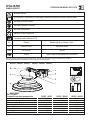 2
2
-
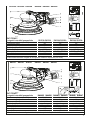 3
3
-
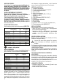 4
4
-
 5
5
-
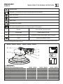 6
6
-
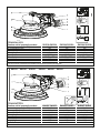 7
7
-
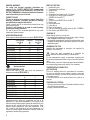 8
8
-
 9
9
-
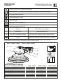 10
10
-
 11
11
-
 12
12
-
 13
13
-
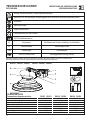 14
14
-
 15
15
-
 16
16
-
 17
17
-
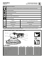 18
18
-
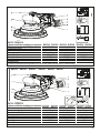 19
19
-
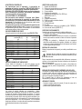 20
20
-
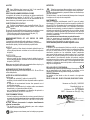 21
21
-
 22
22
-
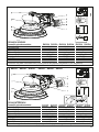 23
23
-
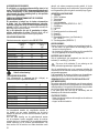 24
24
-
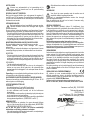 25
25
-
 26
26
-
 27
27
-
 28
28
-
 29
29
-
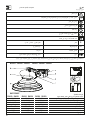 30
30
-
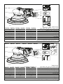 31
31
-
 32
32
-
 33
33
-
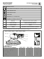 34
34
-
 35
35
-
 36
36
-
 37
37
-
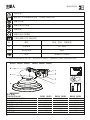 38
38
-
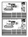 39
39
-
 40
40
-
 41
41
-
 42
42
-
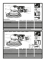 43
43
-
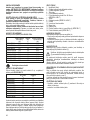 44
44
-
 45
45
-
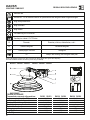 46
46
-
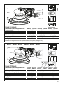 47
47
-
 48
48
-
 49
49
-
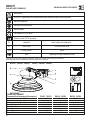 50
50
-
 51
51
-
 52
52
-
 53
53
-
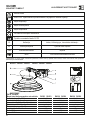 54
54
-
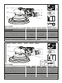 55
55
-
 56
56
-
 57
57
-
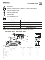 58
58
-
 59
59
-
 60
60
-
 61
61
-
 62
62
-
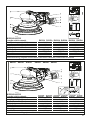 63
63
-
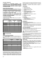 64
64
-
 65
65
-
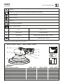 66
66
-
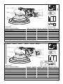 67
67
-
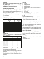 68
68
-
 69
69
-
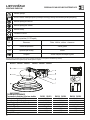 70
70
-
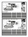 71
71
-
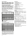 72
72
-
 73
73
-
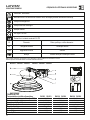 74
74
-
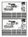 75
75
-
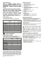 76
76
-
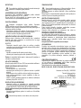 77
77
-
 78
78
-
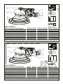 79
79
-
 80
80
-
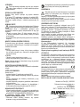 81
81
-
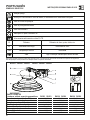 82
82
-
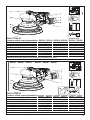 83
83
-
 84
84
-
 85
85
-
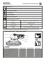 86
86
-
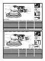 87
87
-
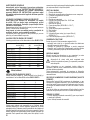 88
88
-
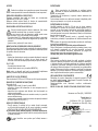 89
89
-
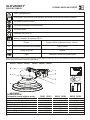 90
90
-
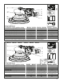 91
91
-
 92
92
-
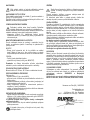 93
93
-
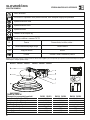 94
94
-
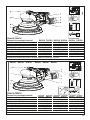 95
95
-
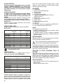 96
96
-
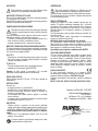 97
97
-
 98
98
-
 99
99
-
 100
100
-
 101
101
-
 102
102
-
 103
103
-
 104
104


Rupes RH356 Manual de utilizare
- Tip
- Manual de utilizare
în alte limbi
- italiano: Rupes RH356 Manuale utente