
INSTRUKCJA OBSŁ UGI
1
PL
DE
RUS
LV
HU
E
RO
CZ
UA
LT
SK
MULTIMETR CYFROWY
DIGITAL MULTIMETER
DIGITALES MULTIMETER
ЦИФРОВОЙ МУЛЬТИМЕТР
ЦИФРОВИЙ МУЛЬТИМЕТР
SKAITMENINIS MULTIMETRAS
CIPARU MULTI-MĒRĪTĀJS
DIGITÁLNÍ MULTIMETR
DIGITÁLNY MULTIMETER
DIGITÁLIS MULTIMÉTER
APART DIGITAL DE MASURAT
MULTIMETRO DIGITAL
YT-73088
GB

INSTRUKCJA OBSŁ UGI
2
DE
1. miernik
2. ekran
3. wybierak
4. przyciski sterujce
5. przycza miernika
6. kable pomiarowe
1. meter
2. display
3. selector
4. control buttons
5. connections of the meter
6. measurement leads
1.
2.
3.
4.
5.
6.
1. matuoklis
2. ekranas
3. parinkties perjungiklis
4. valdymo mygtukai
5. matuoklio lizdai
6. matavimo laidai
1.
2.
3.
4.
5.
6.
1. mrtjs
2. ekrns
3. prsldzjs
4. vadbas pogas
5. mrtja kontakti
6. mršanas vadi
1. mící pístroj
2. displej
3. pepína
4. ovládací tlaítka
5. zdíky mícího pístroje
6. mící vodie
1. merací prístroj
2. displej
3. prepína
4. ovládacie tlaidlá
5. zdierky meracieho prístroja
6. meracie vodie
1. mérmszer
2. kijelz
3. választó kapcsoló
4. vezérl gombok
5. a mérmszer csatlakozói
6. mér kábelek
1. aparat de msurat
2. ecran
3. buton de selectare
4. butoane de control
5. conexiuni aparat de msurat
6. conductori de msurat
1. medidor
2. pantalla
3. selector
4. botones de control
5. conexiones del medidor
6. cables de medición
EROHUSK
CZ
LV
UA
LT
RUS
GB
PL
1. Messgerät
2. Bildschirm
3. Wählschalter
4. Steuertasten
5. Anschlüsse des Messgerätes
6. Messkabel
TOYA S.A. ul. Sotysowicka 13-15, 51-168 Wrocaw, Polska
Rok produkcji:
Production year:
Produktionsjahr:
:
:
Pagaminimo metai:
2012
Ražošanas gads:
Rok výroby:
Rok výroby:
Gyártási év:
Anul produciei utilajului:
Año de fabricación:
PL DE
RUS
LV HU EROCZUA LT SKGB
6
1
2
3
4
5

INSTRUKCJA OBSŁ UGI
3
OCHRONA ŚRODOWISKA
Symbol wskazujcy na selektywne zbieranie zuytego sprztu elektrycznego i elektronicznego. Zuyte urzdzenia elektryczne s surowcami wtórnymi - nie wolno wyrzuca ich do
pojemników na odpady domowe, poniewa zawieraj substancje niebezpieczne dla zdrowia ludzkiego i rodowiska! Prosimy o aktywn pomoc w oszczdnym gospodarowaniu zasobami
naturalnymi i ochronie rodowiska naturalnego przez przekazanie zuytego urzdzenia do punktu skadowania zuytych urzdze elektrycznych. Aby ograniczy ilo usuwanych odpadów
konieczne jest ich ponowne uycie, recykling lub odzysk w innej formie.
UMWELTSCHUTZ
Das Symbol verweist auf ein getrenntes Sammeln von verschlissenen elektrischen und elektronischen Ausrüstungen. Die verbrauchten elektrischen Geräte sind Sekundärrohstoffe – sie
dürfen nicht in die Abfallbehälter für Haushalte geworfen werden, da sie gesundheits- und umweltschädigende Substanzen enthalten! Wir bitten um aktive Hilfe beim sparsamen Umgang
mit Naturressourcen und dem Umweltschutz, in dem die verbrauchten Geräte zu einer Annahmestelle für solche elektrischen Geräte gebracht werden. Um die Menge der zu beseitigenden
Abfälle zu begrenzen, ist ihr erneuter Gebrauch, Recycling oder Wiedergewinnung in anderer Form notwendig.
ОХРАНА ОКРУЖАЮЩЕЙ СРЕДЫ
. – ,
, , !
. , ,
.
ОХОРОНА НАВКОЛИШНЬОГО СЕРЕДОВИЩА
. ,
, , !
, . , , ,
.
APLINKOS APSAUGA
Simbolis nurodo, kad suvartoti elektroniniai ir elektriniai renginiai turi bti selektyviai surenkami. Suvartoti elektriniai rankiai, – tai antrins žaliavos – j negalima išmesti nam kio
atliek konteiner, kadangi savo sudtyje turi medžiag pavojing žmgaus sveikatai ir aplinkai! Kvieiame aktyviai bendradarbiauti ekonomiškame natrali ištekli tvarkyme perduodant
netinkam vartoti rank suvartot elektros rengini surinkimo punkt. Šalinam atliek kiekiui apriboti yra btinas j pakartotinis panaudojimas, reciklingas arba medžiag atgavimas
kitoje perdirbtoje formoje.
VIDES AIZSARDZĪBA
Simbols rda izlietoto elektrisko un elektronisko iekrtu selektvu savkšanu, Izlietotas elektriskas iekrtas ir otrreizjas izejvielas – nevar bt izmestas ar mjsaimniecbas atkritumiem, jo
satur substances, bstamas cilvku veselbai un videi! Ldzam aktvi paldzt saglabt dabisku bagtbu un sargt vdi, pasniegšot izlietoto iekrtu izlietotas elektriskas ierces savkšanas
punkt. Lai ierobežot atkritumu daudzumu, tiem jbt vlreiz izlietotiem, prstrdtiem vai dabtiem atpaka cit form.
OCHRANA ŽIVOTNÍHO PROSTŘEDÍ
Symbol poukazuje na nutnost separovaného sbru opotebovaných elektrických a elektronických zaízení. Opotebovaná elektrická zaízení jsou zdrojem druhotných surovin – je zakázáno
vyhazovat je do nádob na komunální odpad, jelikož obsahují látky nebezpené lidskému zdraví a životnímu prostedí! Prosíme o aktivní pomoc pi úsporném hospodaení s pírodními zdroji
a ochran životního prostedí tím, že odevzdáte použité zaízení do sbrného stediska použitých elektrických zaízení. Aby se omezilo množství odpad, je nevyhnutné jejich optovné
využití, recyklace nebo jiná forma regenerace.
OCHRANA ŽIVOTNÉHO PROSTREDIA
Symbol poukazuje na nutnos separovaného zberu opotrebovaných elektrických a elektronických zariadení. Opotrebované elektrické zariadenia sú zdrojom druhotných surovín – je
zakázané vyhadzova ich do kontejnerov na komunálny odpad, nakoko obsahujú látky nebezpené udskému zdraviu a životnému prostrediu! Prosíme o aktívnu pomoc pri hospodárení
s prírodnými zdrojmi a pri ochrane životného prostredia tým, že opotrebované zariadenia odovzdáte do zberného strediska opotrebovaných elektrických zariadení. Aby sa obmedzilo
množstvo odpadov, je nutné ich opätovné využitie, recyklácia alebo iné formy regenerácie.
KÖRNYEZETVÉDELEM
A használt elektromos és elektronikus eszközök szelektív gyjtésére vonatkozó jelzés: A használt elektromos berendezések újrafelhasználható nyersanyagok – nem szabad ket a háztar-
tási hulladékokkal kidobni, mivel az emberi egészségre és a környezetre veszélyes anyagokat tartalmaznak! Kérjük, hogy aktívan segítse a természeti forrásokkal való aktív gazdálkodást
az elhasznált berendezéseknek a tönkrement elektromos berendezéseket gyjt pontra történ beszállításával. Ahhoz, hogy a megsemmisítend hulladékok mennyiségének csökkentése
érdekében szükséges a berendezések ismételt vagy újra felhasználása, illetve azoknak más formában történ visszanyerése.
PROTEJAREA MEDIULUI
Simbolul adunrii selective a utilajelor electrice i electronice. Utilajele electrice uzate sunt materie prim repetat – este interzis aruncarea lor la gunoi, deoarece conin substane
duntoare sntii omeneti cât duntoare mediului! V rugm deci s avei o atitudine activ în ceace privete gospodrirea economic a resurselor naturale i protejarea mediului
natural prin predarea utilajului uzat la punctul care se ocup de asemenea utilaje electrice uzate. Pentru a limita cantitile deeurilor eliminate este necesar întrebuinatrea lor din nou ,
prin recyklind sau recuperarea în alt form.
PROTECCIÓN DEL MEDIO AMBIENTE
El símbolo que indica la recolección selectiva de los aparatos eléctricos y electrónicos usados. ¡Aparatos eléctricos y electrónicos usados son reciclados – se prohíbe tirarlos en contene-
dores de desechos domésticos, ya que contienen sustancias peligrosas para la salud humana y para el medio ambiente! Les pedimos su participación en la tarea de la protección y de los
recursos naturales y del medio ambiente, llevando los aparatos usados a los puntos de almacenamiento de aparatos eléctricos usados. Con el fin de reducir la cantidad de los desechos,
es menester utilizarlos de nuevo, reciclarlos o recuperarlos de otra manera.
ENVIRONMENTAL PROTECTION
Correct disposal of this product: This marking shown on the product and its literature indicates this kind of product mustn’t be disposed with household wastes at the end of its working
life in order to prevent possible harm to the environment or human health. Therefore the customers is invited to supply to the correct disposal, differentiating this product from other types
of refusals and recycle it in responsible way, in order to re - use this components. The customer therefore is invited to contact the local supplier office for the relative information to the
differentiated collection and the recycling of this type of product.
PL DE
RUS
LV HU EROCZUA LT SKGB

INSTRUKCJA OBSŁ UGI
4
Napicie stae
Direct voltage
Gleichspannung
Nuolatini tampa
Nemaingais spriegums
Naptí stejnosmrné
Napätie jednosmerné
Egyenfeszültség
Tensiune de curent contnuu
Tensiones constantes
Napicie przemienne
Alternating voltage
Wechselspannung
Kintamoji tampa
Maispriegums
Naptí stídavé
Napätie striedavé
Váltakozó feszültség
Tensiune de curent alternativ
Tensiones alternantes
Prd stay
Direct current
Gleichstrom
Nuolatini tampa
Ldzstrva
Proud stejnosmrný
Prúd jednosmerný
Egyenáram
Curent contnuu
Corriente directa
Prd przemienny
Alternating current
Wechselstrom
Kintamoji tampa
Maistrva
Proud stídavý
Prúd striedavý
Váltóáram
Curent alternativ
Corriente alterna
Rezystancja
Resistance
Widerstand
Varža
Rezistence
Odpor
Odpor
Ellenállás
Rezisten
omic
Resistencia
Pojemno
Capacity
Kapazität
Talpa
Tilpums
Kapacita
Kapacita
Kapacitás
Capacitatea
Capacidad
PL DE
RUS
LV HU EROCZUA LT SKGB
U
D.C.
0-600V
I
D.C.
0-10A
U
A.C.
0-600V
I
A.C.
0-10A
R
0-60
M Ω
C
0-4000
μF
Kontrola diod
Diode tests
Diodenkontrolle
Diod kontrol
Diodes prbaude
Kontrola diod
Kontrola diód
Diódaellenrzés
Verificarea diodelor
Control de diodos
Temperatura
Temperature
Temperatur
Temperatra
Temperatra
Teplota
Teplota
Hmérséklet
Temperatura
Temperatura
wbudowany brzczyk
built-in buzzer
eingebaute Summer
taisytas zirzeklis
iebvts signalizators
zabudovaný bzuák
zabudovaný bzuák
beépített berreg
semnal fonic
alarma integrada
T
-20
O
÷
+1000
O
C
Czstotliwo
Frequency
Frequenz
Dažnis
Frekvence
Frekvence
Frekvencia
Frekvencia
Frecvena
Frecuencia
f
9,999MHz
max
Wspóczynnik wypenienia
Pulse-duty factor
Einschaltdauer
Impulso laiko ir signalo trukms santykis
Samra koeficients
initel plnní (stída)
inite plnenia (strieda)
Kitöltési tényez
Raport ciclic
Factor de duración del impulso
5% ÷95%
True
RMS
Pomiar rzeczywistej wartoci skutecznej sygnau
Measurement of the root square value of the signal
Die Messung der quadratische Wert des Signals
Matavimo signalo root kvadratin reikšm
Mršana saku eometrisk vrtba signla
Mení hodnoty koene námstí signálu
Meranie hodnoty korea námestí signálu
Mérése a root tér értékét a jel
De msurare a valorii rdcina ptrat a semnalului
Medición del valor de la raíz cuadrada de la señal

INSTRUKCJA OBSŁ UGI
5
PLPL
CHARAKTERYSTYKA PRZYRZĄDU
Miernik wielofunkcyjny jest cyfrowym przyrzdem pomiarowym przeznaczonym do wykonywania pomiarów rónych wielkoci elek-
trycznych. W przypadku niektórych wielkoci pomiarowych miernik potrafi sam dobra zakres w zalenoci od wyniku pomiaru. Miernik
mierzy rzeczywist warto skuteczn sygnaów okresowo zmiennych (true RMS), co pozwala na dokadne okrelenie tej wartoci,
równie dla sygnaów o przebiegu innym ni sinusoidalny.
Przed rozpoczęciem pracy miernikiem należy przeczytać całą instrukcję i zachować ją.
Miernik posiada obudow z tworzywa sztucznego, wywietlacz ciekokrystaliczny, przecznik zakresów pomiarowych. W obudowie
zainstalowane s gniazda pomiarowe oraz gniazdo do sprawdzania tranzystorów. Miernik wyposaony jest w przewody pomiarowe
zakoczone wtykami. Miernik sprzedawany jest bez baterii zasilajcej.
UWAGA! Oferowany miernik nie jest przyrzdem pomiarowym w rozumieniu ustawy „Prawo o pomiarach”
DANE TECHNICZNE
Wywietlacz: LCD 4 cyfry - maksymalny wywietlany wynik: 9999
Czstotliwo próbkowania: okoo
3 razy na sekund
Oznakowanie przecienia: wywietlany symbol „OL”
Oznakowanie polaryzacji: wywietlany znak „-” przed wynikiem pomiaru
Bateria: 6F22; 9 V
Temperatura pracy: 0 ÷ 40 st. C; przy wzgldnej wilgotnoci <75%
Temperatura przechowywania: -10 st. C ÷ +50 st. C; przy wzgldnej wilgotnoci <85%
Wymiary zewntrzne: 185 x 86 x 44 mm
Waga: ok. 380 g
UWAGA! Zabronione jest mierzenie wartości elektrycznych przekraczających maksymalny zakres pomiarowy miernika.
Parametr
Napicie stae Napicie przemienne Prd stayPrd przemienny
dla zakresu 600 mV: R
IN
> 1000 M;
pozostae zakresy: R
IN
= 10 M
R
IN
= 10 M; f
IN
= 40 ÷ 1000 Hz U
AB
400 mV f
IN
= 40 ÷ 400Hz
Nr. katalogowy Zakres Rozdzielczo Dokadno Zakres Rozdzielczo Dokadno Zakres Rozdzielczo Dokadno Zakres Rozdzielczo Dokadno
YT-73088
600 mV 0,1 mV ±(0,8% + 5) 6 V 0,1 mV ±(1,6% + 10) 600 A 0,1 A
±(1,0% + 7)
600 A 0,1 A
±(1,8% + 10)
6 V 1 mV ±(0,5% + 5) 60 V 1 mV
±(1,5% + 10)
6000 A1 A 6000 A1 A
60 V 10 mV ±(0,8% + 5)
600 V 10 mV
60 mA 0,01 mA 60 mA 0,01 mA
600 V 0,1 V ±(1,0% + 7)
600 mA 0,1 mA 600 mA 0,1 mA
6A 0,001 A
±(1,5% + 7)
6A 0,001 A
±(2,5% + 10)
10 A 0,01 A 10 A 0,01 A
Uwagi
Zabezpieczenie przecieniowe:
zakres 400 mV: 250 V; pozostae
zakresy: 600 V
Zabezpieczenie przecieniowe: 600 V
Zabezpieczenie przecieniowe: bezpiecznik 630 mA/690 V, szybki; zakres 10
A: 10A/690V, szybki - pomiar prdu > 2A , czas pomiaru < 10 sek. w interwaach
> 15 min.
Parametr Rezystancja Pojemno (pomiar relatywny) Czstotliwo Kontrola diod
Nr. katalogowy Zakres Rozdzielczo Dokadno Zakres Rozdzielczo Dokadno Zakres Rozdzielczo Dokadno Warunki pomiaru
YT-73088
600 0,1 ±(1,0% + 5) 40 nF 0,01 nF ±(3,5% + 20) 9,999 Hz 0,001 Hz
±(1,0% + 5)
I
F
= 0,8 mA U
R
= 3 V
6 k 1
±(0,8% + 5)
400 nF 0,1 nF ±(2,5% + 5) 99,99 Hz 0,01 Hz
60 k 10 4 F 0,001 F ±(3,5% + 5) 999,9 Hz 0,1 Hz
600 k 0,1 k 40 F 0,01 F ±(4,0% + 5) 9,999 kHz 0,001 kHz
6 M 1 k ±(1,5% + 5) 400 F 0,1 F ±(5,0% + 5) 99,99 kHz 0,01 kHz
60 M 10 k ±(3,0% + 10) 4000 F1 F nie okrelono
999,9 kHz 0,1 kHz
9,999 MHz 1 kHz nie okrelono
Uwagi
Napicie obwodu otwartego okoo 0,25 V; Za-
bezpieczenie przecieniowe 250 V d.c./a.c.
Dokadno nie uwzgldnia bdu
spowodowanego pojemnoci miernika i
przewodów pomiarowych. Dla zakresów
400 nF naley od wyniku odj pojem-
no miernika i przewodów pomiarowych
Zakres napi sygnau wejciowego: 1 V rms
÷ 20 V rms; stosowa automatyczny dobór
zakresu pomiarowego

INSTRUKCJA OBSŁ UGI
6
PL
Parametr Temperatura Wspóczynnik wypenienia
Nr. katalogowy Zakres Rozdzielczo Dokadno Zakres Rozdzielczo Dokadno
YT-73088
-20
O
C ÷ 0
O
C 0,1
O
C ±(6,0% + 5
O
C)
5% ÷ 95% 0,1% ±(2,0% + 7)
0
O
C ÷ +400
O
C 0,1
O
C ±(1,5% + 4
O
C)
+400
O
C ÷ +1000
O
C1
O
C ±(1,8% + 5
O
C)
-4
O
F ÷ +32
O
F 0,1
O
F ±(6,0% + 9
O
F)
+32
O
F ÷ +752
O
F 0,1
O
F ±(1,5% + 7,2
O
F)
+752
O
F ÷ +1832
O
F1
O
F ±(1,8% + 9
O
F)
Uwagi
Bezpiecznik 630mA/690V. Dokadno nie zawiera bdu termopary. Podana dokadno
obowizuje dla zmian temperatury otoczenia nie wikszych ni ± 1
O
C, w przypadku
zmian temperatury otoczenia ± 5
O
C - podan dokadno osiga si po 1 godzinie.
Zakres napi sygnau wejciowego: 4 Vp-p ÷ 10 Vp-p; 4 Hz - 1
KHz, stosowa automatyczny dobór zakresu pomiarowego
Dokadno: ± (% wskazania + waga najmniej znaczcej cyfry)
EKSPLOATACJA MULTIMETRU
UWAGA! W celu ochrony przed niebezpieczestwem poraenia prdem elektrycznym przed otworzeniem obudowy przyrzdu naley
odczy od niego przewody pomiarowe oraz wyczy miernik.
Instrukcje bezpieczeństwa
Nie pracowa miernikiem w atmosferze o zbyt wysokiej wilgotnoci, obecnoci oparów toksycznych lub atwopalnych, w atmosferze
wybuchowej. Przed kadym uyciem sprawdzi stan miernika oraz przewodów pomiarowych, w przypadku zauwaenia jakichkolwiek
usterek nie wolno przystpowa do pracy. Uszkodzone przewody wymieni na nowe pozbawione wad. W przypadku jakichkolwiek
wtpliwoci naley skontaktowa si z producentem. Podczas pomiaru przewody kocówki pomiarowe trzyma tylko za izolowan
cz. Nie dotyka placami miejsc pomiaru lub niewykorzystanych gniazd miernika. Przed zmiana mierzonej wielkoci naley od-
czy przewody pomiarowe. Nigdy nie przystpowa do prac konserwacyjnych bez upewnienia si, e od miernika zostay odczone
przewody pomiarowe, a sam miernik zosta wy
czony.
Wymiana baterii
Multimetr wymaga zasilania przez baterię 9V typu 6F22. Zaleca si stosowanie baterii alkalicznych. W celu zamontowania baterii
naley otworzy pokryw umieszczon na spodzie miernika przekrcajc pokrto w stron symbolu otwartej kódki. Podczy bateri
zgodnie z oznakowaniem zacisków, zamkn pokryw i przekrci pokrto. Jeeli zostanie wywietlony symbol baterii, oznacza
to, e naley wymieni baterie na now. Ze wzgldu na dokadno pomiarów zaleca si wymian baterii jak najszybciej od chwili
wywietlenia si symbolu baterii.
Wymiana bezpiecznika
W przyrzdzie zastosowano dwa bezpieczniki aparaturowe 630mA/690V; prd wyczalny 20kA; o szybkiej charakterystyce;
(Ø10x38mm); 10A/690V; prd wyczalny 20kA; (Ø10x38mm) o szybkiej charakterystyce. W razie uszkodzenia wymieni bezpiecznik
na nowy o identycznych parametrach elektrycznych. W tym celu naley otworzy obudow miernika. Najpierw nale
y wyj bateri
zasilajc, a nastpnie po wycigniciu miernika z gumowej osony, odkrci wkrty umieszczone na spodniej stronie miernika.
Otworzy obudow, a nastpnie zachowujc zasady bezpieczestwa wymieni bezpiecznik na nowy.
Przycisk „Hold/Light”
Przycisk „Hold/Light” suy do zachowania na wywietlaczu zmierzonej wartoci. Przyciniecie przycisku spowoduje, e aktualnie
wywietlana warto pozostanie na wywietlaczu, nawet po zakoczeniu pomiaru. W celu powrotu do trybu pomiaru naley ponownie
nacisn przycisk „Hold/Light”. Dziaanie funkcji jest sygnalizowane liter „H” widoczn w wywietlaczu. W celu wczenia podwietla-
nia naley nacisn i przytrzyma przycisk przez ok. 2 sekundy. Wyczenie podwietlenia wymaga ponownego nacinicia przycisku
i przytrzymania przez ok. 2 sekundy.
Przycisk „Hz/Duty”
Je
eli wybierak jest ustawiony w pozycji „Hz/Duty”, przycisk suy do wyboru pomiaru czstotliwoci „Hz” lub cyklu pracy „%”. Wybrany
tryb jest sygnalizowany przez wywietlenie odpowiedniego symbolu.
Przycisk „Rel/USB”
Przycisk umoliwia pomiar wartoci wzgldnej. Funkcja jest dostpny dla kadej pozycji wybieraka oprócz pomiarów czstotliwoci,
cyklu pracy oraz testowana przewodzenia lub diod. Przycinicie przycisku „REL” podczas pomiaru spowoduje wyzerowanie wywie-
tlacza i przyjcie widocznej przed wywietlaniem wartoci jako poziomu odniesienia. Nowy pomiar pokae rónic pomidzy wartoci
zmierzon, a zachowan wartoci odniesienia. Ponowne nacinicie przycisku spowoduje powrót do trybu normalnego pomiaru.
Dziaanie funkcji jest sygnalizowane wywietleniem symbolu trójkta.
Naciniecie i przytrzymanie przycisku przez ok. 2 sekundy umoliwia komunikacj multimetru z komputerem poprzez doczony kabel
USB. W celu instalacji oprogramowania do obsugi multimetru naley przeczyta i zastosowa si do instrukcji zawartej na pycie CD
doczonej do produktu.

INSTRUKCJA OBSŁ UGI
7
PL
Przycisk „Max/Min”
Przycisk suy do uruchomienia trybu rejestrowania wartoci minimalnych i maksymalnych. W celu uruchomienia trybu pracy naley
nacisn i przytrzyma przycisk przez ok. 1 sekund. Po uruchomieniu trybu multimetr rozpoczyna rejestrowanie wywietlanych
wyników. Za kadym razem gdy wskazywana warto spadnie poniej minimalnej zarejestrowanej lub wzronie powyej maksymalnej
zarejestrowanej, nowe wartoci s zapisywane w pamici multimetru. Przyciskajc przycisk mona wywietla na zmian minimaln i
maksymaln zapisan warto, co jest sygnalizowane wywietleniem odpowiedniego wskanika. Wyjcie z trybu zapisu maksymalnej
i minimalnej wartoci naley przycisn przycisk „Max/Min” i przytrzyma go przez ok. 1 sekund.
Uwaga! Dla wielkoci, w których miernik jest w stanie automatycznie dobra zakres pomiarowy, wejcie w tryb rejestracji wartoci
maksymalnej i minimalnej spowoduje wyczenie automatycznego doboru zakresu pomiarowego. Naley wczeniej wybra waciwy
zakres pomiarowy.
Przycisk „Range”
Przycisk su
y do rcznej zmiany zakresu pomiarowego danej wielkoci. Po naciniciu z wywietlacza znika znak „AUTO”. Kolejne
nacinicia przycisku przecza zakres wg kolejnoci podanej w tabeli. Przytrzymanie przycisku przez ok. 1 sekund przywraca
automatyczny wybór zakresu.
P
RZYCISK „SELECT”
Przycisk suy do wyboru mierzonej wielkoci. Przy pomiarze natenia prdu umoliwia wybór pomidzy pomiarem prdu staego
i prdu przemiennego. Przy pomiarze temperatury umoliwia wybór jednostki pomidzy stopniem Celsjusza i Farenheita, a take
umoliwia wybór pomidzy testem diod i testem przewodzenia.
Podłączanie przewodów testowych
Z wtyczek przewodów cign pokrywy zabezpieczajce i podczy zgodnie z wytycznymi zawartymi w instrukcji. Nastpnie ci-
gn osony czci pomiarowej i przystpi do pomiarów.
Wbudowany brzęczyk
Miernik posiada wbudowany brzczyk, który wydaje krótki sygna dwikowy po kadym naciniciu klawisza, jako potwierdzenie,
e nacinicie odnioso skutek. Brzczyk wyda sygna dwikowy w nast
pujcych sytuacjach: w przypadku pomiaru prdu w trybie
automatycznego doboru zakresu jeli miernik zmieni zakres z 6 A na 10 A. W trakcie zmiany zakresu na wywietlaczu pojawi si
symbol „OL”. Brzczyk wyda 5 sygnaów dwikowych na minut przed automatycznym wyczeniem miernika oraz jeden dugi sygna
dwikowy zaraz przed automatycznym wyczeniem. Miernik wycza si samoczynnie po upywie 15 minut od ostatniego wcinicia
przycisku lub zmiany pozycji wybieraka. Jeeli multimetr jest podczony do komputera miernik nie wyczy si samoczynnie.
WYKONYWANIE POMIARÓW
W zalenoci od aktualnego pooenia przecznika zakresów na wywietlaczu zostan wywietlone cztery cyfry znaczce. Gdy
zachodzi potrzeba wymiany baterii multimetr informuje o tym wywietlajc symbol baterii na wywietlaczu. W przypadku, gdy na
wywietlaczu przed mierzona wartoci pojawi si znak „-” oznacza to, e mierzona wartoci ma odwrotn polaryzacj w stosunku do
pod
czenia miernika. W przypadku, gdy na wywietlaczu pojawi si tylko symbol „OL” Oznacza to przekroczenie zakresu pomiaro-
wego, w takim wypadku naley zmieni zakres pomiarowy na wyszy. W przypadku pomiarów wielkoci o nieznanej wartoci naley
nastawi miernik w tryb „AUTO” pozwalajc aby sam okreli najlepszy zakres pomiarowy.
UWAGA! Nie wolno dopuścić, aby zakres pomiarowy miernika był mniejszy niż mierzona wartość. Może to doprowadzić do
zniszczenia miernika oraz porażenia prądem elektrycznym.
Prawidłowe podłączenie przewodów to:
Przewód czerwony do gniazda oznaczonego „VHz”, „A/mA” lub „10A”.
Przewód czarny do gniazda oznaczonego „COM”
W celu uzyskania jak najwikszej dokadnoci pomiarowej naley zapewni optymalne warunki pomiarowe. Temperatura otoczenia w
zakresie od 18 st. C do 28 st. C oraz wilgotno wzgldna powietrza <75 %
Przykład wyznaczania dokładności
Dokadno: ± (% wskazania + waga najmniej znaczcej cyfry)
Pomiar napicia staego: 1,396 V
Dokadno: ±(0,8% + 5)
Obliczenie bdu:1,396 x 0,8% + 5 x 0,001 = 0,011168 + 0,005 = 0,016168
Wynik pomiaru: 1,396 V ± 0,016 V
Pomiar napięcia
Podczy przewody pomiarowe do gniazd oznaczonych „VHz” i „COM”. Przecznikiem zakresów ustawi w pozycji pomiaru na-
picia staego lub napicia przemiennego. Przewody pomiarowe doczy równolegle do obwodu elektrycznego i odczyta wynik

INSTRUKCJA OBSŁ UGI
8
PL
pomiaru napicia. Nigdy nie mierzy napicia wyszego ni 600 V. Moe to doprowadzi do zniszczenia miernika i poraenia prdem
elektrycznym.
Pomiar natężenia prądu
W zalenoci od spodziewanej wartoci mierzonego natenia prdu przewody pomiarowe podczy do gniazda „A/mA” i „COM”
lub do gniazda „10A” i „COM”. Wybra pokrtem odpowiedni zakres pomiarowy, a przyciskiem „Select” rodzaj mierzonego prdu.
Maksymalne natenie mierzonego prdu w gniedzie „A/mA” moe wynosi 600 mA w przypadku pomiaru prdu wyszego ni 600
mA, naley podczy przewód do gniazda „10A”. Pomiaru prdów wyszych ni 2 A nie moe przekracza 10 sekund, po czym naley
zastosowa co najmniej 15 minut przerwy przed nastpnym pomiarem. Jest zabronione przekraczanie maksymalnych dla danego
gniazda wartości prądów i napięć
. Przewody pomiarowe naley wczy szeregowo do badanego obwodu elektrycznego, wybra
zakres i rodzaj mierzonego prdu przecznikiem i odczyta wynik pomiaru. Trzeba rozpocz pomiary od wybrania maksymalnego
zakresu pomiarowego. W celu uzyskania dokadniejszych wyników pomiaru mona zmieni zakres pomiarowy.
Pomiar rezystancji
Podczy przewody pomiarowe do gniazd oznaczonych „VHz” i „COM” przecznik zakresów ustawi w pozycji pomiaru rezystancji.
Kocówki pomiarowe przyoy do zacisków mierzonego elementu i odczyta wynik pomiaru. W celu uzyskania dokadniejszych wyni-
ków pomiaru, zmieni zakres pomiarowy. Jest absolutnie zabroniony pomiar rezystancji elementów, przez które przepływa prąd
elektryczny. Dla pomiarów wartoci wikszych ni 1M pomiar moe zaj kilka sekund zanim ustabilizuje si wynik, to normalna
reakcja w przypadku pomiarów duych rezystancji.
Przed przyoeniem kocówek pomiarowych do mierzonego elementu, na wywietlaczu jest widoczny symbol „OL”.
Pomiar pojemności
Podczy przewody pomiarowe do gniazd oznaczonych „VHz” i „COM”, przecznik zakresów ustawi
w pozycji pomiaru pojem-
noci. Upewni si, e kondensator przed pomiarem zosta rozadowany. Nigdy nie mierzyć pojemności naładowanego konden-
satora, może to doprowadzić do uszkodzenia miernika i porażenia prądem elektrycznym. Nacisn przycisk „Rel/USB”, tak
aby na wywietlaczu, pojawi si symbol trójkta oznaczajcy pomiar wartoci wzgldnej. Pozwoli to zredukowa wpyw pojemnoci
przewodów pomiarowych na wynik pomiaru. W przypadku pomiaru kondensatorów o duej pojemnoci pomiar moe trwa okoo 30
sekund zanim ustabilizuje si wynik. W przypadku pomiarów pojemnoci wikszej lub równej 4000 F, wywietlacz pokae symbol
„OL”. Maksymalny odczyt jaki moe si pojawi przy pomiarze pojemnoci wynosi „3999”.
Pomiar częstotliwości
Podczy przewody pomiarowe do gniazd oznaczonych „VHz” i „COM”, prze
cznik zakresów ustawi w pozycji „Hz/Duty”. Przyci-
skiem „Select” wybra pomiar czstotliwoci, na wywietlaczu widoczny jest symbol „Hz”. Odczyta wynik pomiaru na wywietlaczu.
W przypadku pomiaru czstotliwoci napicie mierzonego sygnau powinno si zawiera w przedziale od 1 V rms do 20 V rms. W
przypadku pomiaru sygnau o napiciu wyszym ni 20 V rms, dokadno pomiaru wykracza poza zakres podany w tabeli.
Test diod
Podczy przewody pomiarowe do gniazd oznaczonych „VHz” i „COM” wybierak ustawi na symbolu diody. Przyciskiem „Select”
wybra testowanie diod, na wywietlaczu widoczny jest symbol diody. Kocówki pomiarowe przykadamy do wyprowadze diody
w kierunku przewodzenia i w kierunku zaporowym. Jeli dioda jest sprawna, przy diodzie podczonej w kierunku przepustowym
odczytamy spadek napicia na tej diodzie wyraony w V. W przypadku podczenia w kierunku zaporowym na wywietlaczu zostanie
wywietlony symbol „OL”. Diody sprawne cechuje maa rezystancja w kierunku przewodzenia oraz dua rezystancja w kierunku
zaporowym. Jest absolutnie zabronione testowanie diod, przez które przepływa prąd elektryczny.
Test przewodzenia
Podczy przewody pomiarowe do gniazd oznaczonych „VHz” i „COM”. Przyciskiem „Select” wybra testowanie przewodzenia, na
wy
wietlaczu widoczny jest symbol brzczyka. W przypadku wykorzystania miernika do pomiaru przewodzenia, wbudowany brzczyk
wyda sygna dwikowy za kadym razem, gdy mierzona rezystancja spadnie poniej 20 . Powyej 150 brzczyk nie bdzie
wydawa sygnau dwikowego. Jest absolutnie zabronione testowanie przewodzenia, w obwodach, przez które przepływa
prąd elektryczny.
Pomiar temperatury
Podczy koce przewodów termopary do gniazd oznaczonych „A/mA” i „COM”. Wybierak miernika ustawi w pooenie „TEMP”.
Termopar przyoy do mierzonego obiektu. Termopara doczona do produktu umoliwia pomiar tylko do 250
O
C. W celu pomiaru
wyszych temperatur naley zaopatrzy si w termopar przeznaczon do pomiaru wyszych temperatur. Naley stosowa termopary
typu K.
Pomiar współczynnika wypełnienia
Podczy przewody pomiarowe do gniazd oznaczonych „VHz” i „COM”. Wybierak miernika ustawi w pooenie „Hz/Duty” Przyci-
skiem „Hz/Duty” wybra pomiar wspóczynnika wypenienia, na wywietlaczu widoczny jest symbol „%”. Odczyta wynik pomiaru na
wywietlaczu. Napicie mierzonego sygnau musi si zawiera w zakresie od 4 Vp-p do 10 Vp-p, a czstotliwo sygnau powinna
si zawiera w przedziale 4Hz do 1kHz. Jeli parametry mierzonego sygnau wykraczaj poza podany zakres, dokadno wykracza

INSTRUKCJA OBSŁ UGI
9
PL
poza zakres podany w tabeli.
Vp-p - oznacza napicie midzy szczytowymi punktami sygnau.
KONSERWACJA I PRZECHOWYWANIE
Miernik wyciera mikk szmatk. Wiksze zabrudzenia usuwa za pomoc lekko wilgotnej szmatki. Nie zanurza miernika w wodzie
lub innej cieczy. Do czyszczenia nie stosowa rozpuszczalników, rodków rcych lub ciernych. Naley dba o czysto styków mier-
nika i przewodów pomiarowych. Styki przewodów pomiarowych czyci szmatk lekko nasczon alkoholem izopropylowym. W celu
przeczyszczenia styków miernika, naley miernik wyczy oraz wymontowa bateri. Odwróci miernik i delikatnie nim potrzsn,
tak aby wiksze zabrudzenia wydostay si ze zczy miernika. Wacik baweniany na patyczku lekko nasczy alkoholem izopropylo-
wym i wyczyci kady styk. Poczeka, a alkohol odparuje, nastpnie zamontowa bateri
. Miernik naley przechowywa w suchym
pomieszczeniu w dostarczonym opakowaniu jednostkowym.

10
PLGB
OPERATING MANUAL
PROPERTIES OF THE DEVICE
The all-purpose meter is a digital measurement instrument designed to measure distinct electrical quantities. In case of certain meas-
urement quantities the meter adapts an adequate range depending on the result of the measurement.
Before using the meter, read the whole manual and keep it.
The meter has a plastic housing, a liquid crystal display and a measurement range selector. The housing is equipped with measure-
ment sockets and a transistor test socket. The meter is equipped with measurement cables with plugs. The meter is sold without a
battery.
ATTENTION! The meter is not a measurement device as it is construed within the „Measurement Law”.
TECHNICA DATA
Display: 4-digit LCD – maximum displayed result: 9999
Sampling frequency: approximately 3 times per second
Overload signalling: „OL” is displayed
Polarization signalling: symbol „-” is displayed before the result of the measurement
Battery: 6F22; 9 V
Working temperature: 0 ÷ 40°C at the relative humidity <75%
Storage temperature: -10°C ÷ +50°C; at the relative humidity <85%
External dimensions: 185 x 86 x 44 mm
Weight: approximately 380 g
ATTENTION! It is prohibited to measure electrical quantities exceeding the maximum measurement range of the meter.
Parameter
Direct voltage Alternating voltage Direct current Alternating current
for the range 600 mV: R
IN
> 1000 M;
other ranges: R
IN
= 10 M
R
IN
= 10 M; f
IN
= 40 ÷ 1000 Hz U
AB
400 mV f
IN
= 40 ÷ 400Hz
Catalogue number Range Resolution Precision Range Resolution Precision Range Resolution Precision Range Resolution Precision
YT-73088
600 mV 0.1 mV ±(0.8% + 5) 6 V 0.1 mV ±(1.6% + 10) 600 A 0.1 A
±(1.0% + 7)
600 A 0.1 A
±(1.8% + 10)
6 V 1 mV ±(0.5% + 5) 60 V 1 mV
±(1.5% + 10)
6000 A1 A 6000 A1 A
60 V 10 mV ±(0.8% + 5)
600 V 10 mV
60 mA 0.01 mA 60 mA 0.01 mA
600 V 0.1 V ±(1.0% + 7)
600 mA 0.1 mA 600 mA 0.1 mA
6A 0.001 A
±(1.5% + 7)
6A 0.001 A
±(2,5% + 10)
10 A 0.01 A 10 A 0.01 A
Remarks
Overload protection: range 400 mV:
250 V; other ranges: 600 V
Overload protection: 600 V
Overload protection: fuse 630 mA/690 V, quick-break; range 10 A: 10A/690V,
quick-break - measurement of the current > 2A , duration of measurement <
10 s in intervals > 15 min.
Parameter Resistance Capacitance (relative measurement) Frequency Diode test
Catalogue number Range Resolution Precision Range Resolution Precision Range Resolution Precision Measurement conditions
YT-73088
600 0.1 ±(1.0% + 5) 40 nF 0.01 nF ±(3,5% + 20) 9,999 Hz 0.001 Hz
±(1.0% + 5)
I
F
= 0.8 mA U
R
= 3 V
6 k 1
±(0.8% + 5)
400 nF 0.1 nF ±(2,5% + 5) 99,99 Hz 0.01 Hz
60 k 10 4 F 0.001 F ±(3,5% + 5) 999,9 Hz 0.1 Hz
600 k 0.1 k 40 F 0.01 F ±(4,0% + 5) 9,999 kHz 0.001 kHz
6 M 1 k ±(1.5% + 5) 400 F 0.1 F ±(5,0% + 5) 99,99 kHz 0.01 kHz
60 M 10 k ±(3,0% + 10) 4000 F1 F not specified
999,9 kHz 0.1 kHz
9,999 MHz 1 kHz not specified
Remarks
Open circuit current approximately 0.25
V; Overload protection 250 V d.c./a.c.
The precision value does not include the er-
ror caused by the capacitance of the meter
and the measurement cables. For ranges
400 nF it is necessary to deduct from the
result the capacitance of the meter and the
measurement cables
Range of the input signal voltage: 1 V rms ÷
20 V rms; use the automatic measurement
range selection

11
PLGB
OPERATING MANUAL
Parameter Temperature Pulse-duty factor
Catalogue number Range Resolution Precision Range Resolution Precision
YT-73088
-20
O
C ÷ 0
O
C 0.1
O
C ±(6,0% + 5
O
C)
5% ÷ 95% 0.1% ±(2,0% + 7)
0
O
C ÷ +400
O
C 0.1
O
C ±(1.5% + 4
O
C)
+400
O
C ÷ +1000
O
C1
O
C ±(1.8% + 5
O
C)
-4
O
F ÷ +32
O
F 0.1
O
F ±(6,0% + 9
O
F)
+32
O
F ÷ +752
O
F 0.1
O
F ±(1.5% + 7,2
O
F)
+752
O
F ÷ +1832
O
F1
O
F ±(1.8% + 9
O
F)
Remarks
Fuse 630mA/690V. The precision value does not include the error of the thermoele-
ment. The indicated precision applies to the changes in the ambient temperature
which do not exceed ± 1
O
C; in case of changes in the ambient temperature
amounting to ± 5
O
C the indicated precision is achieved after one hour.
Range of the input signal voltage: 4 Vp-p ÷ 10 Vp-p; 4 Hz - 1 KHz,
use the automatic measurement range selection
Precision: ± (% of the indication + weight of the least significant digit)
OPERATION OF THE MULTIMETER
ATTENTION! In order to protect from electric shock before the housing of the device is opened, disconnect the measurement cables
and turn the meter off.
Safety instructions
Do not operate the meter in the presence of an excessive humidity, toxic or inflammable vapours and in explosive atmosphere. Before
each use check the conditions of the meter and the measurement cables. If any damage is detected, it is prohibited to operate the
device. Damaged cables must be replaced. In case of any doubts, consult the manufacturer. During measurements keep the measure-
ment cables and leads by the insulated parts. Do not touch the places of measurement or the sockets of the meter which are not being
used. Before the measured quantity is modified, disconnect the measurement cables. Do not realize any maintenance tasks without
making sure the measurement cables have been disconnected from the meter, and the meter itself has been turned off.
Replacement of the battery
The multimeter is powered with a 9V 6F22 battery. It is recommended to use alkaline batteries. In order to install a battery, open the
cover at the bottom of the device, turning the knob towards the open padlock symbol. Connect the battery in accordance with the
marking of the terminals, close the cover and turn the knob. If the battery symbol is displayed, the battery must be replaced. For the
sake of precision of measurements, it is recommended to replace the battery as soon as possible once the symbol of battery has
been displayed.
Replacement of the fuse
The device is equipped with two 630mA/690V quick-break equipment fuses; breaking current 20kA; (Ø10x38mm); 10A/690V; breaking
current 20kA; (Ø10x38mm). If the fuse is damaged, it must be replaced with a new one of the same electrical parameters. To do so,
open the housing of the meter. First remove the battery and having removed the meter from the rubber protection remove the screws
at the bottom of the device. Open the housing and observing the safety recommendations replace the fuse.
Button „Hold/Light”
The „Hold/Light” button permits to hold the measured value in the display. If the button is pushed the displayed value will remain in the
display even when the measurement is finished. In order to return to the measurement mode push the „Hold/Light” button again. Acti-
vation of the function is indicated with an „H” in the display. In order to turn the backlight on push and hold the button for approximately
2 seconds. In order to turn the backlight off push the button again and hold it for approximately 2 seconds.
Button „Hz/Duty”
If the selector is in the „Hz/Duty” position, then the button permits to select frequency measurements „Hz” or the cycle of operation „%”.
The selected mode is signalled in the display with the corresponding symbol.
Button „Rel/USB”
The purpose of the button is to measure the relative value. The function is available for every position of the selector apart from the
measurements of frequency, cycle of operation and conduction or diode tests. If the „REL” button is pushed during the measurement,
the display is reset and the previously displayed value is adopted as a reference level. A new measurement will indicate the difference
between the measured value and the saved reference value. If the button is pushed again, the device will return to the normal mode
of measurement. The function is signalled in the display with a triangle.
If the button is pushed and held for approximately 2 seconds, communication between the multimeter and a computer is activated
through the supplied USB cable.

12
PLGB
OPERATING MANUAL
Button „Max/Min”
The purpose of the button is to activate the mode of minimum and maximum values registration. In order to activate the mode push and
hold the button for approximately 1 second. Once the mode has been activated, the multimeter starts to register the displayed results.
Each time the indicated value drops below the minimum registered value or rises above the maximum registered value, new values
are registered in the memory of the multimeter. Pushing the button permits to display alternately the minimum and maximum register
value, which is signalled in the display with a corresponding indicator. To leave the maximum and minimum register mode push the
„Max/Min” button and hold it for approximately 1 second.
Attention! In case of quantities for which the meter may automatically select the measurement range, activation of the minimum and maxi-
mum register value will deactivate the automatic measurement range selection. Select previously the adequate measurement range.
Button „Range”
The purpose of the button is to manually change the measurement range for the given quantity. When it is pushed „AUTO” disappears
from the display. If it is pushed again the range is changed in the sequence indicated in the table. If the button is held for approximately
1 second, then the automatic range selection is restored.
Button „Select”
The purpose of the button is to select the quantity to be measured. In case of current intensity measurements it permits to choose be-
tween measurements of direct and alternating current. In case of a measurement of temperature it permits to switch between Celsius
and Fahrenheit and to choose between a diode test and conduction test.
Connection of the test leads
Remove the protection caps from the plugs and connect them in accordance with the instructions. Then remove the protections of the
measurement part and proceed to measurements.
Internal buzzer
The meter is equipped with an internal buzzer, which emits a short sound every time a button is pressed to confirm it. The buzzer
will emit a sound in the following situations: in case of a measurement of current in the automatic range selection mode, if the meter
switches the range from 6 A to 10 A. While switching the range „OL” is indicated in the display. The buzzer will emit five sound signals
per minute before the meter turns off automatically and one long sound signal immediately before the meter turns off automatically. If
the selector remains in the same position and no other button is pushed, the meter will turn out automatically after approximately 15
minutes. If the multimeter is connected to a computer, the meter will not turn off automatically.
MEASUREMENTS
Depending on the actual position of the range switch four significant digits will be displayed. If it is necessary to replace the battery the
multimeter indicates this displaying the battery symbol. If before the measured value the “-” symbol is displayed then the measured
value has an opposite polarization in relation to the connection of the meter. If only „OL” is displayed, then the measurement range is
exceeded, and it is necessary to increase the measurement range. In case of measurements of quantities of unknown values, set the
meter in the „AUTO” mode, so that the best measurement range is determined automatically.
ATTENTION! The measurement range of the meter must not be lower than the measured value. It might damage the meter
and cause an electric shock.
The correct connection of the leads:
The red lead must be connected to the socket marked as „VHz”, „A/mA” or „10A”.
The black lead must be connected to the socket marked as „COM”
In order to ensure the highest possible precision of the measurements the optimum measurement conditions must be observed: ambi-
ent temperature between 18°C and 28°C and relative humidity <75 %
Determination of precision
Precision: ± % of the indication + weight of the least significant digit
Measurement of the direct voltage: 1.396 V
Precision: ± (0.8% + 5)
Calculation of the error: 1.396 x 0.8% + 5 x 0.001 = 0.011168 + 0.005 = 0.016168
Result of the measurement: 1.396 V ± 0.016 V
Measurements of voltage
Connect the measurement cables to the sockets marked as „VHz” and “COM”. Switch the range selector to the position of the
measurement of the direct voltage or alternating voltage. Connect the measurement cables in parallel to the electric circuit and read
the result of the measurements of the voltage. Do not ever measure a voltage exceeding 600 V, which might damage the meter and
cause an electric shock.

13
PLGB
OPERATING MANUAL
Measurement of intensity of the current
Depending on the expected value of the measured intensity of the current connect the measurement cables to the socket marked
as „A/mA” and „COM” or to the socket marked as „10A” and „COM”. Use the selector to choose the adequate measurement range
and the „Select” button to choose the kind of the measured current. Maximum intensity of the current measured through the socket
marked as „A/mA” may amount to 600 mA, and in case it is higher than 600 mA, the cable must be connected to the „10A” socket.
The duration of the measurements of currents exceeding 2 A must not exceed 10 seconds, and it is required to wait at least 15 minutes
before the next measurement. The maximum current and voltage values of the sockets must not be exceeded. Connect the
measurement cables in series to the tested electric circuit, select the range and kind of the current and read the result of the measure-
ment. The first stage of the measurements is to select the maximum measurement range. In order to ensure more precise results of
the measurement you may change the measurement range.
Measurements of resistance
Connect the measurement cables to the sockets marked as „VHz” and „COM”; switch the range selector to the position of the meas-
urement of resistance. Place the measurements leads at the terminals of the measured element and read the result. In order to ensure
more precise results of the measurement the measurement range may be changed if required. It is strictly prohibited to measure
the resistance of live elements. In case of measurements of values exceeding 1M the measurement may take a couple of seconds
before the result is stable, which is a normal reaction during measurements of high resistances.
Before the measurements leads are placed at the element to be measured, the „OL” symbol is displayed.
Measurement of capacitance
Connect the measurement cables to the sockets marked as „VHz” and „COM”; switch the range selector to the position of the meas-
urement of capacitance. Make sure the capacitor was discharged before the measurement. Do not ever measure the capacitance
of a charged capacitor, since it might damage the meter and cause an electric shock. Push the „Rel/USB” button, after which
a triangle will be displayed indicating a relative value measurement. It will permit to reduce the influence of measurement cables ca-
pacitance upon the result of the measurement. In case of measurements of high-capacitance condensers the measurement may last
approximately 30 seconds before the result is stable. In case of measurements of capacities amounting to 4000 F or higher, the „OL”
will be displayed. The maximum result of the capacitance measurements that may be displayed is „3999”.
Measurements of frequency
Connect the measurement cables to the sockets marked as „VHz” and „COM”; switch the range selector to the „Hz/Duty” position.
Use the „Select” button to choose measurements of frequency, after which „Hz” will be displayed. Read the result of the measurement
in the display. In case of measurements of frequency, the voltage of the measured signal should be between 1 V rms and 20 V rms. In
case of measurements of a signal whose voltage exceeds 20 V rms, the precision of the measurement exceeds the range indicated
in the table.
Diode test
Connect the measurement cables to the sockets marked as „VHz” and „COM”, and switch the selector to the diode symbol. Use the
„Select” button select diode test, after which the diode symbol will be displayed. Place the measurement leads at the diode terminals
in the conduction direction and the reverse direction. If the diode is functioning correctly, then at the diode connected in the forward
direction we will read the voltage drop for this diode expressed in V. In case the diode is connected in the reverse direction the display
will read „OL. Correctly functioning diodes show a low resistance in the forward direction and a high resistance in the reverse direction.
It is strictly prohibited to test live diodes.
Conduction test
Connect the measurement cables to the sockets marked as „VHz” and „COM”. Use the „Select” button to select conduction test. The
buzzer symbol will be displayed. In case the meter is used for conduction measurements, the internal buzzer will emit sound each time
the measured resistance drops below 20 . Above 150 the buzzer will not sound. It is strictly prohibited to test the conduction
of live circuits.
Measurement of temperature
Connect the thermoelement leads to the sockets marked as „A/mA” and „COM”. Switch the selector of the meter to „TEMP”. Put the
thermoelement to the measured object. The thermoelement supplied with the device permits to realise measurements only up to 250
O
C. In order to measure higher temperatures it is necessary to purchase a thermoelement that permits to measure higher tempera-
tures. It is required to use thermoelements type K.
Measurement of the pulse-duty factor
Connect the measurement cables to the sockets marked as „VHz” and „COM”. Switch the selector of the meter to „Hz/Duty” Use
the „Hz/Duty” button to select the measurement of the pulse-duty factor. The symbol „%” will be displayed. Read the result of the
measurement in the display. The voltage of the measured signal should be between 4 Vp-p and 10 Vp-p, and the frequency of the
signal should be between 4Hz and 1kHz. If the parameters of the measured signal exceed the indicated range, the precision exceeds
the range indicated in the table.
Vp-p – voltage between the peak points of the signal.

14
PLGB
OPERATING MANUAL
MAINTENANCE AND STORAGE
Clean the meter with a soft cloth. Remove heavy soiling with a damp cloth. Do not submerge the meter in water or any other liquid.
Do not use solvents, caustic or abrasive substances to clean the meter. Make sure the contacts of the meter and the measurement
cables are clean. Clean the terminals of the measurement cables with a cloth slightly soaked with isopropyl alcohol. In order to clean
the contacts of the meter turn the meter off and remove the battery. Turn the meter round and shake it slightly to remove major impuri-
ties from the contacts of the meter. Soak slightly a cotton swab in isopropyl alcohol and clean each contact. Wait until the alcohol has
evaporated and replace the battery. Store the meter in a dry place in the provided case.

D
15
BEDIENUNGSANLEITUNG
CHARAKTERISTIK DES MESSGERÄTES
Das Vielfachmessgerät ist ein digitales Messinstrument, das für die Ausführung von Messungen verschiedener elektrischer Größen
vorgesehen ist. Bei einigen Messgrößen ist das Messinstrument in der Lage, sich den Messbereich in Abhängigkeit vom Messergebnis
selbst zu wählen.
Vor Beginn der Arbeiten mit diesem Messgerät muss man die gesamte Anleitung durchlesen und auch einhalten.
Das Messgerät hat ein Gehäuse aus Kunststoff, eine Flüssigkristallanzeige sowie einen Schalter für die Messbereiche. Im Gehäuse
sind Messbuchsen sowie eine Buchse zum Überprüfen der Transistoren installiert. Das Messgerät ist mit Messleitungen ausgerüstet,
die am Ende einen Stecker haben. Das Messgerät wird ohne Batterie für die Stromversorgung verkauft.
HINWEIS! Das angebotene Messgerät ist kein Messinstrument im Sinne des Gesetzes „Gesetz über Messungen”
TECHNISCHE DATEN
Anzeige: LCD 4 Ziffern – maximal anzuzeigendes Ergebnis: 1999
Abtastfrequenz: zirka 3 Mal pro Sekunde
Kennzeichnung der Überlastung: das Symbol „OL” wird angezeigt.
Kennzeichnung der Polarisation: das Zeichen „-” wird vor dem Messergebnis angezeigt
Batterie: 6F22; 9 V
Betriebstemperatur: 0 ÷ 40 °C; bei relativer Feuchtigkeit von <75%
Lagertemperatur: -10 °C ÷ +50 °C; bei relativer Feuchtigkeit von <85%
Außenabmessungen: 185 x 86 x 44 mm
Gewicht: ca. 380 g
ACHTUNG! Das Messen von elektrischen Werten, die den maximalen Messbereich des Messgerätes überschreiten, ist ver-
boten.
Parameter
Gleichspannung Wechselspannung Gleichstrom Wechselstrom
für den Bereich 600 mV: R
IN
> 1000 M;
sonstige Bereiche: R
IN
= 10 M
R
IN
= 10 M; f
IN
= 40 ÷ 1000 Hz U
AB
400 mV f
IN
= 40 ÷ 400Hz
Katalog-Nr. Bereich Auflösung Genauigkeit Bereich Auflösung Genauigkeit Bereich Auflösung Genauigkeit Bereich Auflösung Genauigkeit
YT-73088
600 mV 0,1 mV ±(0,8% + 5) 6 V 0,1 mV ±(1,6% + 10) 600 A 0,1 A
±(1,0% + 7)
600 A 0,1 A
±(1,8% + 10)
6 V 1 mV ±(0,5% + 5) 60 V 1 mV
±(1,5% + 10)
6000 A1 A 6000 A1 A
60 V 10 mV ±(0,8% + 5)
600 V 10 mV
60 mA 0,01 mA 60 mA 0,01 mA
600 V 0,1 V ±(1,0% + 7)
600 mA 0,1 mA 600 mA 0,1 mA
6A 0,001 A
±(1,5% + 7)
6A 0,001 A
±(2,5% + 10)
10 A 0,01 A 10 A 0,01 A
Bemerkungen
Überlastschutz: Bereich 400 mV: 250 V ;
sonstige Bereiche: 600 V
Überlastschutz: 600 V
Überlastschutz: Sicherung 630 mA/690 V, flink; Bereich 10 A: 10A/690 V, flink
- Strommessung > 2A , Messzeit < 15 Sek. in Intervallen > 15 Min.
Parameter Widerstand Kapazität (relative Messung) Frequenz Kontrolle der Dioden
Katalog-Nr. Bereich Auflösung Genauigkeit Bereich Auflösung Genauigkeit Bereich Auflösung Genauigkeit Messbedingungen
Katalog-Nr.
600 0,1 ±(1,0% + 5) 40 nF 0,01 nF ±(3,5% + 20) 9,999 Hz 0,001 Hz
±(1,0% + 5)
I
F
= 0,8 mA U
R
= 3 V
6 k 1
±(0,8% + 5)
400 nF 0,1 nF ±(2,5% + 5) 99,99 Hz 0,01 Hz
60 k 10 4 F 0,001 F ±(3,5% + 5) 999,9 Hz 0,1 Hz
600 k 0,1 k 40 F 0,01 F ±(4,0% + 5) 9,999 kHz 0,001 kHz
6 M 1 k ±(1,5% + 5) 400 F 0,1 F ±(5,0% + 5) 99,99 kHz 0,01 kHz
60 M 10 k ±(3,0% + 10) 4000 F1 F nicht definiert
999,9 kHz 0,1 kHz
9,999 MHz 1 kHz nicht definiert
Bemerkungen
Spannung des offenen Stromkreises ca.
0,25 V; Überlastsschutz 250 V d.c./a.c.
Die Genauigkeit berücksichtigt nicht
den Fehler, der durch die Kapazität des
Messgerätes und der Messleitungen
hervorgerufen wird. Für die Bereiche 400
nF muss man vom Ergebnis die Kapazität
des Messgerätes und der Messleitungen
abziehen.
Spannungsbereich des Eingangssignals: 1
V rms ÷ 20 V rms; automatische Wahl des
Messbereiches verwenden

16
D
BEDIENUNGSANLEITUNG
Parameter Temperatur Einschaltdauer
Katalog-Nr. Bereich Auflösung Genauigkeit Bereich Auflösung Genauigkeit
YT-73088
-20
O
C ÷ 0
O
C 0,1
O
C ±(6,0% + 5
O
C)
5% ÷ 95% 0,1% ±(2,0% + 7)
0
O
C ÷ +400
O
C 0,1
O
C ±(1,5% + 4
O
C)
+400
O
C ÷ +1000
O
C1
O
C ±(1,8% + 5
O
C)
-4
O
F ÷ +32
O
F 0,1
O
F ±(6,0% + 9
O
F)
+32
O
F ÷ +752
O
F 0,1
O
F ±(1,5% + 7,2
O
F)
+752
O
F ÷ +1832
O
F1
O
F ±(1,8% + 9
O
F)
Bemerkungen
Sicherung 630mA/690V. Die Genauigkeit enthält nicht den Fehler des Thermoele-
ments. Die angegebene Genauigkeit gilt für Änderungen der Umgebungstemperatur
von nicht größer als ± 1
O
C, bei Änderungen der Umgebungstemperatur von ± 5
O
C
wird die angegebene Genauigkeit erst nach 1 Stunde erreicht.
Spannungsbereich des Eingangssignals: 4 Vp-p ÷ 10 Vp-p; 4 Hz
– 1 KHz, automatische Wahl des Messbereiches verwenden
Genauigkeit: ± % der Anzeige + Wichtigkeit der am wenigsten bedeutenden Ziffer
NUTZUNG DES MULTIMETERS
HINWEIS! Zum Schutz vor der Gefahr eines elektrischen Stromschlags muss man vor dem Öffnen des Messgerätegehäuses die
Messleitungen vom Gerät trennen und das Messgerät ausschalten.
Sicherheitshinweise
Das Messgerät darf nicht in freier Atmosphäre mit zu hoher Feuchtigkeit, bei vorhandenen toxischen oder leicht brennbaren Dämpfen
bzw. in einer explosiven Atmosphäre arbeiten. Vor jedem Gebrauch ist der Zustand des Messgerätes und der Messleitungen zu
überprüfen. Wenn irgendwelche Mängel bemerkt werden, darf man mit den Messarbeiten nicht beginnen. Die beschädigten Leitungen
sind gegen neue, fehlerfreie auszutauschen. Wenn doch noch irgendwelche Zweifel bestehen, muss man sich mit dem Hersteller in
Verbindung setzen. Während der Messung dürfen die Enden der Messleitung nur am isolierten Teil gehalten werden. Ebenso sind
die Messstellen oder die ungenutzten Buchsen des Messgerätes nicht mit den Fingern zu berühren. Auch vor einer Änderung der zu
messenden Größe muss man die Messleitungen abtrennen. Bitte beachten Sie, dass man vor der Aufnahme von Wartungsarbeiten
sich davon überzeugt, ob die Messleitungen vom Messgerät getrennt und das Messgerät ausgeschaltet wurde.
Batteriewechsel
Das Multimeter erfordert eine Stromversorgung durch eine Batterie für 9V vom Typ 6F22, wobei die Verwendung alkalischer Bat-
terien empfohlen wird. Um die Batterie zu montieren, muss man die Abdeckung auf der unteren Seite des Messgerätes öffne, wobei
die Stellschraube in die Richtung des Symbols eines Vorhängeschlosses zu drehen ist. Danach ist die Batterie entsprechend der
Klemmenkennzeichnung anzuschließen, die Abdeckung zu schließen und die Stellschraube anzudrehen. Wenn das Batteriesymbol
angezeigt wird, dann bedeutet dies, dass ein Batteriewechsel notwendig ist. In Bezug auf die Genauigkeit der Messungen wird ein
schnellstmöglicher Batteriewechsel empfohlen, nach dem das Batteriesymbol angezeigt wurde.
Austausch der Sicherung
Im Messgerät wurden zwei Apparatesicherungen 630mA/690V, Ausschaltstrom 20kA, mit flinker Charakteristik;
(Ø 10x38mm); 10A/690V; Ausschaltstrom 20kA; (Ø 10x38mm); mit flinker Charakteristik verwendet. Im Falle einer Beschädigung ist
die Sicherung gegen eine neue mit identischen elektrischen Parametern auszutauschen. Zu diesem Zweck muss man das Gehäuse
des Messgerätes öffnen und Batterie für die Stromversorgung herausnehmen. Nach dem Herausnehmen des Messgerätes aus der
Gummihülle sind die Schrauben auf der unteren Seite des Messgerätes abzudrehen, das Gehäuse zu öffnen und unter Einhaltung der
Sicherheitsbestimmungen erfolgt dann der Wechsel der Sicherungen gegen neue.
Taste „HOLD/Light”
Die Taste „HOLD/Light” dient zum Halten des gemessenen Wertes auf der Anzeige. Das Drücken der Taste bewirkt, dass der aktuell
angezeigte Wert auf der Anzeige verbleibt, und das sogar nach dem Ende der Messung. Zwecks Rückkehr zum Messbetrieb muss
man die Taste „HOLD/Light” erneut drücken. Die Aktivität dieser Funktion wird durch den auf der Anzeige sichtbaren Buchstaben
„H“ signalisiert. Zum Einschalten des Ausleuchtens der Anzeige muss man die Taste ca. 2 Sekunden lang drücken und halten. Das
Ausschalten der Beleuchtung erfordert das erneute Drücken und Halten über 2 Sekunden lang.
Taste „Hz/Duty”
Wenn der Wählschalter auf die Position „Hz/Duty” gestellt wird, dann dient diese Taste zur Wahl der Frequenzmessung „Hz” oder des
Betriebszyklus „%”. Die gewählte Betriebsart wird durch das Aufleuchten des entsprechenden Symbols signalisiert.
Taste „Rel/USB”
Die Taste ermöglicht die Messung des relativen Wertes. Diese Funktion ist für jede Position des Wählschalters, außer für die Messung
der Frequenz, des Betriebszyklus und des Leitungs- oder Diodentests, zugänglich. Das Drücken der Taste „REL” während der Mes-
sung bewirkt die Nullstellung der Anzeige und die Annahme eines vor dem Aufleuchten sichtbaren Wertes als Bezugsniveau. Die neue
Messung zeigt die Differenz zwischen dem gemessenen Wert und dem gespeicherten Bezugswert. Ein erneutes Drücken der Taste

D
17
BEDIENUNGSANLEITUNG
bewirkt die Rückkehr zum Normalbetrieb der Messung. Die Aktivität der Funktion wird durch das Aufleuchten eines Dreiecksymbols
signalisiert.
Wird die Taste ca. 2 Sekunden lang gedrückt und gehalten, ermöglicht man dadurch die Kommunikation des Multimeters mit dem
Computer, und zwar über das beigefügt USB-Kabel.
Taste „Max/Min”
Mit dieser Taste wird das Registrieren der Minimal- und Maximalwerte gestartet. Zur Inbetriebnahme dieser Betriebsfunktion muss
man die Taste für ca. 1 Sekunde drücken und halten. Nach dem Starten der Betriebsart beginnt das Multimeter mit der Registrie-
rung der angezeigten Werte. Jedes Mal, wenn der angezeigte Wert unter den minimalen fällt oder er steigt über den maximalen
abgespeicherten Wert, werden die neuen Werte im Speicher des Multimeters aufgezeichnet. Mit dem Drücken der Taste kann man
abwechselnd den minimalen und maximalen abgespeicherten Wert anzeigen, was durch die Anzeige einer entsprechenden Kennziffer
signalisiert wird. Um aus der Betriebsart der Aufzeichnung des minimalen und maximalen Wertes herauszugehen, muss man die Taste
„Max/Min” drücken und sie ca. 1 Sekunde lang halten.
Hinweis! Für die Größen, bei denen das Messgerät in der Lage ist, automatisch den Messbereich zu wählen, bewirkt der Übergang
in die Betriebsart der Registrierung eines minimalen und maximalen Wertes das Abschalten der automatischen Wahl des Messberei-
ches. Man muss deshalb vorher den richtigen Messbereich wählen.
Taste „Range”
Die Taste dient zur manuellen Änderung des Messbereiches einer gegebenen Größe. Nach dem sie gedrückt wurde verschwindet von
der Anzeige das Zeichen „AUTO“. Das weitere Drücken dieser Taste schaltet den Bereich entsprechend der in der Tabelle angegebe-
nen Reihenfolge um. Wird die Taste ca. 1 Sekunde lang gehalten, kehrt man wieder zur automatischen Wahl des Bereiches zurück.
Taste „Select”
Diese Taste dient zur Wahl der zu messenden Größe. Bei einer Stromstärkemessung ermöglicht sie die Wahl zwischen einer Gleich-
strom- oder Wechselstrommessung. Bei einer Temperaturmessung dagegen wählt sie die Maßeinheit zwischen Grad Celsius und
Fahrenheit. Die Taste ermöglicht auch die Wahl zwischen einem Dioden- oder Leitungstest.
Anschließen der Testleitungen
Die Schutzhüllen sind von den Leitungssteckern abzuziehen und entsprechend den in der Anleitung enthaltenen Richtlinien anzu-
schließen. Danach ist die Abdeckung des Messteiles herunterzuziehen und mit den Messungen zu beginnen.
Eingebauter Summer
Im Messgerät wurde ein Summer eingebaut, der nach jedem Drücken der Taste ein kurzes Tonsignal abgibt, und zwar als Bestäti-
gung, dass das Drücken wirksam war. Das Tonsignal des Summers ertönt in folgenden Situationen: bei einer Messung des Stromes
mit automatischer Wahl des Messbereiches, wenn das Messgerät den Bereich von 6A auf 10A verändert. Während der Bereichsän-
derung erscheint auf der Anzeige das Symbol „OL“. Der Summer gibt 5 Tonsignale pro Minute, bevor das Messgerät automatisch
ausgeschaltet wird, und ein langes Tonsignal kurz vor dem automatischen Ausschalten. Das Messgerät schaltet sich nach Ablauf
von 15 Minuten ab dem letzten Drücken der Taste oder einer Änderung der Position des Wählschalters automatisch ab. Wenn das
Multimeter an einen Computer angeschlossen ist, dann schaltet es sich nicht selbsttätig aus.
AUSFÜHRUNG DER MESSUNGEN
In Abhängigkeit von der aktuellen Stellung des Messbereichschalter werden auf der Anzeige vier bedeutende Ziffern angezeigt. Wenn
die Notwendigkeit für einen Batteriewechsel besteht, informiert das Multimeter darüber und zeigt das Batteriesymbol auf der Anzeige.
In dem Fall, wenn auf der Anzeige vor dem Messwert das Zeichen „-” erscheint, dann bedeutet dies, dass der Messwert eine im
Verhältnis zum Anschluss des Messgerätes umgekehrte Polarisation hat. Wenn auf der Anzeige nur das Symbol „OL“ erscheint, wird
eine Überschreitung des Messbereiches angezeigt. In dem Fall muss man den Messbereich wechseln und einen höheren wählen. Bei
den Messungen von Größen mit unbekanntem Wert ist das Messgerät auf die Betriebsart „AUTO“ einzustellen und zu ermöglichen,
dass es selbst den besten Messbereich bestimmt.
ACHTUNG! Es darf nicht zugelassen werden, dass der eingestellte Messbereich des Messgerätes kleiner als der zu messen-
de Wert ist, da dies zu einer Zerstörung des Messgerätes und zu einem elektrischen Stromschlag führen kann.
Die Leitungen sind wie folgt richtig angeschlossen:
Die rote Leitung in die mit „VHz”, „A/mA „10A” gekennzeichnete Buchse;
die schwarze Leitung in die Buchse „COM“.
Um die größte Messgenauigkeit zu erreichen, muss man auch optimale Messbedingungen gewährleisten, d.h. die Umgebungstempe-
ratur im Bereich von 18 °C bis 28 °C und die relative Luftfeuchtigkeit <75 %.
Bespiel zur Bestimmung der Genauigkeit
Genauigkeit: ± % der Anzeige + Wichtigkeit der am wenigsten bedeutenden Ziffer
Messung der Gleichspannung: 1,396 V

18
D
BEDIENUNGSANLEITUNG
Genauigkeit: ±(0,8% + 5)
Fehlerberechnung:1,396 x 0,8% + 5 x 0,001 = 0,011168 + 0,005 = 0,016168
Messergebnis: 1,396 V ± 0,016 V
Spannungsmessung
Die Messleitungen sind an die mit „VHz” und „COM” bezeichneten Buchsen anzuschließen. Der Messbereichsschalter ist wieder-
um auf die Position der Gleich- oder Wechselspannungsmessung einzustellen. Die Messleitungen werden parallel zum elektrischen
Stromkreis angeschlossen und das Ergebnis der Spannungsmessung abgelesen. Eine höhere Spannung als 600 V darf nie gemessen
werden. Dies kann zur Zerstörung des Messgerätes und zu einem elektrischen Stromschlag führen.
Stromstärkemessung
In Abhängigkeit von dem erwarteten Wert der zu messenden Stromstärke sind die Messleitungen an die Buchsen „A/mA ” und „COM”
oder „10A” und „COM” anzuschließen. Mit dem Drehschalter ist dann der entsprechende Messbereich und mit der Taste „Select“ die
Stromart für die Messung zu wählen.
Die maximale Stromstärke, die in der Buchse „A/mA ” gemessen werden kann, beträgt 600 mA; bei der Messung eines höheren
Stromes als 600 mA muss man die Leitung an die Buchse „10A” anschließen. Bei einer Strommessung von höher als 2A darf man die
Zeit für die Messung von 10 Sekunden nicht überschreiten, wonach eine Pause von mindestens 15 Minuten bis zur nächsten Messung
einzuhalten ist. Das Überschreiten der für eine gegebene Buchse vorgegebenen maximalen Strom- und Spannungswerte ist
verboten. Die Messleitungen sind in Reihenschaltung zu dem zu prüfenden elektrischen Stromkreis zu bringen, den Bereich und
die Art des zu messenden Stromes mit dem Schalter zu wählen und das Messergebnis abzulesen. Die Messungen müssen immer
mit dem maximalen Messbereich begonnen werden. Um genauere Messergebnisse zu erzielen, kann man dann den Messbereich
verändern.
Widerstandsmessung
Die Messleitungen werden an die Buchsen „VHz ” und „COM” angeschlossen und der Messbereichsschalter auf die Position für
die Widerstandsmessung eingestellt. Die Messenden sind an die Klemmen des zu messenden Elements anzulegen und das Mes-
sergebnis abzulesen. Um genauere Messergebnisse zu erreichen, muss man bei Bedarf den Messbereich verändern. Die Wider-
standsmessung an Elementen, durch die elektrischer Strom fließt, ist absolut verboten. Die Messung von Werten größer als
1M kann einige Sekunden dauern, bevor sich das Ergebnis stabilisiert. Das ist bei Messungen von großen Widerständen eine ganz
normale Reaktion.
Vor dem Anlegen der Messenden an das zu messende Element erscheint auf der Anzeige das Symbol „OL“.
Kapazitätsmessung
Hierbei sind die Messleitungen an die mit „VHz” und „COM” bezeichneten Buchsen anzuschließen und der Messbereichsschalter
auf die Position für die Kapazitätsmessung zu stellen. Mann muss sich dann davon überzeugen, ob der Kondensator vor der Messung
entladen wurde. Die Kapazität eines aufgeladenen Kondensators darf nicht gemessen werden, denn das kann zur Zerstörung
des Messgerätes oder zu einem elektrischen Stromschlag führen. Die Taste „Rel/USB“ drückt man so, dass auf der Anzeige ein
Dreiecksymbol erscheint, was eine Messung des relativen Wertes bedeutet. Dadurch wird der Einfluss von der Kapazität der Messlei-
tungen auf das Messergebnis reduziert. Bei den Messungen von Kondensatoren mit großer Kapazität kann die Messung bis zu unge-
fähr 30 Sekunden dauern, bis sich das Ergebnis stabilisiert. Bei den Messungen einer Kapazität von größer oder gleich 4000 F wird
auf der Anzeige das Symbol „OL“ angezeigt. Der bei einer Kapazitätsmessung abgelesene maximale Wert kann „3999“ betragen.
Frequenzmessung
Die Leitungsenden sind an die mit „VHz” und „COM” bezeichneten Buchsen anzuschließen und den Messbereichsschalter auf
die Position „Hz/Duty“ zu stellen. Mit der Taste „Select” ist die Frequenzmessung zu wählen, wonach auf der Anzeige das Symbol
„Hz“ sichtbar wird. Das Ergebnis ist dann auf der Anzeige abzulesen. Bei einer Frequenzmessung sollte sich die Spannung des zu
messenden Signals im Intervall von 1 V rms bis 20 V rms bewegen. Erfolgt eine Signalmessung mit einer Spannung von mehr als 20
V rms, überschreitet die Genauigkeit der Messung den in der Tabelle angegebenen Bereich.
Test der Dioden
Die Messleitungen sind an die mit „VHz” und „COM” bezeichneten Buchsen anzuschließen und der Messbereichsschalter auf das
Symbol der Diode einzustellen. Mit der Taste „Select“ ist das Testen der Dioden zu wählen und dann wird auf der Anzeige das Symbol
einer Diode sichtbar. Die Messenden legt man an die Anschlüsse der Diode in Durchlass- und Sperrrichtung. Wenn die Diode funkti-
onsfähig ist, dann kann man bei der in Durchlassrichtung angeschlossenen Diode den Spannungsabfall an dieser Diode, ausgedrückt
in mV, ablesen. Ist die Diode in Sperrrichtung angeschlossen, sieht man auf der Anzeige das Symbol „OL”. Funktionsfähige Dioden
charakterisieren sich durch einen geringen Widerstand in Durchlassrichtung und einen großen Widerstand in der Sperrrichtung. Das
Testen der Dioden, durch die elektrischer Strom fließt, ist absolut verboten.
Testen der Leitfähigkeit
Die Messleitungen sind an die mit „VHz” und „COM” bezeichneten Buchsen anzuschließen. Mit der Taste „Select“ wählt man den
Leitfähigkeitstest und auf der Anzeige wird das Symbol eines Summers sichtbar. Wird das Messgerät für eine Leitfähigkeitsmessung

D
19
BEDIENUNGSANLEITUNG
genutzt, dann gibt der eingebaute Summer jedes Mal, wenn der gemessene Widerstand unter 20 fällt, ein Tonsignal ab. Über 150
ertönt kein Tonsignal vom Summer. Das Testen der Leitfähigkeit in Stromkreisen, durch die Strom fließt, ist absolut verboten.
Temperaturmessung
Die Leitungsenden des Thermoelements sind an die mit „A/mA ” und „COM” bezeichneten Buchsen anzuschließen. Der Wählschalter
des Messgerätes ist in die Stellung „Temp“ zu bringen. Das Thermoelement ist an das zu messende Objekt zu legen. Das dem Produkt
beigefügte Thermoelement ermöglicht nur eine Messung von bis zu 250°C. Zum Messen höherer Temperaturen muss man sich mit
einem Thermoelement ausrüsten, das für die Messung höherer Temperaturen bestimmt ist. Es sind Thermoelemente vom Typ K zu
verwenden.
Messung des Füllungsgrades
Die Messleitungen sind an die mit „VHz” und „COM” bezeichneten Buchsen anzuschließen. Der Wählschalter des Messgerätes
ist auf die Position „Hz/Duty“ zustellen. Mit der Taste „Hz/Duty” ist die Füllungsgradmessung zu wählen, wonach auf der Anzeige
das Symbol „%“ sichtbar wird. Auf der Anzeige ist dann das Ergebnis abzulesen. Die Spannung des gemessenen Signals muss sich
im Bereich von 4 Vp-p bis 10 Vp-p befinden und die Signalfrequenz sollte sich im Intervall von 4Hz bis 1 kHz befinden. Wenn die
Parameter des gemessenen Signals den angegebenen Bereich überschreiten, dann befindet sich auch die Genauigkeit außerhalb
des angegebenen Bereiches.
Vp-p – bezeichnet die Spannung zwischen den Gipfelpunkten des Signals.
WARTUNG UND LAGERUNG
Das Messgerät wird mit einem weichen Lappen abgewischt. Größere Verschmutzungen sind mit einem leicht angefeuchteten Lappen
zu beseitigen. Das Messgerät darf nicht in Wasser oder in eine andere Flüssigkeit getaucht werden. Ebenso dürfen zum Reinigen
keine Lösungsmittel sowie ätzende und abschleifende Mittel zum Einsatz kommen. Man muss stets auf die Sauberkeit der Kontakte
des Messgerätes und der Messleitungen achten. Die Kontakte der Messleitungen sind mit einem Lappen zu reinigen, der leicht mit
Isopropylalkohol getränkt ist. Um die Kontakte des Messgerätes zu reinigen, muss man das Messgerät ausschalten und die Batterie
ausbauen. Dann ist das Messgerät umzudrehen und delikat zu schütteln, so dass die größeren Schmutzteilchen von den Verbindungs-
stellen des Messgerätes herauskommen. Jeder Kontakt ist dann mit einem Wattebauschstäbchen, getränkt mit Isopropylalkohol, zu
reinigen. Vor dem erneuten Einbau der Batterie ist abzuwarten, bis der Alkohol verdampft ist. Das Messgerät muss in einem trockenen
Raum in der mitgelieferten Einheitsverpackung gelagert werden.

RUS
20
ХАРАКТЕРИСТИКА ПРИБОРА
– , -
.
.
Перед началом работы с измерителем необходимо полностью прочитать настоящую инструкцию и сохранить ее.
, , .
, .
. .
! « ”.
ТЕХНИЧЕСКИЕ ПАРАМЕТРЫ
: LCD 4 - : 9999
: 3
:
„OL”
: „-”
: 6F22; 9
: 0 ÷ 40 ºC; <75%
: -10 ºC ÷ +50 ºC; <85%
: 185 x 86 x 44
: 380
ВНИМАНИЕ! Запрещено измерять электрические величины, значение которых превышает допустимый измеритель-
ный диапазон прибора.
600 : R
IN
> 1000 M
: R
IN
= 10 M
R
IN
= 10 M; f
IN
= 40 ÷ 1000 U
AB
400 f
IN
= 40 ÷ 400
-
YT-73088
600 0,1 ±(0,8% + 5) 6 0,1 ±(1,6% + 10) 600 0,1
±(1,0% + 7)
600 0,1
±(1,8% + 10)
6 1 ±(0,5% + 5) 60 1
±(1,5% + 10)
6000 1 6000 1
60 10 ±(0,8% + 5)
600 10
60 0,01 60 0,01
600 0,1 ±(1,0% + 7)
600 0,1 600 0,1
6A 0,001 A
±(1,5% + 7)
6A 0,001 A
±(2,5% + 10)
10 A 0,01 A 10 A 0,01 A
-
:
400 : 250 ;
: 600
: 600
: 630 /690 , ;
10 A: 10A/690, – > 2A , < 10 .
> 15 .
( )
YT-73088
600 0,1 ±(1,0% + 5) 40 0,01 ±(3,5% + 20) 9,999 0,001
±(1,0% + 5)
I
F
= 0,8 U
R
= 3
6 1
±(0,8% + 5)
400 0,1 ±(2,5% + 5) 99,99 0,01
60 10 4 0,001 ±(3,5% + 5) 999,9 0,1
600 0,1 40 0,01 ±(4,0% + 5) 9,999 0,001
6 M 1 ±(1,5% + 5) 400 0,1 ±(5,0% + 5) 99,99 0,01
60 M 10 ±(3,0% + 10)
4000
1
-
999,9 0,1
9,999 M 1
0,25
; 250 -
/
,
-
.
400
:
1 .. ÷ 20 ..; -
Pagina se încarcă...
Pagina se încarcă...
Pagina se încarcă...
Pagina se încarcă...
Pagina se încarcă...
Pagina se încarcă...
Pagina se încarcă...
Pagina se încarcă...
Pagina se încarcă...
Pagina se încarcă...
Pagina se încarcă...
Pagina se încarcă...
Pagina se încarcă...
Pagina se încarcă...
Pagina se încarcă...
Pagina se încarcă...
Pagina se încarcă...
Pagina se încarcă...
Pagina se încarcă...
Pagina se încarcă...
Pagina se încarcă...
Pagina se încarcă...
Pagina se încarcă...
Pagina se încarcă...
Pagina se încarcă...
Pagina se încarcă...
Pagina se încarcă...
Pagina se încarcă...
Pagina se încarcă...
Pagina se încarcă...
Pagina se încarcă...
Pagina se încarcă...
Pagina se încarcă...
Pagina se încarcă...
Pagina se încarcă...
Pagina se încarcă...
Pagina se încarcă...
Pagina se încarcă...
Pagina se încarcă...
Pagina se încarcă...
Pagina se încarcă...
Pagina se încarcă...
Pagina se încarcă...
Pagina se încarcă...
-
 1
1
-
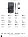 2
2
-
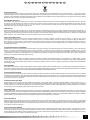 3
3
-
 4
4
-
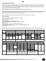 5
5
-
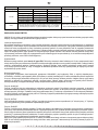 6
6
-
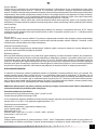 7
7
-
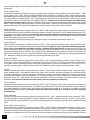 8
8
-
 9
9
-
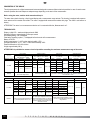 10
10
-
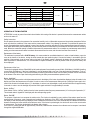 11
11
-
 12
12
-
 13
13
-
 14
14
-
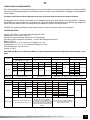 15
15
-
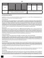 16
16
-
 17
17
-
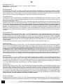 18
18
-
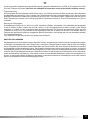 19
19
-
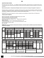 20
20
-
 21
21
-
 22
22
-
 23
23
-
 24
24
-
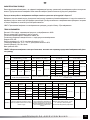 25
25
-
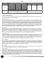 26
26
-
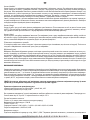 27
27
-
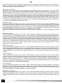 28
28
-
 29
29
-
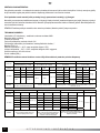 30
30
-
 31
31
-
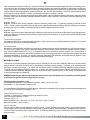 32
32
-
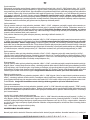 33
33
-
 34
34
-
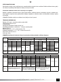 35
35
-
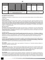 36
36
-
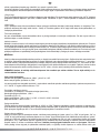 37
37
-
 38
38
-
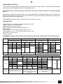 39
39
-
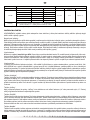 40
40
-
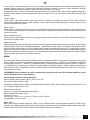 41
41
-
 42
42
-
 43
43
-
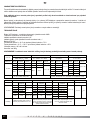 44
44
-
 45
45
-
 46
46
-
 47
47
-
 48
48
-
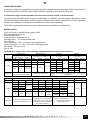 49
49
-
 50
50
-
 51
51
-
 52
52
-
 53
53
-
 54
54
-
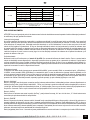 55
55
-
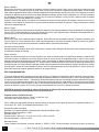 56
56
-
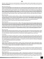 57
57
-
 58
58
-
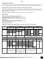 59
59
-
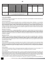 60
60
-
 61
61
-
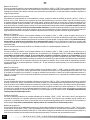 62
62
-
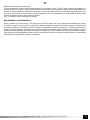 63
63
-
 64
64


în alte limbi
- slovenčina: YATO YT-73088 Používateľská príručka
Alte documente
-
Facom 711A Manualul proprietarului
-
Stanley FMHT0-77421 Manual de utilizare
-
-
Benning MM4 Instrucțiuni de utilizare
-
Emos M0391 Digital Multimeter Manualul utilizatorului
-
 NEO TOOLS 94-003 Manualul proprietarului
-
 NEO TOOLS 94-004 Manualul proprietarului
-
-
Somogyi SMA MAS 830 Manual de utilizare
-

