Makita GA4050 Manual de utilizare
- Categorie
- Unelte electrice
- Tip
- Manual de utilizare

GA4050
GA4050R
GA4550
GA4550R
GA5050
GA5050R
EN Angle Grinder INSTRUCTION MANUAL 6
PL Szlierka kątowa INSTRUKCJA OBSŁUGI 15
HU Sarokcsiszoló HASZNÁLATI KÉZIKÖNYV 25
SK Uhlová brúska NÁVOD NA OBSLUHU 35
CS Úhlová bruska NÁVOD K OBSLUZE 44
UK Кутова шліфувальна
машина ІНСТРУКЦІЯ З
ЕКСПЛУАТАЦІЇ 53
RO Polizor unghiular MANUAL DE INSTRUCŢIUNI 64
DE Winkelschleifer BETRIEBSANLEITUNG 74

1
Fig.1
1
2
Fig.2
Fig.3
1
3
2
Fig.4
2
B
1
A
B
Fig.5
2

2
1
A
C
C
Fig.6
1
2
3
4
Fig.7
2
1
Fig.8
1
2
3
4
Fig.9
Fig.9
3
4
2
1
Fig.10
3
2
1
Fig.11
15°
Fig.12
3

3
2
1
4
Fig.13
16 mm (5/8″) 16 mm (5/8″)
11
44
23
Fig.14
11
44
23
Fig.15
11
44
23
Fig.16
11
44
23
Fig.17
1
Fig.18
1
Fig.19
1
Fig.20
4

1
2
Fig.21
2
5
22
11
12
4
3
5
6
7
8
9
10
1
13
3
14
5
3
Fig.22
5

6ENGLISH
ENGLISH (Original instructions)
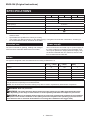
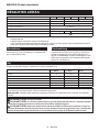
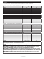
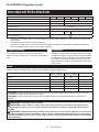
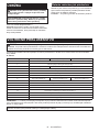
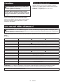
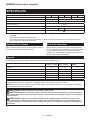
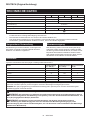
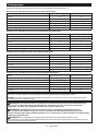
SPECIFICATIONS
Model: GA4050
GA4050R
GA4550
GA4550R
GA5050
GA5050R
Wheel diameter 100 mm (4″) 115 mm (4-1/2″) 125 mm (5″)
Max. wheel thickness 6.4 mm (1/4″) 7.2 mm (9/32″)
Spindle thread M10 M14 or 5/8″
Rated speed (n) 11,000 min-1
Overall length 325 mm
Net weight 2.3 - 2.6 kg
2.4 - 2.8 kg
2.5 - 2.8 kg
Safety class /II
• Due to our continuing program of research and development, the specications herein are subject to change
without notice.
• Specications may dier from country to country.
• The weight may dier depending on the attachment(s). The lightest and heaviest combination, according to
EPTA-Procedure 01/2014, are shown in the table.
Intended use
The tool is intended for grinding, sanding and cutting of
metal and stone materials without the use of water.
Power supply
The tool should be connected only to a power supply of
the same voltage as indicated on the nameplate, and
can only be operated on single-phase AC supply. They
are double-insulated and can, therefore, also be used
from sockets without earth wire.
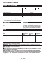
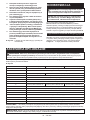
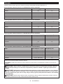
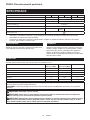
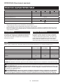
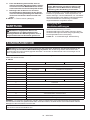
Noise
The typical A-weighted noise level determined according to EN60745-2-3:
Model Sound pressure
level (LpA) : (dB(A)) Sound power level
(LWA) : (dB(A)) Uncertainty (K) :
(dB(A))
GA4050 91 102 3
GA4050R 91 102 3
GA4550 91 102 3
GA4550R 91 102 3
GA5050 91 102 3
GA5050R 91 102 3
NOTE: The declared noise emission value(s) has been measured in accordance with a standard test method and
may be used for comparing one tool with another.
NOTE: The declared noise emission value(s) may also be used in a preliminary assessment of exposure.
WARNING: Wear ear protection.
WARNING: The noise emission during actual use of the power tool can dier from the declared val-
ue(s) depending on the ways in which the tool is used especially what kind of workpiece is processed.
WARNING: Be sure to identify safety measures to protect the operator that are based on an estimation
of exposure in the actual conditions of use (taking account of all parts of the operating cycle such as the
times when the tool is switched o and when it is running idle in addition to the trigger time).

7ENGLISH
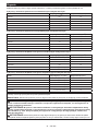
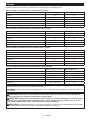
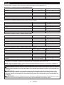
Vibration
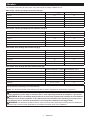
The vibration total value (tri-axial vector sum) determined according to EN60745-2-3:
Work mode: surface grinding with normal side grip
Model
Vibration emission (ah, AG) : (m/s2)
Uncertainty (K) : (m/s2)
GA4050 6.5 1.5
GA4050R 6.5 1.5
GA4550 7.0 1.5
GA4550R 7.0 1.5
GA5050 7.5 1.5
GA5050R 7.5 1.5
Work mode: surface grinding with anti vibration side grip
Model
Vibration emission (ah, AG) : (m/s2)
Uncertainty (K) : (m/s2)
GA4050 5.5 1.5
GA4050R 5.5 1.5
GA4550 7.0 1.5
GA4550R 7.0 1.5
GA5050 8.5 1.5
GA5050R 8.5 1.5
Work mode: disc sanding with normal side grip
Model
Vibration emission (ah, AG) : (m/s2)
Uncertainty (K) : (m/s2)
GA4050 2.5 m/s2 or less 1.5
GA4050R 2.5 m/s2 or less 1.5
GA4550 2.5 1.5
GA4550R 2.5 1.5
GA5050 2.5 m/s2 or less 1.5
GA5050R 2.5 m/s2 or less 1.5
Work mode: disc sanding with anti vibration side grip
Model
Vibration emission (ah, AG) : (m/s2)
Uncertainty (K) : (m/s2)
GA4050 2.5 m/s2 or less 1.5
GA4050R 2.5 m/s2 or less 1.5
GA4550 2.5 m/s2 or less 1.5
GA4550R 2.5 m/s2 or less 1.5
GA5050 2.5 m/s2 or less 1.5
GA5050R 2.5 m/s2 or less 1.5
NOTE: The declared vibration total value(s) has been measured in accordance with a standard test method and
may be used for comparing one tool with another.
NOTE: The declared vibration total value(s) may also be used in a preliminary assessment of exposure.
WARNING: The vibration emission during actual use of the power tool can dier from the declared
value(s) depending on the ways in which the tool is used especially what kind of workpiece is processed.
WARNING: Be sure to identify safety measures to protect the operator that are based on an estimation
of exposure in the actual conditions of use (taking account of all parts of the operating cycle such as the
times when the tool is switched o and when it is running idle in addition to the trigger time).
WARNING: The declared vibration emission value is used for main applications of the power tool. However if
the power tool is used for other applications, the vibration emission value may be dierent.

8ENGLISH
EC Declaration of Conformity
For European countries only
The EC declaration of conformity is included as Annex A
to this instruction manual.
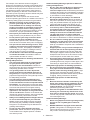
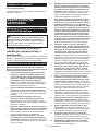
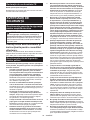
SAFETY WARNINGS
General power tool safety warnings
WARNING: Read all safety warnings, instruc-
tions, illustrations and specications provided
with this power tool. Failure to follow all instructions
listed below may result in electric shock, re and/or
serious injury.
Save all warnings and instruc-
tions for future reference.
The term "power tool" in the warnings refers to your
mains-operated (corded) power tool or battery-operated
(cordless) power tool.
Grinder safety warnings
Safety Warnings Common for Grinding, Sanding,
Wire Brushing, or Abrasive Cutting-O Operations:
1. This power tool is intended to function as a
grinder, sander, wire brush or cut-o tool.
Read all safety warnings, instructions, illus-
trations and specications provided with this
power tool. Failure to follow all instructions listed
below may result in electric shock, re and/or
serious injury.
2. Operations such as polishing are not rec-
ommended to be performed with this power
tool. Operations for which the power tool was not
designed may create a hazard and cause per-
sonal injury.
3. Do not use accessories which are not speci-
cally designed and recommended by the tool
manufacturer. Just because the accessory can
be attached to your power tool, it does not assure
safe operation.
4. The rated speed of the accessory must be at
least equal to the maximum speed marked on
the power tool. Accessories running faster than
their rated speed can break and y apart.
5. The outside diameter and the thickness of your
accessory must be within the capacity rating
of your power tool. Incorrectly sized accessories
cannot be adequately guarded or controlled.
6. Threaded mounting of accessories must
match the grinder spindle thread. For acces-
sories mounted by anges, the arbour hole of
the accessory must t the locating diameter
of the ange. Accessories that do not match the
mounting hardware of the power tool will run out of
balance, vibrate excessively and may cause loss
of control.
7.
Do not use a damaged accessory. Before each
use inspect the accessory such as abrasive
wheels for chips and cracks, backing pad for
cracks, tear or excess wear, wire brush for loose
or cracked wires. If power tool or accessory
is dropped, inspect for damage or install an
undamaged accessory. After inspecting and
installing an accessory, position yourself and
bystanders away from the plane of the rotating
accessory and run the power tool at maximum
no-load speed for one minute. Damaged acces-
sories will normally break apart during this test time.
8. Wear personal protective equipment.
Depending on application, use face shield,
safety goggles or safety glasses. As appro-
priate, wear dust mask, hearing protectors,
gloves and workshop apron capable of stop-
ping small abrasive or workpiece fragments.
The eye protection must be capable of stopping
ying debris generated by various operations.
The dust mask or respirator must be capable of
ltrating particles generated by your operation.
Prolonged exposure to high intensity noise may
cause hearing loss.
9. Keep bystanders a safe distance away from
work area. Anyone entering the work area
must wear personal protective equipment.
Fragments of workpiece or of a broken accessory
may y away and cause injury beyond immediate
area of operation.
10. Hold the power tool by insulated gripping
surfaces only, when performing an operation
where the cutting accessory may contact hid-
den wiring or its own cord. Cutting accessory
contacting a "live" wire may make exposed metal
parts of the power tool “live” and could give the
operator an electric shock.
11. Position the cord clear of the spinning acces-
sory. If you lose control, the cord may be cut or
snagged and your hand or arm may be pulled into
the spinning accessory.
12. Never lay the power tool down until the acces-
sory has come to a complete stop. The spinning
accessory may grab the surface and pull the
power tool out of your control.
13. Do not run the power tool while carrying it at
your side. Accidental contact with the spinning
accessory could snag your clothing, pulling the
accessory into your body.
14. Regularly clean the power tool’s air vents. The
motor’s fan will draw the dust inside the housing
and excessive accumulation of powdered metal
may cause electrical hazards.
15. Do not operate the power tool near ammable
materials. Sparks could ignite these materials.
16. Do not use accessories that require liquid
coolants. Using water or other liquid coolants
may result in electrocution or shock.
Kickback and Related Warnings
Kickback is a sudden reaction to a pinched or snagged
rotating wheel, backing pad, brush or any other acces-
sory. Pinching or snagging causes rapid stalling of the
rotating accessory which in turn causes the uncon-
trolled power tool to be forced in the direction opposite
of the accessory’s rotation at the point of the binding.

9ENGLISH
For example, if an abrasive wheel is snagged or
pinched by the workpiece, the edge of the wheel that is
entering into the pinch point can dig into the surface of
the material causing the wheel to climb out or kick out.
The wheel may either jump toward or away from the
operator, depending on direction of the wheel’s move-
ment at the point of pinching. Abrasive wheels may also
break under these conditions.
Kickback is the result of power tool misuse and/or
incorrect operating procedures or conditions and can be
avoided by taking proper precautions as given below.
1. Maintain a rm grip on the power tool and
position your body and arm to allow you to
resist kickback forces. Always use auxiliary
handle, if provided, for maximum control over
kickback or torque reaction during start-up.
The operator can control torque reactions or kick-
back forces, if proper precautions are taken.
2. Never place your hand near the rotating acces-
sory. Accessory may kickback over your hand.
3. Do not position your body in the area where
power tool will move if kickback occurs.
Kickback will propel the tool in direction opposite
to the wheel’s movement at the point of snagging.
4. Use special care when working corners, sharp
edges etc. Avoid bouncing and snagging the
accessory. Corners, sharp edges or bouncing
have a tendency to snag the rotating accessory
and cause loss of control or kickback.
5. Do not attach a saw chain woodcarving blade
or toothed saw blade. Such blades create fre-
quent kickback and loss of control.
Safety Warnings Specic for Grinding and Abrasive
Cutting-O Operations:
1. Use only wheel types that are recommended
for your power tool and the specic guard
designed for the selected wheel. Wheels for
which the power tool was not designed cannot be
adequately guarded and are unsafe.
2. The grinding surface of centre depressed
wheels must be mounted below the plane of
the guard lip. An improperly mounted wheel that
projects through the plane of the guard lip cannot
be adequately protected.
3.
The guard must be securely attached to the
power tool and positioned for maximum safety,
so the least amount of wheel is exposed towards
the operator. The guard helps to protect the opera-
tor from broken wheel fragments, accidental contact
with wheel and sparks that could ignite clothing.
4.
Wheels must be used only for recommended
applications. For example: do not grind with the
side of cut-o wheel. Abrasive cut-o wheels are
intended for peripheral grinding, side forces applied
to these wheels may cause them to shatter.
5. Always use undamaged wheel anges that are
of correct size and shape for your selected
wheel. Proper wheel anges support the wheel
thus reducing the possibility of wheel breakage.
Flanges for cut-o wheels may be dierent from
grinding wheel anges.
6. Do not use worn down wheels from larger
power tools. Wheel intended for larger power tool
is not suitable for the higher speed of a smaller
tool and may burst.
Additional Safety Warnings Specic for Abrasive
Cutting-O Operations:
1. Do not “jam“ the cut-o wheel or apply exces-
sive pressure. Do not attempt to make an
excessive depth of cut. Overstressing the wheel
increases the loading and susceptibility to twisting
or binding of the wheel in the cut and the possibil-
ity of kickback or wheel breakage.
2. Do not position your body in line with and
behind the rotating wheel. When the wheel, at
the point of operation, is moving away from your
body, the possible kickback may propel the spin-
ning wheel and the power tool directly at you.
3. When wheel is binding or when interrupting
a cut for any reason, switch o the power
tool and hold the power tool motionless until
the wheel comes to a complete stop. Never
attempt to remove the cut-o wheel from the
cut while the wheel is in motion otherwise
kickback may occur. Investigate and take correc-
tive action to eliminate the cause of wheel binding.
4. Do not restart the cutting operation in the
workpiece. Let the wheel reach full speed and
carefully re-enter the cut. The wheel may bind,
walk up or kickback if the power tool is restarted in
the workpiece.
5. Support panels or any oversized workpiece to
minimize the risk of wheel pinching and kick-
back. Large workpieces tend to sag under their
own weight. Supports must be placed under the
workpiece near the line of cut and near the edge
of the workpiece on both sides of the wheel.
6. Use extra caution when making a “pocket cut”
into existing walls or other blind areas. The
protruding wheel may cut gas or water pipes, elec-
trical wiring or objects that can cause kickback.
Safety Warnings Specic for Sanding Operations:
1. Do not use excessively oversized sanding
disc paper. Follow manufacturers recommen-
dations, when selecting sanding paper. Larger
sanding paper extending beyond the sanding
pad presents a laceration hazard and may cause
snagging, tearing of the disc or kickback.
Safety Warnings Specic for Wire Brushing
Operations:
1. Be aware that wire bristles are thrown by the
brush even during ordinary operation. Do not
overstress the wires by applying excessive
load to the brush. The wire bristles can easily
penetrate light clothing and/or skin.
2. If the use of a guard is recommended for wire
brushing, do not allow any interference of the
wire wheel or brush with the guard. Wire wheel
or brush may expand in diameter due to work load
and centrifugal forces.
Additional Safety Warnings:
1. When using depressed centre grinding wheels,
be sure to use only berglass-reinforced
wheels.
2. NEVER USE Stone Cup type wheels with this
grinder. This grinder is not designed for these
types of wheels and the use of such a product
may result in serious personal injury.

10 ENGLISH
3. Be careful not to damage the spindle, the
ange (especially the installing surface) or the
lock nut. Damage to these parts could result in
wheel breakage.
4. Make sure the wheel is not contacting the
workpiece before the switch is turned on.
5. Before using the tool on an actual workpiece,
let it run for a while. Watch for vibration or
wobbling that could indicate poor installation
or a poorly balanced wheel.
6. Use the specied surface of the wheel to per-
form the grinding.
7. Do not leave the tool running. Operate the tool
only when hand-held.
8. Do not touch the workpiece immediately after
operation; it may be extremely hot and could
burn your skin.
9. Do not touch accessories immediately after
operation; it may be extremely hot and could
burn your skin.
10. Observe the instructions of the manufacturer
for correct mounting and use of wheels.
Handle and store wheels with care.
11. Do not use separate reducing bushings or
adaptors to adapt large hole abrasive wheels.
12. Use only anges specied for this tool.
13. For tools intended to be tted with threaded
hole wheel, ensure that the thread in the wheel
is long enough to accept the spindle length.
14. Check that the workpiece is properly
supported.
15. Pay attention that the wheel continues to
rotate after the tool is switched o.
16. If working place is extremely hot and humid,
or badly polluted by conductive dust, use a
short-circuit breaker (30 mA) to assure opera-
tor safety.
17. Do not use the tool on any materials contain-
ing asbestos.
18. When use cut-o wheel, always work with
the dust collecting wheel guard required by
domestic regulation.
19. Cutting discs must not be subjected to any
lateral pressure.
20. Do not use cloth work gloves during operation.
Fibers from cloth gloves may enter the tool, which
causes tool breakage.
SAVE THESE INSTRUCTIONS.
WARNING: DO NOT let comfort or familiarity
with product (gained from repeated use) replace
strict adherence to safety rules for the subject
product. MISUSE or failure to follow the safety
rules stated in this instruction manual may cause
serious personal injury.
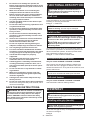
FUNCTIONAL DESCRIPTION
CAUTION: Always be sure that the tool is
switched o and unplugged before adjusting or
checking function on the tool.
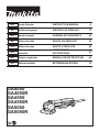
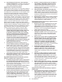
Shaft lock
Press the shaft lock to prevent spindle rotation when
installing or removing accessories.
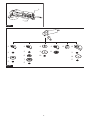
► Fig.1: 1. Shaft lock
NOTICE: Never actuate the shaft lock when the
spindle is moving. The tool may be damaged.
Switch action
CAUTION:
Before plugging in the tool, always
check to see that the switch trigger actuates properly
and returns to the "OFF" position when released.
CAUTION: Do not pull the switch lever forc-
ibly without pressing the lock-o button. The
switch may break.
To prevent the switch lever from accidentally pulled, a
lock-o lever is provided. To start the tool, pull the lock-
o lever toward the operator, and then pull the switch
lever. Release the switch lever to stop.
► Fig.2: 1. Lock-o lever 2. Switch lever
Unintentional restart proof
Only for model GA4050R / GA4550R / GA5050R
The tool does not start while pulling the switch lever
even when the tool is plugged. To start the tool, rst
release the switch lever. Then pull the lock-o lever, and
pull the switch lever.
NOTE: Wait more than one second before restarting
the tool when unintentional restart proof functions.
Soft start feature
Only for model GA4050R / GA4550R / GA5050R
Soft start feature reduces starting reaction.
ASSEMBLY
CAUTION: Always be sure that the tool is
switched o and unplugged before carrying out
any work on the tool.
Installing side grip (handle)
CAUTION: Always be sure that the side grip is
installed securely before operation.
Screw the side grip securely on the position of the tool
as shown in the gure.
► Fig.3

11 ENGLISH
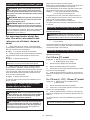
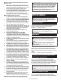
Installing or removing wheel guard
WARNING: When using a depressed center
wheel, ap disc, ex wheel or wire wheel brush,
the wheel guard must be tted on the tool so that
the closed side of the guard always points toward
the operator.
WARNING: Make sure that the wheel guard is
securely locked by the lock lever with one of the
holes on the wheel guard.
WARNING: When using an abrasive cut-o
/ diamond wheel, be sure to use only the special
wheel guard designed for use with cut-o wheels.
(In some European countries, when using a diamond
wheel, the ordinary guard can be used. Follow the
regulations in your country.)
For depressed center wheel, ap
disc, ex wheel, wire wheel brush
/ abrasive cut-o wheel, diamond
wheel
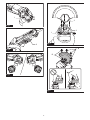
1. While pushing the lock lever, mount the wheel
guard with the protrusions on the wheel guard aligned
with the notches on the bearing box.
► Fig.4: 1. Lock lever 2. Notch 3. Protrusion
2. While pushing the lock lever toward A, hold down
the portions B of the wheel guard as shown in the
gure.
► Fig.5: 1. Wheel guard 2. Hole
NOTE: Push down the wheel guard straight.
Otherwise, you cannot secure the wheel guard.
3. While pushing the lock lever, rotate the wheel
guard toward C, and then, change the angle of the
wheel guard according to the work so that the operator
can be protected. Align the lock lever with one of the
holes in the wheel guard, and then release the lock
lever to lock the wheel guard.
► Fig.6: 1. Wheel guard 2. Hole
To remove wheel guard, follow the installation proce-
dure in reverse.
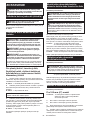
Installing or removing depressed
center wheel or ap disc
Optional accessory
WARNING: When using a depressed center
wheel or ap disc, the wheel guard must be tted
on the tool so that the closed side of the guard
always points toward the operator.
CAUTION: Make sure that the mounting part
of the inner ange ts into the inner diameter of
the depressed center wheel / ap disc perfectly.
Mounting the inner ange on the wrong side may
result in the dangerous vibration.
Mount the inner ange onto the spindle.
Make sure to t the dented part of the inner ange onto
the straight part at the bottom of the spindle.
Fit the depressed center wheel / ap disc on the inner
ange and screw the lock nut onto the spindle.
► Fig.7: 1. Lock nut 2. Depressed center wheel
3. Inner ange 4. Mounting part
To tighten the lock nut, press the shaft lock rmly so
that the spindle cannot revolve, then use the lock nut
wrench and securely tighten clockwise.
► Fig.8: 1. Lock nut wrench 2. Shaft lock
To remove the wheel, follow the installation procedure
in reverse.
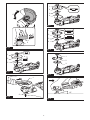
Installing or removing ex wheel
Optional accessory
WARNING: Always use supplied guard when
ex wheel is on tool. Wheel can shatter during use
and guard helps to reduce chances of personal injury.
► Fig.9: 1. Lock nut 2. Flex wheel 3. Back up pad
4. Inner ange
Follow instructions for depressed center wheel but also
use back up pad over wheel. See order of assembly on
accessories page in this manual.
Installing or removing abrasive disc
Optional accessory
For 100 mm (4″) model
► Fig.10: 1. Sanding lock nut 2. Abrasive disc
3. Rubber pad 4. Inner ange
1. Mount the inner ange onto the spindle.
2. Mount the rubber pad onto the spindle.
3. Fit the disc on the rubber pad and screw the sand-
ing lock nut onto the spindle.
4. Hold the spindle with the shaft lock, and securely
tighten the sanding lock nut clockwise with the lock nut
wrench.
For 115 mm (4 - 1/2″) / 125 mm (5″) model
► Fig.11: 1. Sanding lock nut 2. Abrasive disc
3. Rubber pad
1. Mount the rubber pad onto the spindle.
2. Fit the disc on the rubber pad and screw the sand-
ing lock nut onto the spindle.
3. Hold the spindle with the shaft lock, and securely
tighten the sanding lock nut clockwise with the lock nut
wrench.
To remove the disc, follow the installation procedure in
reverse.
NOTE: Use sander accessories specied in this man-
ual. These must be purchased separately.

12 ENGLISH
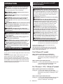
OPERATION
WARNING: It should never be necessary to
force the tool. The weight of the tool applies ade-
quate pressure. Forcing and excessive pressure
could cause dangerous wheel breakage.
WARNING: ALWAYS replace wheel if tool is
dropped while grinding.
WARNING: NEVER bang or hit grinding disc
or wheel onto work.
WARNING: Avoid bouncing and snagging
the wheel, especially when working corners,
sharp edges etc. This can cause loss of control and
kickback.
WARNING: NEVER use tool with wood cutting
blades and other saw blades. Such blades when
used on a grinder frequently kick and cause loss of
control leading to personal injury.
WARNING: Continued use of a worn-out
wheel may result in wheel explosion and serious
personal injury.
CAUTION: Never switch on the tool when it
is in contact with the workpiece, it may cause an
injury to operator.
CAUTION: Always wear safety goggles or a
face shield during operation.
CAUTION: After operation, always switch o
the tool and wait until the wheel has come to a
complete stop before putting the tool down.
CAUTION: ALWAYS hold the tool rmly with
one hand on housing and the other on the side
grip (handle).
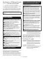
Operation with wheel/disc
► Fig.12
Turn the tool on and then apply the wheel or disc to the
workpiece.
In general, keep the edge of the wheel or disc at an
angle of about 15° to the workpiece surface.
During the break-in period with a new wheel, do not
work the grinder in forward direction or it may cut into
the workpiece. Once the edge of the wheel has been
rounded o by use, the wheel may be worked in both
forward and backward direction.
Operation with abrasive cut-o /
diamond wheel
Optional accessory
WARNING: When using an abrasive cut-o
/ diamond wheel, be sure to use only the special
wheel guard designed for use with cut-o wheels.
(In some European countries, when using a diamond
wheel, the ordinary guard can be used. Follow the
regulations in your country.)
WARNING:
NEVER use cut-o wheel for side grinding.
WARNING:
Do not "jam" the wheel or apply
excessive pressure. Do not attempt to make an exces-
sive depth of cut. Overstressing the wheel increases
the loading and susceptibility to twisting or binding of the
wheel in the cut and the possibility of kickback, wheel
breakage and overheating of the motor may occur.
WARNING:
Do not start the cutting operation
in the workpiece. Let the wheel reach full speed and
carefully enter into the cut moving the tool forward
over the workpiece surface. The wheel may bind, walk
up or kickback if the power tool is started in the workpiece.
WARNING:
During cutting operations, never
change the angle of the wheel. Placing side pressure
on the cut-o wheel (as in grinding) will cause the wheel
to crack and break, causing serious personal injury.
WARNING: A diamond wheel shall be oper-
ated perpendicular to the material being cut.
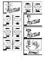
► Fig.13: 1. Lock nut 2. Abrasive cut-o wheel / dia-
mond wheel 3. Inner ange 4. Wheel guard
for abrasive cut-o wheel / diamond wheel
As for the installation, follow the instructions for
depressed center wheel.
The direction for mounting the lock nut and the
inner ange varies by wheel type and thickness.
Refer to the following gures.
For 100 mm (4″) model
When installing the abrasive cut-o wheel:
► Fig.14: 1. Lock nut 2. Abrasive cut-o wheel
(Thinner than 4 mm (5/32")) 3. Abrasive cut-
o wheel (4 mm (5/32") or thicker) 4. Inner
ange
When installing the diamond wheel:
► Fig.15: 1. Lock nut 2. Diamond wheel (Thinner than
4 mm (5/32″)) 3. Diamond wheel (4 mm
(5/32″) or thicker) 4. Inner ange
For 115 mm (4 - 1/2″) / 125 mm (5″) model
When installing the abrasive cut-o wheel:
► Fig.16: 1. Lock nut 2. Abrasive cut-o wheel
(Thinner than 4 mm (5/32")) 3. Abrasive cut-
o wheel (4 mm (5/32") or thicker) 4. Inner
ange
When installing the diamond wheel:
► Fig.17: 1. Lock nut 2. Diamond wheel (Thinner than
4 mm (5/32″)) 3. Diamond wheel (4 mm
(5/32″) or thicker) 4. Inner ange

13 ENGLISH
Operation with wire cup brush
Optional accessory
CAUTION: Check operation of brush by run-
ning tool with no load, insuring that no one is in
front of or in line with brush.
CAUTION: Do not use brush that is damaged,
or which is out of balance. Use of damaged brush
could increase potential for injury from contact with
broken brush wires.
► Fig.18: 1. Wire cup brush
Unplug tool and place it upside down allowing easy
access to spindle.
Remove any accessories on spindle. Thread wire cup
brush onto spindle and tighten with supplied wrench.
NOTICE: Avoid applying too much pressure
which causes over bending of wires when using
brush. It may lead to premature breakage.
Operation with wire wheel brush
Optional accessory
CAUTION: Check operation of wire wheel
brush by running tool with no load, insuring that
no one is in front of or in line with the wire wheel
brush.
CAUTION: Do not use wire wheel brush that
is damaged, or which is out of balance. Use of
damaged wire wheel brush could increase potential
for injury from contact with broken wires.
CAUTION: ALWAYS use guard with wire
wheel brushes, assuring diameter of wheel ts
inside guard. Wheel can shatter during use and
guard helps to reduce chances of personal injury.
► Fig.19: 1. Wire wheel brush
Unplug tool and place it upside down allowing easy
access to spindle.
Remove any accessories on spindle. Thread wire wheel
brush onto spindle and tighten with the wrenches.
NOTICE: Avoid applying too much pressure
which causes over bending of wires when
using wire wheel brush. It may lead to premature
breakage.
Lanyard (tether strap) connection
Safety warnings specic for use at height
Read all safety warnings and instructions. Failure to follow
the warnings and instructions may result in serious injury.
1. Always keep the tool tethered when working
"at height". Maximum lanyard length is 2 m.
The maximum permissible fall height for lan-
yard (tether strap) must not exceed 2 m.
2. Use only with lanyards appropriate for this tool
type and rated for at least 4.0 kg.
3. Do not anchor the tool lanyard to anything on
your body or on movable components. Anchor
the tool lanyard to a rigid structure that can
withstand the forces of a dropped tool.
4. Make sure the lanyard is properly secured at
each end prior to use.
5. Inspect the tool and lanyard before each use
for damage and proper function (including
fabric and stitching). Do not use if damaged
or not functioning properly. The tool must be
repaired especially when a crack or a red line
appears around the hole for the lanyard.
6. Do not wrap lanyards around or allow them to
come in contact with sharp or rough edges.
7.
Fasten the other end of the lanyard outside the
working area so that a falling tool is held securely.
8. Attach the lanyard so that the tool will move
away from the operator if it falls. Dropped tools
will swing on the lanyard, which could cause injury
or loss of balance.
9. Do not use near moving parts or running
machinery. Failure to do so may result in a crush
or entanglement hazard.
10. Do not carry the tool by the attachment device
or the lanyard.
11. Only transfer the tool between your hands
while you are properly balanced.
12. Do not attach lanyards to the tool in a way that
keeps guards, switches or lock-os from oper-
ating properly.
13. Avoid getting tangled in the lanyard.
14.
Keep lanyard away from the cutting area of the tool.
15. Use a locking carabiner (multi-action and
screw gate type). Do not use single action
spring clip carabiners.
16. In the event the tool is dropped, it must be
tagged and removed from service, and should
be inspected by a Makita Factory or Authorized
Service Center.
17. Only attach the lanyard with a locking cara-
biner. Do not attach the lanyard by looping
or knotting the lanyard. Do not use ropes or
cords.
► Fig.20: 1. Hole for lanyard (tether strap)
MAINTENANCE
CAUTION: Always be sure that the tool is
switched o and unplugged before attempting to
perform inspection or maintenance.
NOTICE: Never use gasoline, benzine, thinner,
alcohol or the like. Discoloration, deformation or
cracks may result.
To maintain product SAFETY and RELIABILITY,
repairs, any other maintenance or adjustment should
be performed by Makita Authorized or Factory Service
Centers, always using Makita replacement parts.
Air vent cleaning
The tool and its air vents have to be kept clean.
Regularly clean the tool's air vents or whenever the
vents start to become obstructed.
► Fig.21: 1. Exhaust vent 2. Inhalation vent

14 ENGLISH
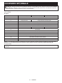
OPTIONAL ACCESSORIES
CAUTION: These accessories or attachments are recommended for use with your Makita tool spec-
ied in this manual. The use of any other accessories or attachments might present a risk of injury to persons.
Only use accessory or attachment for its stated purpose.
If you need any assistance for more details regarding these accessories, ask your local Makita Service Center.
► Fig.22
-100 mm (4″) model 115 mm (4-1/2″) model 125 mm (5″) model
1Side grip
2Wheel Guard (for grinding wheel)
3Inner ange Inner ange / Super ange
4Depressed center wheel / Flap disc
5Lock nut
6Back up pad
7Flex wheel
8Rubber pad 76 Rubber pad 100 Rubber pad 115
9Abrasive disc
10 Sanding lock nut
11 Wire wheel brush
12 Wire cup brush
13 Wheel Guard (for cut-o wheel) *1
14 Abrasive cut-o wheel / Diamond wheel
-Lock nut wrench
-Dust cover attachment
NOTE: *1 In some European countries, when using a diamond wheel, the ordinary guard can be used instead of the
special guard covering the both side of the wheel. Follow the regulations in your country.
NOTE: Some items in the list may be included in the tool package as standard accessories. They may dier from
country to country.

15 POLSKI
POLSKI (Instrukcja oryginalna)
DANE TECHNICZNE
Model: GA4050
GA4050R
GA4550
GA4550R
GA5050
GA5050R
Średnica ściernicy 100 mm (4″) 115 mm (4-1/2″) 125 mm (5″)
Maks. grubość ściernicy 6,4 mm (1/4″) 7,2 mm (9/32″)
Gwint wrzeciona M10 M14 lub 5/8″
Prędkość znamionowa (n) 11 000 min-1
Długość całkowita 325 mm
Ciężar netto 2,3–2,6 kg
2,4–2,8 kg
2,5–2,8 kg
Klasa bezpieczeństwa /II
• W związku ze stale prowadzonym przez naszą rmę programem badawczo-rozwojowym niniejsze dane mogą
ulec zmianom bez wcześniejszego powiadomienia.
• Dane techniczne mogą różnić się w zależności od kraju.
• Wysokość może być różna w zależności od osprzętu. W tabeli została przedstawiona najlżejsza i najcięższa
konguracja zgodnie z procedurą EPTA 01/2014.
Przeznaczenie
Omawiane narzędzie jest przeznaczone do szlifowania i
cięcia materiałów metalowych i kamiennych bez użycia
wody.
Zasilanie
Narzędzie wolno podłączać tylko do źródeł zasilania o
napięciu zgodnym z napięciem podanym na tabliczce
znamionowej. Można je zasilać wyłącznie jednofazo-
wym prądem przemiennym. Narzędzie ma podwójną
izolację, dlatego też można je zasilać z gniazda elek-
trycznego bez uziemienia.
Hałas
Typowy równoważny poziom dźwięku A określony w oparciu o normę EN60745-2-3:
Model Poziom ciśnienia
akustycznego (LpA):
(dB(A))
Poziom mocy
akustycznej (LWA):
(dB(A))
Niepewność (K):
(dB(A))
GA4050 91 102 3
GA4050R 91 102 3
GA4550 91 102 3
GA4550R 91 102 3
GA5050 91 102 3
GA5050R 91 102 3
WSKAZÓWKA: Deklarowana wartość emisji hałasu została zmierzona zgodnie ze standardową metodą testową i
można ją wykorzystać do porównywania narzędzi.
WSKAZÓWKA: Deklarowaną wartość emisji hałasu można także wykorzystać we wstępnej ocenie narażenia.
OSTRZEŻENIE: Nosić ochronniki słuchu.
OSTRZEŻENIE: Poziom hałasu wytwarzanego podczas rzeczywistego użytkowania elektronarzędzia
może się różnić od wartości deklarowanej w zależności od sposobu użytkowania narzędzia, a w szczegól-
ności od rodzaju obrabianego elementu.
OSTRZEŻENIE: W oparciu o szacowane narażenie w rzeczywistych warunkach użytkowania należy
określić środki bezpieczeństwa w celu zapewnienia ochrony operatora (uwzględniając wszystkie elementy
cyklu działania, tj. czas, kiedy narzędzie jest wyłączone i kiedy pracuje na biegu jałowym, a także czas,
kiedy jest włączone).

16 POLSKI
Drgania
Całkowita wartość poziomu drgań (suma wektorów w 3 osiach) określona zgodnie z normą EN60745-2-3:
Tryb pracy: szlifowanie powierzchni ze standardowym uchwytem bocznym
Model Emisja drgań (ah, AG): (m/s2)Niepewność (K): (m/s2)
GA4050 6,5 1,5
GA4050R 6,5 1,5
GA4550 7,0 1,5
GA4550R 7,0 1,5
GA5050 7,5 1,5
GA5050R 7,5 1,5
Tryb pracy: szlifowanie powierzchni z antywibracyjnym uchwytem bocznym
Model Emisja drgań (ah, AG): (m/s2)Niepewność (K): (m/s2)
GA4050 5,5 1,5
GA4050R 5,5 1,5
GA4550 7,0 1,5
GA4550R 7,0 1,5
GA5050 8,5 1,5
GA5050R 8,5 1,5
Tryb pracy: szlifowanie krążkami ściernymi ze standardowym uchwytem bocznym
Model Emisja drgań (ah, AG): (m/s2)Niepewność (K): (m/s2)
GA4050 2,5 m/s2 lub mniej 1,5
GA4050R 2,5 m/s2 lub mniej 1,5
GA4550 2,5 1,5
GA4550R 2,5 1,5
GA5050 2,5 m/s2 lub mniej 1,5
GA5050R 2,5 m/s2 lub mniej 1,5
Tryb pracy: szlifowanie krążkami ściernymi z antywibracyjnym uchwytem bocznym
Model Emisja drgań (ah, AG): (m/s2)Niepewność (K): (m/s2)
GA4050 2,5 m/s2 lub mniej 1,5
GA4050R 2,5 m/s2 lub mniej 1,5
GA4550 2,5 m/s2 lub mniej 1,5
GA4550R 2,5 m/s2 lub mniej 1,5
GA5050 2,5 m/s2 lub mniej 1,5
GA5050R 2,5 m/s2 lub mniej 1,5
WSKAZÓWKA: Deklarowana wartość poziomu drgań została zmierzona zgodnie ze standardową metodą
testową i można ją wykorzystać do porównywania narzędzi.
WSKAZÓWKA: Deklarowaną wartość poziomu drgań można także wykorzystać we wstępnej ocenie narażenia.
OSTRZEŻENIE: Drgania wytwarzane podczas rzeczywistego użytkowania elektronarzędzia mogą się
różnić od wartości deklarowanej w zależności od sposobu użytkowania narzędzia, a w szczególności od
rodzaju obrabianego elementu.
OSTRZEŻENIE: W oparciu o szacowane narażenie w rzeczywistych warunkach użytkowania należy
określić środki bezpieczeństwa w celu zapewnienia ochrony operatora (uwzględniając wszystkie elementy
cyklu działania, tj. czas, kiedy narzędzie jest wyłączone i kiedy pracuje na biegu jałowym, a także czas,
kiedy jest włączone).
OSTRZEŻENIE: Deklarowaną wartość emisji drgań stosuje się do głównych zastosowań elektronarzędzia.
Jeśli jednak elektronarzędzie będzie wykorzystywane do innych zastosowań, wartość emisji drgań może być inna.

17 POLSKI
Deklaracja zgodności WE
Dotyczy tylko krajów europejskich
Deklaracja zgodności WE jest dołączona jako załącznik
A do niniejszej instrukcji obsługi.
OSTRZEŻENIA DOTYCZĄCE
BEZPIECZEŃSTWA
Ogólne zasady bezpiecznej
eksploatacji elektronarzędzi
OSTRZEŻENIE: Należy zapoznać się z
ostrzeżeniami dotyczącymi bezpieczeństwa,
instrukcjami, ilustracjami i danymi technicz-
nymi dołączonymi do tego elektronarzędzia.
Niezastosowanie się do podanych poniżej instrukcji
może prowadzić do porażenia prądem, pożaru i/lub
poważnych obrażeń ciała.
Wszystkie ostrzeżenia i instruk-
cje należy zachować do wykorzy-
stania w przyszłości.
Pojęcie „elektronarzędzie", występujące w wymienio-
nych tu ostrzeżeniach, odnosi się do elektronarzędzia
zasilanego z sieci elektrycznej (z przewodem zasilają-
cym) lub do elektronarzędzia akumulatorowego (bez
przewodu zasilającego).
Ostrzeżenia dotyczące
bezpieczeństwa dla szlierki
Ostrzeżenia dotyczące bezpieczeństwa podczas
operacji szlifowania, czyszczenia powierzchni
szczotką drucianą lub cięcia przy użyciu ściernicy:
1. Opisywane elektronarzędzie jest przeznaczone
do szlifowania, czyszczenia powierzchni
szczotką drucianą i cięcia. Należy zapoznać się
z ostrzeżeniami dotyczącymi bezpieczeństwa,
instrukcjami, ilustracjami i danymi technicz-
nymi dołączonymi do tego elektronarzędzia.
Niezastosowanie się do podanych poniżej instruk-
cji może prowadzić do porażenia prądem elek-
trycznym, pożaru i/lub poważnych obrażeń ciała.
2. Nie zaleca się używania niniejszego elektro-
narzędzia do wykonywania takich operacji jak
polerowanie. Operacje, do których elektronarzę-
dzie nie jest przeznaczone, mogą stwarzać zagro-
żenie i spowodować obrażenia ciała.
3. Nie używać osprzętu, który nie jest przezna-
czony ani zalecany specjalnie do tego narzę-
dzia przez jego producenta. Fakt, że osprzęt
można zamocować do posiadanego elektronarzę-
dzia, wcale nie gwarantuje bezpiecznej pracy.
4. Prędkość znamionowa osprzętu powinna być
przynajmniej równa maksymalnej prędkości
podanej na elektronarzędziu. Osprzęt pracujący
przy większej prędkości niż jego prędkość zna-
mionowa może pęknąć i rozpaść się na kawałki.
5.
Zewnętrzna średnica i grubość osprzętu musi
mieścić się w zakresie dopuszczalnym dla tego
elektronarzędzia. Nie można zapewnić prawidłowej
osłony i kontroli osprzętu o niewłaściwym rozmiarze.
6.
Osprzęt montowany na gwint musi pasować do
gwintu wrzeciona szlierki. W przypadku osprzętu
montowanego przy użyciu kołnierzy otwór
wewnętrzny osprzętu musi pasować do średnicy
kołnierza. Osprzęt, który nie jest dopasowany do
uchwytu mocującego w elektronarzędziu będzie
niewyważony podczas pracy, powodując nadmierne
drgania i ryzyko utraty kontroli nad narzędziem.
7.
Nie używać uszkodzonego osprzętu. Przed
każdorazowym użyciem osprzęt, np. ściernice,
należy skontrolować pod kątem ubytków lub
pęknięć, tarcze oporowe należy skontrolować
pod kątem pęknięć, uszkodzeń lub nadmier-
nego zużycia, a szczotki druciane pod kątem
luźnych lub popękanych drutów. W przypadku
upuszczenia elektronarzędzia lub osprzętu
należy sprawdzić, czy nie doszło do uszkodze-
nia, lub zamontować nieuszkodzony osprzęt.
Po sprawdzeniu bądź zamontowaniu osprzętu
należy stanąć w taki sposób i tak ustawić narzę-
dzie, aby nikt nie znajdował się w płaszczyźnie
obrotu osprzętu, po czym na jedną minutę
uruchomić elektronarzędzie z maksymalną
prędkością bez obciążenia. Uszkodzony osprzęt
zazwyczaj rozpadnie się podczas takiej próby.
8.
Używać środków ochrony osobistej. W zależ-
ności od wykonywanej operacji należy używać
osłony twarzy, gogli lub okularów ochronnych.
W miarę potrzeb zakładać maskę przeciwpyłową,
ochronniki słuchu, rękawice i fartuch, który
zatrzyma drobiny materiału ściernego i obrabia-
nego przedmiotu. Środki ochrony oczu powinny
zatrzymywać unoszące się w powietrzu drobiny
materiału, które powstają podczas różnych operacji.
Maska przeciwpyłowa lub oddechowa powinna
ltrować cząsteczki, które powstają podczas pracy.
Przebywanie przez dłuższy czas w hałasie o dużym
natężeniu może spowodować utratę słuchu.
9.
Trzymać osoby postronne w bezpiecznej odle-
głości od miejsca pracy. Każdy, kto wchodzi
do obszaru roboczego, musi używać środków
ochrony osobistej. Fragmenty materiału z obra-
bianego elementu lub pękniętego osprzętu mogą
zostać odrzucone na dużą odległość i spowodować
obrażenia poza bezpośrednim obszarem roboczym.
10. Trzymać elektronarzędzie za izolowane
powierzchnie rękojeści podczas wykonywania
prac, przy których osprzęt tnący może dotknąć
niewidocznej instalacji elektrycznej. Zetknięcie
osprzętu tnącego z przewodem elektrycznym
znajdującym się pod napięciem może spowodo-
wać, że odsłonięte elementy metalowe elektrona-
rzędzia również znajdą się pod napięciem, grożąc
porażeniem operatora prądem elektrycznym.
11.
Przewód należy trzymać w bezpiecznej odległo-
ści od wirującego osprzętu. W przypadku utraty
kontroli przewód może zostać przecięty lub wkrę-
cony, wciągając dłoń lub rękę w wirujący osprzęt.
12. Nie wolno odkładać elektronarzędzia, dopóki
zamontowany osprzęt całkowicie się nie
zatrzyma. Wirujący osprzęt może zahaczyć o
powierzchnię i wyrwać elektronarzędzie z ręki.

18 POLSKI
13. Uruchomionego elektronarzędzia nie wolno
przenosić z miejsca na miejsce. Przypadkowy
kontakt z wirującym osprzętem może spowodo-
wać zahaczenie ubrania i obrażenia ciała.
14. Otwory wentylacyjne elektronarzędzia należy
regularnie czyścić. Wentylator silnika wciąga
do wnętrza obudowy pył. Zbyt duże nagroma-
dzenie metalowych drobin stwarza zagrożenia
elektryczne.
15. Nie używać elektronarzędzia w pobliżu mate-
riałów łatwopalnych. Iskry mogą spowodować
zapłon takich materiałów.
16. Nie używać osprzętu, który wymaga stosowa-
nia ciekłego chłodziwa. Użycie wody lub innych
ciekłych chłodziw może spowodować porażenie
prądem elektrycznym, także śmiertelne.
Odrzut i związane z nim ostrzeżenia
Odrzut to gwałtowna reakcja narzędzia na zakleszcze-
nie lub zahaczenie obracającej się ściernicy, tarczy opo-
rowej, szczotki drucianej lub innego rodzaju osprzętu.
Zakleszczenie lub zahaczenie powoduje nagłe zatrzy-
manie obracającego się osprzętu, co z kolei prowadzi
do niekontrolowanego odrzutu elektronarzędzia do
kierunku obrotu osprzętu w miejscu zakleszczenia.
Przykładowo, jeśli ściernica zahaczy się lub zakleszczy
w obrabianym elemencie, jej krawędź w punkcie zaklesz-
czenia może wbić się powierzchnie materiału, powodując
wypychanie i odskoczenie narzędzia na zewnątrz ele-
mentu. Ściernica może odskoczyć w stronę operatora lub
w kierunku przeciwnym, w zależności od kierunku obro-
tów ściernicy w punkcie zakleszczenia. W takich warun-
kach może również dojść do pęknięcia ściernicy.
Odrzut jest wynikiem nieprawidłowego używania elek-
tronarzędzia i/lub niewłaściwych procedur lub warun-
ków jego obsługi. Można tego uniknąć, podejmując
odpowiednie środki ostrożności, które podano poniżej.
1. Przez cały czas należy mocno trzymać elektro-
narzędzie, ustawiając ciało i ramię w taki spo-
sób, aby przeciwdziałać siłom odrzutu. Zawsze
należy korzystać z rękojeści pomocniczej,
jeśli jest w zestawie, aby móc w pełni kontro-
lować odrzut lub przeciwdziałać momentowi
obrotowemu podczas rozruchu. Operator może
kontrolować reakcje na moment obrotowy lub siły
odrzutu w przypadku stosowania odpowiednich
środków ostrożności.
2. Nie wolno trzymać rąk w pobliżu obracającego
się osprzętu. Może bowiem nastąpić odrzut w
kierunku ręki.
3. Ciało operatora nie powinno znajdować się w
obszarze, do którego przemieści się elektro-
narzędzie w przypadku wystąpienia odrzutu.
Odrzut spowoduje wyrzucenie narzędzia w kie-
runku przeciwnym do kierunku obrotów ściernicy
w miejscu zakleszczenia.
4. Zachować szczególną ostrożność podczas
obróbki narożników, ostrych krawędzi itp. Nie
dopuszczać do odskakiwania i zahaczania się
osprzętu. Narożniki, ostre krawędzie lub odska-
kiwanie sprzyjają zahaczaniu obracającego się
osprzętu i mogą spowodować utratę kontroli lub
odrzut.
5. Nie wolno montować do elektronarzędzia tarcz
łańcuchowych do cięcia drewna ani zębatych
tarcz tnących. Tego typu tarcze często powodują
odrzut i utratę kontroli.
Ostrzeżenia dotyczące bezpieczeństwa podczas
operacji szlifowania i cięcia przy użyciu ściernicy:
1.
Używać wyłącznie ściernic zalecanych do
posiadanego elektronarzędzia oraz specjalnych
osłon przeznaczonych do wybranego rodzaju
ściernicy. Nie można zapewnić prawidłowej osłony
ściernic, do których elektronarzędzie nie jest prze-
znaczone. Takie ściernice są niebezpieczne.
2. Powierzchnia szlifowania ściernic z obniżo-
nym środkiem musi być zamontowana poniżej
płaszczyzny krawędzi osłony. Nieprawidłowo
zamontowana ściernica, która wystaje poza płasz-
czyznę krawędzi osłony, nie może być odpowied-
nio zabezpieczona.
3. Osłona powinna być dobrze przymocowana do
elektronarzędzia i ustawiona w sposób zapew-
niający maksimum bezpieczeństwa, tak aby w
stronę operatora był skierowany jak najmniej-
szy fragment odsłoniętej ściernicy. Osłona
chroni operatora przed wykruszonymi odłamkami
ściernicy, przypadkowym kontaktem ze ściernicą
oraz przed iskrami, które mogłyby zapalić odzież.
4. Ściernic należy używać tylko zgodnie z prze-
znaczeniem. Na przykład: nie wolno szlifo-
wać boczną powierzchnią ściernicy tnącej.
Ściernice tnące są przeznaczone do szlifowania
obwodowego. Siły boczne przyłożone do takich
ściernic mogą spowodować ich rozpadnięcie.
5.
Zawsze używać nieuszkodzonych kołnierzy
mocujących o rozmiarze i kształcie właściwie
dobranym do wybranego rodzaju ściernicy.
Odpowiednie kołnierze mocujące podtrzymują ścier-
nicę, zmniejszając tym samym prawdopodobieństwo
jej pęknięcia. Kołnierze do ściernic tnących mogą
różnić się od kołnierzy do ściernic szlierskich.
6.
Nie używać zużytych ściernic przeznaczonych
do większych elektronarzędzi. Ściernica przezna-
czona do większych elektronarzędzi nie nadaje się
do użytku przy wyższych prędkościach występują-
cych w mniejszych narzędziach i może się rozpaść.
Dodatkowe ostrzeżenia dotyczące bezpieczeństwa
podczas operacji cięcia przy użyciu ściernicy:
1. Nie wolno doprowadzać do zakleszczenia
ściernicy tnącej ani stosować zbyt dużego
nacisku. Unikać cięć o zbyt dużej głębokości.
Przeciążona ściernica jest bardziej podatna na
skręcenie lub zakleszczenie w miejscu cięcia, co
stwarza większe prawdopodobieństwo odrzutu lub
pęknięcia ściernicy.
2. Ciało operatora nie powinno znajdować się
w płaszczyźnie obrotu ściernicy ani za obra-
cającą się ściernicą. Gdy ściernica odsuwa się
podczas pracy od operatora, ewentualny odrzut
może wypchnąć wirującą ściernicę i elektronarzę-
dzie bezpośrednio w kierunku operatora.
3. W przypadku zakleszczenia się ściernicy lub
przerwania cięcia z jakiegokolwiek powodu,
należy wyłączyć elektronarzędzie i trzymać
je w bezruchu do momentu całkowitego
zatrzymania się ściernicy. Nie wolno wyciągać
ściernicy tnącej z przecinanego elementu, gdy
ściernica znajduje się w ruchu; w przeciwnym
razie może wystąpić odrzut. Zbadać przyczynę
zakleszczania się ściernicy i podjąć stosowne
działanie, aby wyeliminować ten problem.

19 POLSKI
4. Nie wolno wznawiać cięcia, gdy ściernica znaj-
duje się w przecinanym elemencie. Ściernicę
można ponownie włożyć do naciętej szczeliny
dopiero, gdy osiągnie pełną prędkość. Jeśli
elektronarzędzie zostanie ponownie uruchomione,
gdy ściernica znajduje się w przecinanym elemen-
cie, ściernica może się zakleszczyć, wędrować po
materiale lub może wystąpić odrzut.
5. Duże elementy lub płyty należy podpierać, aby
zminimalizować ryzyko zakleszczenia ścier-
nicy i wystąpienia odrzutu. Duże elementy mają
tendencję do uginania się pod własnym ciężarem.
Podpory muszą być umieszczone pod przeci-
nanym elementem w pobliżu linii cięcia oraz w
pobliżu krawędzi przecinanego elementu, po obu
stronach ściernicy.
6. Należy zachować szczególną ostrożność w
przypadku wykonywania „cięć wgłębnych”
w istniejących ścianach bądź innych zakry-
tych przestrzeniach. Wystająca ściernica może
przeciąć rury sieci gazowej lub wodociągowej,
przewody elektryczne lub przedmioty, które z kolei
mogą wywołać odrzut.
Specjalne ostrzeżenia dotyczące bezpieczeństwa
podczas operacji szlifowania:
1. Nie należy używać krążków papieru ściernego
o zbyt dużej średnicy. Przy doborze papieru
ściernego należy kierować się zaleceniami
producenta. Papier ścierny o zbyt dużych wymia-
rach, wystający poza obręb talerza szlierskiego,
grozi zranieniem i może powodować zaczepianie,
rozrywanie krążka lub odrzut.
Specjalne ostrzeżenia dotyczące bezpieczeństwa
podczas operacji czyszczenia powierzchni szczotką
drucianą:
1. Należy mieć świadomość, że nawet podczas
zwykłej pracy ze szczotki są wyrzucane
kawałki drutów. Nie wolno nadmiernie naprę-
żać drutów przez wywieranie zbyt dużego
nacisku na szczotkę. Druty ze szczotki mogą z
łatwością przebić lekkie ubranie i/lub skórę.
2. Jeśli podczas operacji czyszczenia
powierzchni szczotką drucianą wskazane jest
używanie osłony, należy uważać, aby szczotka
tarczowa ani druciana nie ocierały o osłonę.
Średnica szczotki tarczowej lub drucianej może
podczas pracy ulegać zwiększeniu pod wpływem
obciążenia roboczego i sił odśrodkowych.
Dodatkowe ostrzeżenia dotyczące bezpieczeństwa:
1. W przypadku używania ściernic z obniżonym
środkiem należy używać wyłącznie ściernic
wzmocnionych włóknem szklanym.
2. NIE WOLNO używać w tej szlierce ściernic
garnkowych. Niniejsza szlierka nie jest prze-
widziana do tego rodzaju ściernic i ich używanie
może spowodować poważne obrażenia ciała.
3. Uważać, aby nie uszkodzić wrzeciona, kołnie-
rza (zwłaszcza powierzchni odpowiedzialnych
za prawidłowy montaż) ani nakrętki zabezpie-
czającej. Uszkodzenie tych części może stać
się przyczyną pęknięcia ściernicy.
4. Przed włączeniem przełącznika należy się
upewnić, że ściernica nie dotyka obrabianego
elementu.
5. Przed rozpoczęciem obróbki danego elementu
pozwolić, aby urządzenie popracowało przez
chwilę bez obciążenia. Zwracać uwagę na
ewentualne drgania lub bicie osiowe, które
mogą wskazywać na nieprawidłowe zamoco-
wanie lub niedokładne wyważenie ściernicy.
6. Podczas szlifowania używać określonej
powierzchni ściernicy.
7. Nie pozostawiać włączonego narzędzia.
Narzędzie można uruchomić tylko, gdy jest
trzymane w rękach.
8. Nie dotykać elementu obrabianego od razu
po zakończeniu danej operacji; może być on
bardzo gorący i spowodować oparzenie skóry.
9. Nie dotykać akcesoriów od razu po zakoń-
czeniu danej operacji; mogą być one bardzo
gorące i spowodować oparzenie skóry.
10.
Przestrzegać instrukcji producenta w zakresie
mocowania i użytkowania ściernic. Ściernice
przechowywać i obchodzić się z nimi z dbałością.
11. Nie wolno używać oddzielnych tulei reduk-
cyjnych ani elementów pośrednich w celu
zamocowania ściernic o dużym otworze
wewnętrznym.
12. Używać wyłącznie kołnierzy przeznaczonych
do tego narzędzia.
13. W przypadku narzędzi współpracujących ze
ściernicami z nagwintowanym otworem należy
sprawdzić, czy długość gwintu w ściernicy jest
wystarczająca, aby wkręcić wrzeciono na całej
długości.
14. Sprawdzić, czy obrabiany element jest dobrze
podparty.
15. Należy pamiętać, że po wyłączeniu narzędzia
ściernica nadal się obraca.
16. Jeśli w miejscu pracy panuje wyjątkowo
wysoka temperatura i wilgotność albo wystę-
puje silnie zanieczyszczone przewodzącym
pyłem, należy zastosować wyłącznik (30 mA),
aby zapewnić operatorowi bezpieczeństwo.
17. Nie wolno używać tego narzędzia do obróbki
materiałów zawierających azbest.
18.
W przypadku używania ściernicy tnącej należy
zawsze stosować osłonę do odsysania pyłu
wymaganą przez obowiązujące przepisy krajowe.
19. Na ściernice tnące nie wolno wywierać nacisku
poprzecznego.
20. Podczas pracy nie należy używać materia-
łowych rękawic roboczych. Włókna z rękawic
materiałowych mogą zostać pochwycone przez
narzędzie, co może spowodować uszkodzenie
narzędzia.
ZACHOWAĆ NINIEJSZĄ
INSTRUKCJĘ.
OSTRZEŻENIE: NIE WOLNO pozwolić,
aby wygoda lub rutyna (nabyta w wyniku wielo-
krotnego używania urządzenia) zastąpiły ścisłe
przestrzeganie zasad bezpieczeństwa obsługi.
NIEWŁAŚCIWE UŻYTKOWANIE narzędzia lub
niestosowanie się do zasad bezpieczeństwa
podanych w niniejszej instrukcji obsługi może
prowadzić do poważnych obrażeń ciała.

20 POLSKI
OPIS DZIAŁANIA
PRZESTROGA: Przed rozpoczęciem regulacji
lub sprawdzeniem działania narzędzia należy
upewnić się, że jest ono wyłączone i nie podłą-
czone do sieci.
Blokada wałka
Przed przystąpieniem do zakładania bądź zdejmowania
osprzętu należy nacisnąć blokadę wałka, aby unieru-
chomić wrzeciono.
► Rys.1: 1. Blokada wałka
UWAGA: Nie wolno włączać blokady wałka, gdy
wrzeciono jest w ruchu. Narzędzie może ulec
uszkodzeniu.
Działanie przełącznika
PRZESTROGA: Przed podłączeniem narzędzia
do zasilania należy zawsze sprawdzić, czy spust
przełącznika działa prawidłowo oraz czy wraca do
położenia wyłączenia po zwolnieniu.
PRZESTROGA: Nie należy ciągnąć na siłę
dźwigni przełącznika bez uprzedniego wciśnięcia
przycisku blokady włączenia. Przełącznik może
ulec uszkodzeniu.
Aby nie dopuścić do przypadkowego pociągnięcia
dźwigni przełącznika, narzędzie jest wyposażone w
dźwignię blokady włączenia. Aby uruchomić narzędzie,
należy pociągnąć dźwignię blokady włączenia w kie-
runku operatora, a następnie pociągnąć dźwignię prze-
łącznika. Aby zatrzymać urządzenie, wystarczy zwolnić
dźwignię przełącznika.
► Rys.2: 1. Dźwignia blokady włączenia 2. Dźwignia
przełącznika
Zabezpieczenie przed
przypadkowym włączeniem
Dotyczy tylko modeli GA4050R / GA4550R /
GA5050R
Pociągnięcie dźwigni przełącznika nie spowoduje uru-
chomienia narzędzia, nawet gdy jest ono podłączone
do zasilania. W celu uruchomienia narzędzia należy
najpierw zwolnić dźwignię przełącznika. Następnie
należy pociągnąć dźwignię blokady włączenia i dźwi-
gnię przełącznika.
WSKAZÓWKA: W przypadku działania zabezpiecze-
nia przed przypadkowym włączeniem przed ponow-
nym uruchomieniem narzędzia należy poczekać co
najmniej jedną sekundę.
Funkcja łagodnego rozruchu
Dotyczy tylko modeli GA4050R / GA4550R /
GA5050R
Funkcja łagodnego rozruchu niweluje występowanie
wstrząsu przy rozruchu.
MONTAŻ
PRZESTROGA: Przed wykonywaniem jakich-
kolwiek prac przy narzędziu należy upewnić się,
że jest ono wyłączone i odłączone od zasilania.
Zakładanie uchwytu bocznego
(rękojeści)
PRZESTROGA: Przed uruchomieniem należy
zawsze sprawdzić, czy uchwyt boczny jest dobrze
zamontowany.
Uchwyt boczny należy dobrze przykręcić w odpowied-
nim miejscu narzędzia, jak pokazano na rysunku.
► Rys.3
Zakładanie lub zdejmowanie osłony
ściernicy
OSTRZEŻENIE: W przypadku używania ścier-
nicy z obniżonym środkiem, ściernicy lamelko-
wej, ściernicy elastycznej lub drucianej szczotki
tarczowej osłonę ściernicy należy zamontować na
narzędziu w taki sposób, aby jej zamknięta część
była zawsze zwrócona w stronę operatora.
OSTRZEŻENIE: Upewnić się, że osłona ścier-
nicy jest skutecznie zablokowana przez dźwignię
blokady w jednym z otworów w osłonie ściernicy.
OSTRZEŻENIE: W przypadku używania
ściernicy tnącej / tarczy diamentowej należy uży-
wać wyłącznie specjalnej osłony przeznaczonej
do tego typu ściernic.
(W niektórych krajach europejskich w przypadku sto-
sowania tarczy diamentowej można używać zwykłej
osłony. Należy przestrzegać przepisów obowiązują-
cych w danym kraju).
Dotyczy ściernicy z obniżonym
środkiem, ściernicy lamelkowej,
ściernicy elastycznej, drucianej
szczotki tarczowej / ściernicy tnącej,
tarczy diamentowej
1. Naciskając dźwignię blokady, zamontować osłonę
ściernicy, tak aby występy na osłonie ściernicy pokry-
wały się z wycięciami w obudowie łożyska.
► Rys.4: 1. Dźwignia blokady 2. Wycięcie 3. Występ
2. Popychając dźwignię blokady w kierunku A,
należy przytrzymywać części B osłony ściernicy w
sposób pokazany na rysunku.
► Rys.5: 1. Osłona ściernicy 2. Otwór
WSKAZÓWKA: Popchnąć osłonę ściernicy prosto w
dół. W przeciwnym razie całkowite dociśnięcie osłony
ściernicy będzie niemożliwe.
Pagina se încarcă...
Pagina se încarcă...
Pagina se încarcă...
Pagina se încarcă...
Pagina se încarcă...
Pagina se încarcă...
Pagina se încarcă...
Pagina se încarcă...
Pagina se încarcă...
Pagina se încarcă...
Pagina se încarcă...
Pagina se încarcă...
Pagina se încarcă...
Pagina se încarcă...
Pagina se încarcă...
Pagina se încarcă...
Pagina se încarcă...
Pagina se încarcă...
Pagina se încarcă...
Pagina se încarcă...
Pagina se încarcă...
Pagina se încarcă...
Pagina se încarcă...
Pagina se încarcă...
Pagina se încarcă...
Pagina se încarcă...
Pagina se încarcă...
Pagina se încarcă...
Pagina se încarcă...
Pagina se încarcă...
Pagina se încarcă...
Pagina se încarcă...
Pagina se încarcă...
Pagina se încarcă...
Pagina se încarcă...
Pagina se încarcă...
Pagina se încarcă...
Pagina se încarcă...
Pagina se încarcă...
Pagina se încarcă...
Pagina se încarcă...
Pagina se încarcă...
Pagina se încarcă...
Pagina se încarcă...
Pagina se încarcă...
Pagina se încarcă...
Pagina se încarcă...
Pagina se încarcă...
Pagina se încarcă...
Pagina se încarcă...
Pagina se încarcă...
Pagina se încarcă...
Pagina se încarcă...
Pagina se încarcă...
Pagina se încarcă...
Pagina se încarcă...
Pagina se încarcă...
Pagina se încarcă...
Pagina se încarcă...
Pagina se încarcă...
Pagina se încarcă...
Pagina se încarcă...
Pagina se încarcă...
Pagina se încarcă...
-
 1
1
-
 2
2
-
 3
3
-
 4
4
-
 5
5
-
 6
6
-
 7
7
-
 8
8
-
 9
9
-
 10
10
-
 11
11
-
 12
12
-
 13
13
-
 14
14
-
 15
15
-
 16
16
-
 17
17
-
 18
18
-
 19
19
-
 20
20
-
 21
21
-
 22
22
-
 23
23
-
 24
24
-
 25
25
-
 26
26
-
 27
27
-
 28
28
-
 29
29
-
 30
30
-
 31
31
-
 32
32
-
 33
33
-
 34
34
-
 35
35
-
 36
36
-
 37
37
-
 38
38
-
 39
39
-
 40
40
-
 41
41
-
 42
42
-
 43
43
-
 44
44
-
 45
45
-
 46
46
-
 47
47
-
 48
48
-
 49
49
-
 50
50
-
 51
51
-
 52
52
-
 53
53
-
 54
54
-
 55
55
-
 56
56
-
 57
57
-
 58
58
-
 59
59
-
 60
60
-
 61
61
-
 62
62
-
 63
63
-
 64
64
-
 65
65
-
 66
66
-
 67
67
-
 68
68
-
 69
69
-
 70
70
-
 71
71
-
 72
72
-
 73
73
-
 74
74
-
 75
75
-
 76
76
-
 77
77
-
 78
78
-
 79
79
-
 80
80
-
 81
81
-
 82
82
-
 83
83
-
 84
84


Makita GA4050 Manual de utilizare
- Categorie
- Unelte electrice
- Tip
- Manual de utilizare
în alte limbi
- slovenčina: Makita GA4050 Používateľská príručka
- polski: Makita GA4050 Instrukcja obsługi
Lucrări înrudite
-
Makita GA4051R Manual de utilizare
-
-
Makita GA7080 Manual de utilizare
-
Makita GA7050R Manual de utilizare
-
Makita GA9020 Manual de utilizare
-
-
Makita GA021G Manual de utilizare
-
Makita GA027G Manual de utilizare
-
Makita M9204 Manual de utilizare
Alte documente
-
Hikoki G23SWU2 230mm Disc Grinder Manual de utilizare
-
-
-
Maktec MT962 Manual de utilizare
-
Tryton TMG170K Manual de utilizare
-
Crown CT13501-115 Manual de utilizare
-
 Labelmate UNI-CAT-XL-170 Manualul proprietarului
