
DFT060T
DFT120T
EN Cordless Screwdriver INSTRUCTION MANUAL 5
PL Wkrętarka Bezprzewodowa INSTRUKCJA OBSŁUGI 16
HU Akkumulátoros
csavarbehajtó HASZNÁLATI KÉZIKÖNYV 28
SK Akumulátorový skrutkovač NÁVOD NA OBSLUHU 40
CS Akumulátorový šroubovák NÁVOD K OBSLUZE 51
UK Бездротовий шуруповерт ІНСТРУКЦІЯ З
ЕКСПЛУАТАЦІЇ 62
RO Maşină de înşurubat cu
acumulator MANUAL DE INSTRUCŢIUNI 74
DE Akku-Schrauber BETRIEBSANLEITUNG 86

2
1
2
3
Fig.1
1
2
Fig.2
1
Fig.3
1
Fig.4
1
Fig.5
1
A
B
Fig.6
E00
1
2
3
4
Fig.7

3
1
2
3
Fig.8
1
5
4
3
6
7
9
8
10
11
12
2
Fig.9
Fig.10
Fig.11
12
Fig.12
1
2
Fig.13

4
Fig.14
Fig.15
Fig.16
12
Fig.17
132
Fig.18
1
2
Fig.19
Fig.20

5ENGLISH
ENGLISH (Original instructions)
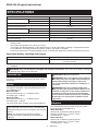
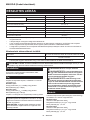
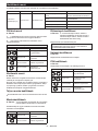
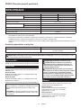
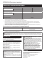
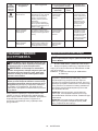
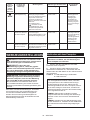
SPECIFICATIONS
Model: DFT060T DFT120T
Fastening torque Hard joint 2 - 6 N•m 4 - 12 N•m
Soft joint 2 - 6 N•m 4 - 12 N•m
No load speed (RPM) 50 - 1,000 min-1 50 - 700 min-1
Operating temperature range 0 °C - 40 °C
Dimensions (L x W x H) with BL1815N battery 206 mm x 75 mm x 247 mm
with BL1860B battery 206 mm x 75 mm x 263 mm
Rated voltage D.C. 18 V
Net weight 1.4 - 1.8 kg
Applicable USB cable 661432-2
• Duetoourcontinuingprogramofresearchanddevelopment,thespecicationshereinaresubjecttochange
without notice.
• Specicationsmaydierfromcountrytocountry.
• Theweightmaydierdependingontheattachment(s),includingthebatterycartridge.Thelightestandheavi-
est combination, according to EPTA-Procedure 01/2014, are shown in the table.
• Fastening torque and no load speed (RPM) can be controlled with application software designed for this tool.
Applicable battery cartridge and charger
Battery cartridge BL1815N / BL1820B / BL1830B / BL1840B / BL1850B / BL1860B
Charger DC18RC / DC18RD / DC18RE / DC18SD / DC18SE / DC18SF /
DC18SH / DC18WC
• Some of the battery cartridges and chargers listed above may not be available depending on your region of
residence.
WARNING: Only use the battery cartridges and chargers listed above. Use of any other battery cartridges
andchargersmaycauseinjuryand/orre.
Intended use
The tool is intended for screw driving in wood, metal
and plastic.
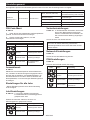
Noise
The typical A-weighted noise level determined accord-
ing to EN62841-2-2:
Model DFT060T
Sound pressure level (LpA) : 70 dB(A) or less
Uncertainty (K) : 3 dB (A)
Model DFT120T
Sound pressure level (LpA) : 70 dB(A) or less
Uncertainty (K) : 3 dB (A)
The noise level under working may exceed 80 dB (A).
NOTE: The declared noise emission value(s) has
been measured in accordance with a standard test
method and may be used for comparing one tool with
another.
NOTE: The declared noise emission value(s)
may also be used in a preliminary assessment of
exposure.
WARNING: Wear ear protection.
WARNING: The noise emission during actual
use of the power tool can dier from the declared
value(s) depending on the ways in which the
tool is used especially what kind of workpiece is
processed.
WARNING: Be sure to identify safety mea-
sures to protect the operator that are based on an
estimation of exposure in the actual conditions of
use (taking account of all parts of the operating
cycle such as the times when the tool is switched
o and when it is running idle in addition to the
trigger time).
Vibration
The vibration total value (tri-axial vector sum) deter-
mined according to EN62841-2-2:
Model DFT060T
Work mode: screwdriving without impact
Vibration emission (ah) : 2.5 m/s2 or less
Uncertainty (K) : 1.5 m/s2
Model DFT120T
Work mode: screwdriving without impact
Vibration emission (ah) : 2.5 m/s2 or less
Uncertainty (K) : 1.5 m/s2

6ENGLISH
NOTE: The declared vibration total value(s) has been
measured in accordance with a standard test method
and may be used for comparing one tool with another.
NOTE: The declared vibration total value(s) may also
be used in a preliminary assessment of exposure.
WARNING: The vibration emission during
actual use of the power tool can dier from the
declared value(s) depending on the ways in which
the tool is used especially what kind of workpiece
is processed.
WARNING: Be sure to identify safety mea-
sures to protect the operator that are based on an
estimation of exposure in the actual conditions of
use (taking account of all parts of the operating
cycle such as the times when the tool is switched
o and when it is running idle in addition to the
trigger time).
EC Declaration of Conformity
For European countries only
The EC declaration of conformity is included as Annex A
to this instruction manual.
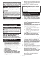
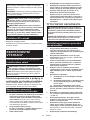
SAFETY WARNINGS
General power tool safety warnings
WARNING: Read all safety warnings, instruc-
tions, illustrations and specications provided
with this power tool. Failure to follow all instructions
listedbelowmayresultinelectricshock,reand/or
serious injury.
Save all warnings and instruc-
tions for future reference.
The term "power tool" in the warnings refers to your
mains-operated (corded) power tool or battery-operated
(cordless) power tool.
Cordless screwdriver safety
warnings
1. Hold the power tool by insulated gripping
surfaces, when performing an operation
where the fastener may contact hidden wiring.
Fasteners contacting a "live" wire may make
exposed metal parts of the power tool "live" and
could give the operator an electric shock.
2. Always be sure you have a rm footing.
Be sure no one is below when using the tool in
high locations.
3. Hold the tool rmly.
4. Keep hands away from rotating parts.
5. Do not touch the bit or the workpiece immedi-
ately after operation; they may be extremely
hot and could burn your skin.
6. Always secure workpiece in a vise or similar
hold-down device.
7. Make sure there are no electrical cables, water
pipes, gas pipes etc. that could cause a hazard
if damaged by use of the tool.
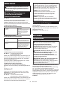
SAVE THESE INSTRUCTIONS.
WARNING: DO NOT let comfort or familiarity
with product (gained from repeated use) replace
strict adherence to safety rules for the subject
product.
MISUSE or failure to follow the safety rules stated
in this instruction manual may cause serious
personal injury.
Important safety instructions for
battery cartridge
1.
Before using battery cartridge, read all instruc-
tions and cautionary markings on (1) battery
charger, (2) battery, and (3) product using battery.
2. Do not disassemble or tamper with the battery
cartridge.Itmayresultinare,excessiveheat,
or explosion.
3. If operating time has become excessively
shorter, stop operating immediately. It may
result in a risk of overheating, possible burns
and even an explosion.
4.
If electrolyte gets into your eyes, rinse them out
with clear water and seek medical attention right
away. It may result in loss of your eyesight.
5. Do not short the battery cartridge:
(1) Do not touch the terminals with any con-
ductive material.
(2) Avoid storing battery cartridge in a con-
tainer with other metal objects such as
nails, coins, etc.
(3) Do not expose battery cartridge to water
or rain.
A battery short can cause a large current
ow, overheating, possible burns and even a
breakdown.
6. Do not store and use the tool and battery car-
tridge in locations where the temperature may
reach or exceed 50 °C (122 °F).
7. Do not incinerate the battery cartridge even if
it is severely damaged or is completely worn
out. The battery cartridge can explode in a re.
8. Do not nail, cut, crush, throw, drop the battery
cartridge, or hit against a hard object to the
battery cartridge. Such conduct may result in a
re,excessiveheat,orexplosion.
9. Do not use a damaged battery.
10.
The contained lithium-ion batteries are subject to
the Dangerous Goods Legislation requirements.
For commercial transports e.g. by third parties,
forwarding agents, special requirement on pack-
aging and labeling must be observed.
For preparation of the item being shipped, consult-
ing an expert for hazardous material is required.
Please also observe possibly more detailed
national regulations.
Tapeormaskoopencontactsandpackupthe
battery in such a manner that it cannot move
around in the packaging.

7ENGLISH
11. When disposing the battery cartridge, remove
it from the tool and dispose of it in a safe
place. Follow your local regulations relating to
disposal of battery.
12. Use the batteries only with the products
specied by Makita. Installing the batteries to
non-compliantproductsmayresultinare,exces-
sive heat, explosion, or leak of electrolyte.
13. If the tool is not used for a long period of time,
the battery must be removed from the tool.
14. During and after use, the battery cartridge may
take on heat which can cause burns or low
temperature burns. Pay attention to the han-
dling of hot battery cartridges.
15. Do not touch the terminal of the tool imme-
diately after use as it may get hot enough to
cause burns.
16. Do not allow chips, dust, or soil stuck into the
terminals, holes, and grooves of the battery
cartridge.Itmaycauseheating,catchingre,
burst and malfunction of the tool or battery car-
tridge, resulting in burns or personal injury.
17. Unless the tool supports the use near
high-voltage electrical power lines, do not use
the battery cartridge near high-voltage electri-
cal power lines. It may result in a malfunction or
breakdown of the tool or battery cartridge.
18. Keep the battery away from children.
SAVE THESE INSTRUCTIONS.
CAUTION: Only use genuine Makita batteries.
Use of non-genuine Makita batteries, or batteries that
have been altered, may result in the battery bursting
causingres,personalinjuryanddamage.Itwill
also void the Makita warranty for the Makita tool and
charger.
Tips for maintaining maximum
battery life
1. Charge the battery cartridge before completely
discharged. Always stop tool operation and
charge the battery cartridge when you notice
less tool power.
2. Never recharge a fully charged battery car-
tridge. Overcharging shortens the battery
service life.
3. Charge the battery cartridge with room tem-
perature at 10 °C - 40 °C (50 °F - 104 °F). Let
a hot battery cartridge cool down before
charging it.
4. When not using the battery cartridge, remove
it from the tool or the charger.
5. Charge the battery cartridge if you do not use
it for a long period (more than six months).
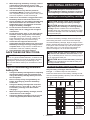
FUNCTIONAL DESCRIPTION
CAUTION: Always be sure that the tool is
switched o and the battery cartridge is removed
before adjusting or checking function on the tool.
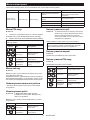
Installing or removing battery cartridge
CAUTION: Always switch o the tool before
installing or removing of the battery cartridge.
CAUTION: Hold the tool and the battery car-
tridge rmly when installing or removing battery
cartridge. Failure to hold the tool and the battery
cartridgermlymaycausethemtoslipoyourhands
and result in damage to the tool and battery cartridge
and a personal injury.
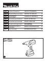
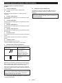
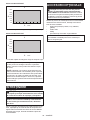
►Fig.1: 1. Red indicator 2. Button 3. Battery cartridge
To remove the battery cartridge, slide it from the tool
while sliding the button on the front of the cartridge.
To install the battery cartridge, align the tongue on the
battery cartridge with the groove in the housing and slip
it into place. Insert it all the way until it locks in place
with a little click. If you can see the red indicator as
showninthegure,itisnotlockedcompletely.
CAUTION: Always install the battery cartridge
fully until the red indicator cannot be seen. If not,
it may accidentally fall out of the tool, causing injury to
you or someone around you.
CAUTION: Do not install the battery cartridge
forcibly. If the cartridge does not slide in easily, it is
not being inserted correctly.
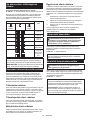
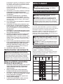
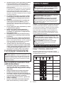
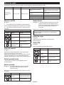
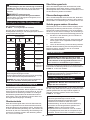
Indicating the remaining battery capacity
Only for battery cartridges with the indicator
►Fig.2: 1. Indicator lamps 2. Check button
Press the check button on the battery cartridge to indi-
cate the remaining battery capacity. The indicator lamps
light up for a few seconds.
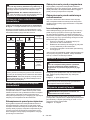
Indicator lamps Remaining
capacity
Lighted O Blinking
75% to 100%
50% to 75%
25% to 50%
0% to 25%
Charge the
battery.
The battery
may have
malfunctioned.

8ENGLISH
NOTE: Depending on the conditions of use and the
ambienttemperature,theindicationmaydierslightly
from the actual capacity.
NOTE:Therst(farleft)indicatorlampwillblinkwhen
the battery protection system works.
Tool / battery protection system
The tool is equipped with a tool/battery protection sys-
tem.Thissystemautomaticallycutsopowertothe
motor to extend tool and battery life. The tool will auto-
matically stop during operation if the tool or battery is
placed under one of the following conditions:
Overload protection
When the tool/battery is operated in a manner that
causes it to draw an abnormally high current, the tool
stopsautomatically.Inthissituation,turnthetoolo
and stop the application that caused the tool to become
overloaded. Then turn the tool on to restart.
Overheat protection
When the tool/battery is overheated, the tool stops
automatically. In this situation, let the tool/battery cool
before turning the tool on again.
Overdischarge protection
When the battery capacity is not enough, the tool stops
automatically. In this case, remove the battery from the
tool and charge the battery.
Protections against other causes
Protection system is also designed for other causes
that could damage the tool and allows the tool to stop
automatically. Take all the following steps to clear the
causes, when the tool has been brought to a temporary
halt or stop in operation.
1. Turnthetoolo,andthenturnitonagainto
restart.
2. Charge the battery(ies) or replace it/them with
recharged battery(ies).
3. Let the tool and battery(ies) cool down.
If no improvement can be found by restoring protection
system, then contact your local Makita Service Center.
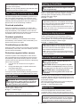
Switch action
WARNING: Before installing the battery car-
tridge into the tool, always check to see that the
switch trigger actuates properly and returns to
the "OFF" position when released.
Pull the switch trigger to start the tool. Release the
switch trigger to stop the tool.
►Fig.3: 1. Switch trigger
NOTE: The tool automatically stops temporarily to
saveoperationlogsafternishingfastening.
Lighting up front lamp
CAUTION: Do not look in the light or see the
source of light directly.
Pull the switch trigger to light up the lamp. The lamp
keeps on lighting while the switch trigger is being pulled.
The lamp goes out approximately 10 seconds after
releasing the switch trigger.
►Fig.4: 1. Lamp
NOTE: Pre-set lighting settings can be customized
in application preferences. For detailed information,
refer to the instruction manual supplied with the appli-
cation software designed for this tool.
NOTE:Useadryclothtowipethedirtothelensof
the lamp. Be careful not to scratch the lens of lamp, or
it may lower the illumination.
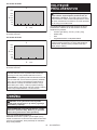
Turning on display screen
Pull the switch trigger to turn the display screen on.
The screen remains displayed while the switch trigger
isbeingpulled.Thescreengoesoapproximately60
seconds after releasing the switch trigger.
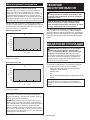
►Fig.5: 1. Display screen
NOTE: Default display settings can be customized
in application preferences. For detailed information,
refer to the instruction manual supplied with the appli-
cation software designed for this tool.
NOTE:Useadryclothtowipethedirtothedisplay
screen. Be careful not to scratch the screen, or it may
lower the illumination.
Reversing switch action
CAUTION: Always check the direction of
rotation before operation.
CAUTION:
Use the reversing switch only after
the tool comes to a complete stop. Changing the direc-
tion of rotation before the tool stops may damage the tool.
CAUTION: When not operating the tool,
always set the reversing switch lever to the neu-
tral position.
This tool has a reversing switch to change the direction
of rotation. Depress the reversing switch lever from the
A side for clockwise rotation or from the B side for coun-
terclockwise rotation.
When the reversing switch lever is in the neutral posi-
tion, the switch trigger cannot be pulled.
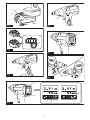
►Fig.6: 1. Reversing switch lever
Electric brake
This tool is equipped with an electric brake. If the tool
consistently fails to quickly stop after the switch trigger is
released, have the tool serviced at a Makita service center.
NOTE: An electric brake function can be activated or
deactivated in application preferences. For detailed
information, refer to the instruction manual supplied
with the application software designed for this tool.

9ENGLISH
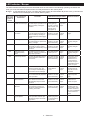
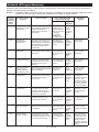
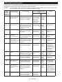
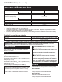
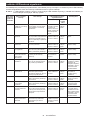
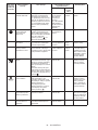
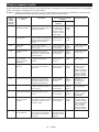
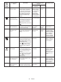
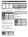
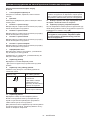
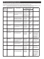
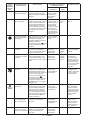
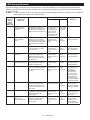
LED indicator / Beeper
The LED indicators and beeper become activated when the tool works in the following operating conditions and
notify you of the tool status and performance currently delivered on the control panel.
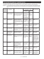
►Fig.7: 1. LED indicator A (in green, red, blue and yellow colors) 2. LED indicator B (in blue color) (* Not serve as
indicator for this model) 3. Error code 4. Status symbol
Error code
and status
symbol on
screen
Tool performance
and function Tool status LED indicators/beeper status Action to be taken
LED indicators Beeper
-Operation check for
indicators and beeper
The tool starts to verify indica-
tors and beeper operation soon
after the battery cartridge is
installed.
The LED indicator
brieylightsup
in green, red and
blue in order, and
then the front
lamp lights up.
A series of
very short
beeps
-
E00 Accidental start
prevention
The tool automatically stops
to avoid unintentional start-up
when the battery cartridge is
installed with the switch trigger
pulled.
The LED indicator
ashesinredand
green alternately.
A series
of short
beeps
Release the switch
trigger.
E01 Auto-stop The battery power becomes
low and it is time to replace the
battery cartridge.
The LED indicator
ashesinredand
green alternately.
A series
of short
beeps
Replace the battery
with fully charged
one.
E02 Anti-reset of controller The battery voltage drops
abnormally for some reason,
and the tool automatically stops
operation.
The LED indicator
ashesinredand
green alternately.
A series
of short
beeps
Replace the battery
with fully charged
one.
E03 Auto-stop for low
remaining battery
power
The battery power is almost
used up, and the tool automati-
cally stops operation.
The LED indicator
lights up in red.
A long
beep
Replace the battery
with fully charged
one.
E04 Overload protection The tool automatically stops to
protect against a continuous
overcurrent.
The LED indicator
ashesinredand
green alternately.
A series
of short
beeps
Remove the cause
of overload and
restart the tool. If
no improvement
is found, ask your
local Makita Service
Center for repair.
E05 Overheat protection The motor or controller gen-
erates excessive heat, and
the tool stops automatically to
protect the tool from damage.
The LED indicator
brieyashes
in red.
A series
of short
beeps
Remove the battery
cartridge immedi-
ately and cool the
tool down.
E06 Motor lock Motor lock has occurred, and
the tool automatically stops the
motor operation.
The LED indicator
ashesinredand
green alternately.
A series
of short
beeps
Release the switch
trigger and pull it
again.
E07 Motor or controller
failure detection
Motor or controller failure has
been detected, and the tool
automatically stops the motor
operation.
The LED indicator
ashesinredand
green alternately.
A series
of short
beeps
Ask your local
Makita Service
Center for repair.
E09 Torque sensor failure
detection
The torque sensor cannot
be monitored properly for a
number of technical reasons
including line breaks.
The LED indicator
ashesinredand
green alternately.
A series
of short
beeps
Remove the battery
cartridge and cool
the tool down. If the
indicator remains lit,
ask your local Makita
Service Center for
repair.
-Auto-stop with fasten-
ing completion
The tool automatically stops the
motor operation after the pre-
set fastening steps have been
completed.
The LED indicator
lights up in green
for approximately
one second.
- -

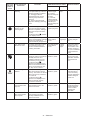
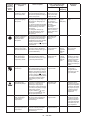
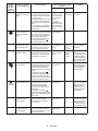
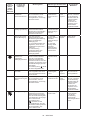
10 ENGLISH
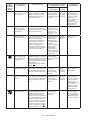
Error code
and status
symbol on
screen
Tool performance
and function Tool status LED indicators/beeper status Action to be taken
LED indicators Beeper
-Alertforinsucient
fastening
The tool raises an alert for
incomplete fastening under the
following operating conditions.
(1): The trigger switch is
released before the pre-set
fastening torque has been
achieved.
(2): The tool stops automati-
cally after classifying fastening
errors.
(1): The LED
indicator lights
up in red for
approximately two
seconds.
(2): The LED
indicatorashes
in yellow and red
alternately for
approximately two
seconds.
A long
beep
Retighten the screw.
Waiting function
between pre-set
fastening steps
The tool is sitting idle, after one
of the pre-set fastening steps
has been completed, waiting to
follow the next pre-set fasten-
ing step.
* A status symbol ( )ashes
in the display screen.
The LED indicator
lights up in green.
- -
-Low-battery alert The battery is becoming low on
power, and the battery cartridge
needs to be recharged or
replaced with fully charged one.
The LED indicator
slowlyashes
in red.
A series of
long beeps
Replace the battery
with fully charged
one.
-Error alert for heat
detection of motor
The motor temperature cannot
be monitored properly for a
number of technical reasons
including line breaks.
The LED indicator
brieyashes
in red.
A series
of short
beeps
Remove the battery
cartridge and cool
the tool down. If the
indicator remains lit,
ask your local Makita
Service Center for
repair.
Maintenance notice Maintenance notice will be
posted for optimum operational
reliability when the accu-
mulated maintenance count
reaches the pre-set number.
* A status symbol ( )
appears in the display screen
when the accumulated mainte-
nance count reaches the pre-
set “Stop Count” number.
The LED indicator
ashesinyellow.
-Reset the mainte-
nance count in the
application software
designed for this
tool.
Alert for storage
disabled
Up to 1,000 fastening result
data can be saved in the tool
memory. The number of unread
data in the memory reaches to
the maximum.
* A status symbol ( )
appears in the display screen
when the storage capacity
reaches the maximum.
The LED indicator
ashesinyellow.
-Load the fastening
result data saved
in the tool memory
using the application
software designed
for this tool.
-Error alert for data
communication with
computer
The tool raises an alert for
communication error in the
wired environment.
The LED indicator
ashesinyellow.
-Link the tool again
with the application
software designed
for the tool after
restarting the
application.
-Status indicator for
data communication
with computer
The tool informs that data
communication has been
securely established in the
wired environment.
The LED indicator
ashesingreen.
- -

11 ENGLISH
TOOL SETTINGS
CAUTION: Make sure to adjust tool settings
according to your applications and preferences
before use.
CAUTION: Perform trial fastening, using a
torque checker etc., if necessary, so as to verify if
the updated settings are successfully applied.
NOTICE: Install the application software
designed for this tool in your computer before
connecting the tool to the computer for the rst
time. For detailed information, refer to the installa-
tion manual supplied with the application software
designed for this tool.
A series of operation settings, including fastening
torque and no-load speed, can be adjusted via software
screen. Archiving and sharing tool preferences through
the software can enhance work performance.
Connecting with computer
NOTICE: Use the Makita genuine USB cable to
connect the tool with your computer.
1. Plug the USB cable into the USB port on your
computer.
2. Slide the USB cover open on top of the housing,
and then plug the other end of the USB cable into the
USB port on the tool.
►Fig.8: 1. USB cover 2. USB cable 3. USB port
NOTE: The LED indicator on top of the rear display
screenashesinyellowafteryourcomputerrec-
ognizes the tool plugged into the USB port. Launch
the application software on your computer, and the
LEDindicatorashesingreenafterdatacommuni-
cation between the devices has been successfully
established.
NOTE: While connected to your computer, the LED
indicatoronthetoolremainsashingingreenandno
switch operation is available.
NOTE: Slide the USB cover close on top of the hous-
ing each time after disconnecting the USB cable from
the USB port on the tool.

12 ENGLISH
Switch control on display panel and screen components
Buttons and descriptions on start screen
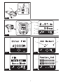
►Fig.9
1. LED indicator A
Lights up in green, red, blue and yellow colors.
2. Display screen
Displays and navigates you to the settings menu.
3. Up arrow button
Edit tool settings using four buttons on the panel
accordingly.
4. Down arrow button
Edit tool settings using four buttons on the panel
accordingly.
5. Left arrow button
Edit tool settings using four buttons on the panel
accordingly.
6. Right arrow button
Edit tool settings using four buttons on the panel
accordingly.
7. Information window
Upper row: Fastening torque set in the previous
operation
Lower row: Rotation angle set in the previous operation
8. Mode indicator
Displays the mode currently selected.
* Only “manual mode” is available for this tool.
9. Data communication status indicator
Status symbols Indicate data communication status as
follows:
Status symbol Communication status
Data communication not
established
* This symbol always
appears on the screen
during fastening
operation.
USB data communication
established
10. Job indicator
Displays the job number currently selected.
Up to 8 jobs can be stored in the tool memory using the
application software designed for this tool.
Job data includes settings information and operation
logs such as fastening torque and rotation speed.
NOTE: When the number zero appears on the
screen, no job data is saved in the tool. Create a job
using the application software designed for this tool.
11. Page number currently displayed on the
screen / Total page numbers
12. Data saving progress indicator
A status symbol ( ) appears in the display screen
while the tool settings and operation logs are being
saved in the tool memory.
NOTICE: Do not remove the battery cartridge
from the tool while any settings les and opera-
tion logs are being saved in the tool memory.

13 ENGLISH
Settings menu
The following settings menu options are available in the settings menu window.
Level 1 Level 2 Level 3 Level 4
Start menu (start
screen) PIN code menu Select menu
“Total Job” menu Total job settings
* Not available for this tool
“Manual Mode” menu Job settings
“History” menu History settings
“Network” menu Network settings
“PIN” menu PIN settings
PIN code menu
►Fig.10
1. On the start screen press and hold the right arrow
button to display the PIN code menu.
2. Enter the PIN codes to display the select menu.
NOTE: The default PIN codes are “0000”.
Button Action Application
Press Change digit position.
Press Change setting values.
Press and hold Conrmsetting
Press and hold Return to start screen
Select menu
►Fig.11
Select one of the menu options on the screen after you
enter the PIN successfully.
Press the up or down arrow button to scroll the select
menu screen. Then press the right arrow button to
display your preferred settings menu.
Total job settings
* This settings menu is not available for this tool.
Job settings
►Fig.12: 1. Job number you select 2. Total job num-
bers stored in tool memory
Select one of the jobs previously saved in the tool
memory.
Button Action Application
Press Change setting values.
Press and hold Conrmsetting
History settings
►Fig.13: 1. Total numbers of screws you have fas-
tenedsofarsincerstoperation2. Total
numbers of screws you have fastened after
previous maintenance
Learn your job history.
NOTE: Accumulated maintenance count can be
reset in your accordance in the application software
designed for this tool.
Network settings
►Fig.14
Learnyourdeviceidentication.
PIN settings
►Fig.15
Renew your PIN codes if the need arises.
Button Action Application
Press Change digit position.
Press Change setting values.
Press and hold Conrmsetting
Press and hold Return to start screen

14 ENGLISH
ASSEMBLY
CAUTION: Always be sure that the tool is
switched o and the battery cartridge is removed
before carrying out any work on the tool.
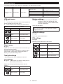
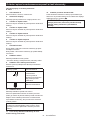
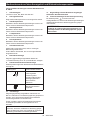
Installing or removing driver bit/
socket bit
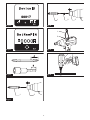
►Fig.16
Use only driver bit/socket bit that has inserting portion
showninthegure.Donotuseanyotherdriverbit/
socket bit.
For tool with shallow driver bit hole
A=12mm
B=9mm
Use only these type of driver
bit. Follow the procedure
1. (Note) Bit-piece is not
necessary.
For tool with deep driver bit hole
A=17mm
B=14mm
To install these types of driver
bits, follow the procedure 1.
A=12mm
B=9mm
To install these types of driver
bits, follow the procedure 2.
(Note) Bit-piece is necessary
for installing the bit.
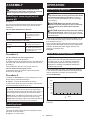
Procedure 1
For tool without one-touch type sleeve
►Fig.17: 1. Driver bit 2. Sleeve
To install the driver bit, pull the sleeve in the direction of
the arrow and insert the driver bit into the sleeve as far
as it will go.
Then release the sleeve to secure the driver bit.
For tool with one-touch type sleeve
To install the driver bit, insert the driver bit into the
sleeve as far as it will go.
Procedure 2
In addition to Procedure 1, insert the bit-piece into the
sleeve with its pointed end facing in.
►Fig.18: 1. Driver bit 2. Bit-piece 3. Sleeve
To remove the driver bit, pull the sleeve in the direction
of the arrow and pull the driver bit out.
NOTE:
If the driver bit is not inserted deep enough into
the sleeve, the sleeve will not return to its original posi-
tion and the driver bit will not be secured. In this case, try
re-inserting the bit according to the instructions above.
NOTE:
Whenitisdiculttoinsertthedriverbit,pullthe
sleeve and insert it into the sleeve as far as it will go.
NOTE: After inserting the driver bit, make sure that it
isrmlysecured.Ifitcomesout,donotuseit.
Installing hook
Optional accessory
The hook is useful to hang the tool. Install the hook to
the holes on the tool body.
►Fig.19: 1. Hook 2. Hole
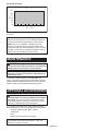
OPERATION
Screwdriving operation
CAUTION: Hold the tool rmly and place the
driver bit/socket bit securely over the screw head/
bolt head during fastening operation. Failure to
do so may cause mishandling of the tool resulting in
personal injury.
CAUTION: Make sure that the driver bit/
socket bit is placed straight over the screw head,
or the screw and driver bit/socket bit may be
damaged.
CAUTION: Keep hands away from the rotating
parts during operation. Failure to do so may cause
your hands to be caught in the moving parts, resulting
in personal injury.
Place the tip of the driver bit/socket bit straight over the
screw head/bolt head, apply pressure to the tool, and
then switch the tool on.
The tool automatically stops the motor when the output
torque reaches the target torque set in the application
software. Release the switch trigger after the tool
comes to a complete stop.
►Fig.20
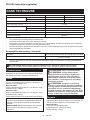
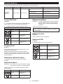
Limits of fastening capacity
NOTICE: Operating temperature range
Use the tool in the recommended ambient tempera-
ture range of 0 °C - 40 °C. Operation outside the
recommended temperature may reduce the tool
performance,resultingininsucientfasteningor
unstable output torque.
Use the tool within the limits of its fastening capacity.
If you use the tool beyond the limits, the output torque
may be reduced as a means of tool protection.
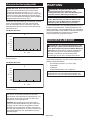
For model DFT060T
2.0 6.03.0 5.0
4.0
360°
300°
240°
180°
120°
60°
30°
1
3
2
N•m
1. Range of fastening capacity 2. Rotation angle
3. Torque

15 ENGLISH
For model DFT120T
4.0 12.06.0 10.0
8.0
360°
300°
240°
180°
120°
60°
30°
1
3
2
N•m
1. Range of fastening capacity 2. Rotation angle
3. Torque
NOTE: The rotation angle is the angle from the point
that the bolt is tightened in 50% of desired torque to
the point that the bolt is tightened in 100% torque.
NOTE: Use of a cold battery cartridge may give
warning for battery capacity by LED indicator and
beeper and stop the tool immediately, even if it is fully
charged. In this case, the fastening capacity may be
inferiortothespecicationonthismanual.
MAINTENANCE
CAUTION:
Always be sure that the tool is
switched o and the battery cartridge is removed before
attempting to perform inspection or maintenance.
NOTICE: Never use gasoline, benzine, thinner,
alcohol or the like. Discoloration, deformation or
cracks may result.
To maintain product SAFETY and RELIABILITY,
repairs, any other maintenance or adjustment should
be performed by Makita Authorized or Factory Service
Centers, always using Makita replacement parts.
OPTIONAL ACCESSORIES
CAUTION:
These accessories or attachments are
recommended for use with your Makita tool specied in
this manual. The use of any other accessories or attach-
ments might present a risk of injury to persons. Only use
accessory or attachment for its stated purpose.
If you need any assistance for more details regarding
these accessories, ask your local Makita Service Center.
• Protector (Natural, Red, Blue, Yellow)
• USB cable
• Hook
• Makita genuine battery and charger
NOTE: Some items in the list may be included in the
tool package as standard accessories. They may
dierfromcountrytocountry.

16 POLSKI
POLSKI (Instrukcja oryginalna)
DANE TECHNICZNE
Model: DFT060T DFT120T
Momentdokręcenia Złączkatwarda 2–6 N•m 4–12 N•m
Złączkamiękka 2–6 N•m 4–12 N•m
Prędkośćbezobciążenia(obr./min) 50–1 000 min-1 50–700 min-1
Zakres temperatury roboczej 0°C–40°C
Wymiary(dług.xszer.xwys.) z akumulatorem BL1815N 206 mm x 75 mm x 247 mm
z akumulatorem BL1860B 206 mm x 75 mm x 263 mm
Napięcieznamionowe Prądstały18V
Masa netto 1,4–1,8 kg
Odpowiedni kabel USB 661432-2
• Wzwiązkuzestaleprowadzonymprzeznasząrmęprogramembadawczo-rozwojowymniniejszedanemogą
uleczmianombezwcześniejszegopowiadomienia.
• Danetechnicznemogąróżnićsięwzależnościodkraju.
• Masamożebyćróżnawzależnościodosprzętu,wtymakumulatora.Wtabeliprzedstawionajestnajlżejszai
najcięższakonguracja,zgodniezprocedurąEPTA01/2014.
• Momentdokręceniaiprędkośćbezobciążenia(obr./min)możnaregulowaćprzyużyciuoprogramowaniaprze-
znaczonegodlategonarzędzia.
Kompatybilne akumulatory i ładowarki
Akumulator BL1815N / BL1820B / BL1830B / BL1840B / BL1850B / BL1860B
Ładowarka DC18RC / DC18RD / DC18RE / DC18SD / DC18SE / DC18SF /
DC18SH / DC18WC
• Pewnezwymienionychpowyżejakumulatorówiładowarekmogąbyćniedostępnewregioniezamieszkania
użytkownika.
OSTRZEŻENIE: Należy używać wyłącznie akumulatorów i ładowarek wymienionych powyżej.
Używanieinnychakumulatorówiładowarekmożestwarzaćryzykowystąpieniaobrażeńciałalubpożaru.
Przeznaczenie
Narzędziejestprzeznaczonedowkręcaniaśrubiwkrę-
tówwdrewnie,metaluitworzywachsztucznych.
Hałas
TypowyrównoważnypoziomdźwiękuAokreślonyw
oparciuonormęEN62841-2-2:
Model DFT060T
Poziomciśnieniaakustycznego(LpA): 70 dB(A) lub mniej
Niepewność(K):3dB(A)
Model DFT120T
Poziomciśnieniaakustycznego(LpA): 70 dB(A) lub mniej
Niepewność(K):3dB(A)
Poziomhałasupodczaspracymożeprzekraczać80dB(A).
WSKAZÓWKA:Deklarowanawartośćemisjihałasu
zostałazmierzonazgodniezestandardowąmetodą
testowąimożnająwykorzystaćdoporównywania
narzędzi.
WSKAZÓWKA:Deklarowanąwartośćemisjihałasu
możnatakżewykorzystaćwewstępnejocenie
narażenia.
OSTRZEŻENIE: Nosić ochronniki słuchu.
OSTRZEŻENIE: Poziom hałasu wytwa-
rzanego podczas rzeczywistego użytkowania
elektronarzędzia może się różnić od wartości
deklarowanej w zależności od sposobu użytko-
wania narzędzia, a w szczególności od rodzaju
obrabianego elementu.
OSTRZEŻENIE: W oparciu o szacowane
narażenie w rzeczywistych warunkach użytkowa-
nia należy określić środki bezpieczeństwa w celu
zapewnienia ochrony operatora (uwzględniając
wszystkie elementy cyklu działania, tj. czas, kiedy
narzędzie jest wyłączone i kiedy pracuje na biegu
jałowym, a także czas, kiedy jest włączone).
Drgania
Całkowitawartośćpoziomudrgań(sumawektoróww3
osiach)określonazgodnieznormąEN62841-2-2:
Model DFT060T
Trybpracy:wkręcaniebezudaru
Emisjadrgań(ah): 2,5 m/s2 lub mniej
Niepewność(K):1,5m/s2

17 POLSKI
Model DFT120T
Trybpracy:wkręcaniebezudaru
Emisjadrgań(ah): 2,5 m/s2 lub mniej
Niepewność(K):1,5m/s2
WSKAZÓWKA:Deklarowanawartośćpoziomu
drgańzostałazmierzonazgodniezestandardową
metodątestowąimożnająwykorzystaćdoporówny-
wanianarzędzi.
WSKAZÓWKA:Deklarowanąwartośćpoziomu
drgańmożnatakżewykorzystaćwewstępnejocenie
narażenia.
OSTRZEŻENIE: Drgania wytwarzane pod-
czas rzeczywistego użytkowania elektronarzędzia
mogą się różnić od wartości deklarowanej w
zależności od sposobu użytkowania narzędzia,
a w szczególności od rodzaju obrabianego
elementu.
OSTRZEŻENIE: W oparciu o szacowane
narażenie w rzeczywistych warunkach użytkowa-
nia należy określić środki bezpieczeństwa w celu
zapewnienia ochrony operatora (uwzględniając
wszystkie elementy cyklu działania, tj. czas, kiedy
narzędzie jest wyłączone i kiedy pracuje na biegu
jałowym, a także czas, kiedy jest włączone).
Deklaracja zgodności WE
Dotyczy tylko krajów europejskich
DeklaracjazgodnościWEjestdołączonajakozałącznik
Adoniniejszejinstrukcjiobsługi.
OSTRZEŻENIA
DOTYCZĄCE
BEZPIECZEŃSTWA
Ogólne zasady bezpiecznej
eksploatacji elektronarzędzi
OSTRZEŻENIE: Należy zapoznać się z
ostrzeżeniami dotyczącymi bezpieczeństwa,
instrukcjami, ilustracjami i danymi technicz-
nymi dołączonymi do tego elektronarzędzia.
Niezastosowaniesiędopodanychponiżejinstrukcji
możeprowadzićdoporażeniaprądem,pożarui/lub
poważnychobrażeńciała.
Wszystkie ostrzeżenia i instruk-
cje należy zachować do wykorzy-
stania w przyszłości.
Pojęcie„elektronarzędzie”,występującewwymienio-
nychtuostrzeżeniach,odnosisiędoelektronarzędzia
zasilanegozsiecielektrycznej(zprzewodemzasilają-
cym)lubdoelektronarzędziaakumulatorowego(bez
przewoduzasilającego).
Ostrzeżenia dotyczące
bezpieczeństwa dla wkrętarki
bezprzewodowej
1. Trzymać elektronarzędzie za izolowane
powierzchnie rękojeści podczas wykonywa-
nia prac, przy których element złączny może
dotknąć niewidocznej instalacji elektrycznej.
Zetknięcieelementówzłącznychzprzewodem
elektrycznymznajdującymsiępodnapięciemspo-
woduje,żeodsłonięteelementymetalowenarzę-
dziarównieżznajdąsiępodnapięciem,grożąc
porażeniemoperatoraprądemelektrycznym.
2. Podczas pracy należy zadbać o stabilne opar-
cie dla nóg.
W przypadku pracy na wysokości upewnić się,
że na dole nie przebywają żadne osoby.
3. Narzędzie należy trzymać mocno i pewnie.
4. Trzymać ręce z dala od części obrotowych.
5. Nie dotykać wiertła ani części obrabianej od
razu po zakończeniu danej operacji; mogą one
być bardzo gorące i spowodować oparzenie
skóry.
6. Element obrabiany należy zawsze mocować w
imadle lub podobnym uchwycie.
7. Należy się upewnić, że w obszarze pracy
nie ma żadnych przewodów elektrycznych,
rur instalacji wodnej, rur z gazem itp., które
mogłyby stanowić zagrożenie po uszkodzeniu
przez narzędzie.
ZACHOWAĆ NINIEJSZE
INSTRUKCJE.
OSTRZEŻENIE: NIE WOLNO pozwolić, aby
wygoda lub rutyna (nabyta w wyniku wielokrot-
nego używania urządzenia) zastąpiły ścisłe prze-
strzeganie zasad bezpieczeństwa obsługi.
NIEWŁAŚCIWE UŻYTKOWANIE narzędzia lub
niestosowanie się do zasad bezpieczeństwa
podanych w niniejszej instrukcji obsługi może
prowadzić do poważnych obrażeń ciała.
Ważne zasady bezpieczeństwa
dotyczące akumulatora
1. Przed użyciem akumulatora zapoznać się ze
wszystkimi instrukcjami i znakami ostrze-
gawczymi na (1) ładowarce, (2) akumulatorze
i (3) produkcie, w którym będzie używany
akumulator.
2. Nie rozmontowywać ani modykować akumu-
latora.Możetospowodowaćpożar,przegrzanie
lub wybuch.
3. Jeśli czas działania uległ znacznemu skróce-
niu, należy natychmiast przerwać pracę. Może
bowiem dojść do przegrzania, ewentualnych
poparzeń, a nawet eksplozji.
4. W przypadku przedostania się elektrolitu do
oczu, przemyć je czystą wodą i niezwłocznie
uzyskać pomoc lekarską. Może on bowiem
spowodować utratę wzroku.

18 POLSKI
5. Nie doprowadzać do zwarcia akumulatora:
(1) Nie dotykać styków materiałami przewo-
dzącymi prąd.
(2) Unikać przechowywania akumulatora w
pojemniku z metalowymi przedmiotami,
takimi jak gwoździe, monety itp.
(3)
Chronić akumulator przed deszczem lub wodą.
Zwarcie prowadzi do przepływu prądu elek-
trycznego o dużym natężeniu i przegrzania
akumulatora, co w konsekwencji może grozić
poparzeniami a nawet awarią urządzenia.
6. Narzędzia i akumulatora nie wolno przechowy-
wać ani używać w miejscach, w których tempe-
ratura osiąga bądź przekracza 50°C (122°F).
7. Akumulatorów nie wolno spalać, również tych
poważnie uszkodzonych lub całkowicie zuży-
tych. Akumulator może eksplodować w ogniu.
8.
Nie należy przecinać ani zgniatać akumulatora,
wbijać w niego gwoździ, rzucać nim, upuszczać, ani
uderzać akumulatorem o twarde obiekty.Takiedziała-
niemożespowodowaćpożar,przegrzanielubwybuch.
9. Nie wolno używać uszkodzonego akumulatora.
10. Stanowiące wyposażenie akumulatory lito-
wo-jonowe podlegają przepisom dotyczącym
produktów niebezpiecznych.
Napotrzebytransportukomercyjnego,np.świad-
czonegoprzezrmytrzecieczyspedycyjne,
należyprzestrzegaćspecjalnychwymagańw
zakresie pakowania i oznaczania etykietami.
Przygotowanieproduktudowysyłkiwymagaskon-
sultowaniasięzespecjalistąds.materiałówniebez-
piecznych.Należytakżeprzestrzegaćprzepisów
krajowych,któremogąbyćbardziejszczegółowe.
Zakleićtaśmąlubzaślepićotwartestykiakumula-
toraorazzabezpieczyćgo,abyniemógłsięprze-
suwaćwopakowaniu.
11.
Jeśli zajdzie konieczność utylizacji akumulatora,
należy wyjąć go z narzędzia i przekazać w bez-
pieczne miejsce. Postępować zgodnie z przepisami
lokalnymi dotyczącymi utylizacji akumulatorów.
12.
Używać akumulatorów tylko z produktami określo-
nymi przez rmę Makita.Zastosowanieakumulatorów
wniezgodnychproduktachmożespowodowaćpożar,
przegrzanie, wybuch lub wyciek elektrolitu.
13. Jeśli narzędzie nie będzie używane przez dłuż-
szy czas, należy wyjąć z niego akumulator.
14. Przed użyciem akumulatora i po jego użyciu
akumulator może pozostawać nagrzany, co
może spowodować poparzenia lub poparzenia
w niskiej temperaturze. Z gorącym akumulato-
rem należy obchodzić się ostrożnie.
15. Nie należy dotykać styku narzędzia bezpośred-
nio po jego użyciu, ponieważ może on być na
tyle gorący, że spowoduje oparzenia.
16.
Nie należy dopuszczać, aby wióry, kurz lub brud gro-
madziły się na stykach, w otworach i rowkach aku-
mulatora.Możetodoprowadzićdoprzegrzania,pożaru,
wybuchulubuszkodzenianarzędzialubakumulatora,co
możespowodowaćoparzenialubobrażeniaciała.
17. Jeśli narzędzie nie jest przeznaczone do
użytku w pobliżu linii wysokiego napięcia,
nie należy korzystać z akumulatora w ich
sąsiedztwie.Możetospowodowaćnieprawidło-
wościwdziałaniulubuszkodzenienarzędzialub
akumulatora.
18. Przechowywać akumulator w miejscu niedo-
stępnym dla dzieci.
ZACHOWAĆ NINIEJSZE
INSTRUKCJE.
PRZESTROGA:
Używać wyłącznie oryginalnych
akumulatorów rmy Makita.Używanienieoryginalnych
akumulatorówrminnychniżMakitalubakumulatorów,
którezostałyzmodykowane,możespowodowaćwybuch
akumulatoraipożar,obrażeniaciałaorazzniszczenie
mienia.Stanowitorównieżnaruszeniewarunkówgwarancji
rmyMakitadotyczącychnarzędziaiładowarki.
Wskazówki dotyczące zacho-
wania maksymalnej trwałości
akumulatora
1.
Akumulator należy naładować zanim zostanie do końca
rozładowany. Po zauważeniu spadek mocy narzędzia
należy przerwać pracę i naładować akumulator.
2. Nie wolno ładować powtórnie w pełni nałado-
wanego akumulatora. Przeładowanie akumula-
tora skraca jego trwałość.
3.
Akumulator należy ładować w temperaturze poko-
jowej w przedziale 10–40°C (50–104°F). W przy-
padku gorącego akumulatora przed przystąpie-
niem do ładowania należy poczekać, aż ostygnie.
4. Jeśli akumulator nie jest używany, należy go
wyjąć z narzędzia lub ładowarki.
5. Akumulatory niklowo-wodorkowe należy nała-
dować po okresie długiego nieużytkowania
(dłuższego niż sześć miesięcy).
OPIS DZIAŁANIA
PRZESTROGA: Przed przystąpieniem do regu-
lacji lub przeglądu narzędzia upewnić się, że jest
ono wyłączone, a akumulator został wyjęty.
Wkładanie i wyjmowanie akumulatora
PRZESTROGA: Przed włożeniem lub wyjęciem
akumulatora należy zawsze wyłączyć narzędzie.
PRZESTROGA: Podczas wkładania lub wyjmo-
wania akumulatora należy mocno trzymać narzę-
dzie i akumulator.Wprzeciwnymraziemogąsięone
wyślizgnąćzrąk,powodującuszkodzenienarzędzia
lubakumulatoraiobrażeniaciała.
►Rys.1: 1.Czerwonywskaźnik2. Przycisk
3. Akumulator
Abywyjąćakumulator,przesuńprzyciskznajdującysię
wprzedniejjegoczęściiwysuńakumulator.
Abywłożyćakumulator,wyrównaćwystępnaakumu-
latorzezrowkiemwobudowieiwsunąćgonaswoje
miejsce.Akumulatornależywsunąćdooporu,ażsię
zatrzaśnienamiejscu,cojestsygnalizowanedelikat-
nymkliknięciem.Jeślijestwidocznyczerwonywskaźnik
pokazanynarysunku,akumulatorniezostałcałkowicie
zablokowany.

19 POLSKI
PRZESTROGA:
Akumulator należy włożyć do
końca, tak aby czerwony wskaźnik nie był widoczny. W
przeciwnymraziemożeprzypadkowowypaśćznarzędzia,
powodującobrażeniaoperatoralubosóbpostronnych.
PRZESTROGA: Nie wkładać akumulatora na
siłę.Jeśliakumulatorniedajesięswobodniewsunąć,
oznaczato,żezostałwłożonynieprawidłowo.
Wskazanie stanu naładowania
akumulatora
Tylko w przypadku akumulatorów ze wskaźnikiem
►Rys.2: 1.Lampkiwskaźnika2. Przycisk kontrolny
Nacisnąćprzyciskkontrolnynaakumulatorzewcelu
wyświetleniastanunaładowaniaakumulatora.Lampki
wskaźnikazaświecąsięprzezkilkasekund.
Lampki wskaźnika Pozostała
energia
akumulatora
Świeci się Wyłączony Miga
75–100%
50–75%
25–50%
0–25%
Naładować
akumulator.
Akumulator
możenie
działać
poprawnie.
WSKAZÓWKA:
Zależnieodwarunkówużytkowaniaitem-
peraturyotoczenia,wskazywanypoziommożenieznacznie
sięróżnićodrzeczywistegostanunaładowaniaakumulatora.
WSKAZÓWKA: Pierwsza (skrajnie po lewej stronie)
lampkawskaźnikamiga,gdyukładzabezpieczenia
akumulatora jest aktywny.
Układ zabezpieczenia narzędzia/
akumulatora
Narzędziejestwyposażonewukładzabezpieczenia
narzędzia/akumulatora.Układautomatycznieodcina
zasilaniesilnikawceluwydłużeniatrwałościnarzędzia
iakumulatora.Narzędziezostanieautomatycznie
zatrzymanepodczaspracywnastępującychsytuacjach
związanychznarzędziemlubakumulatorem:
Zabezpieczenie przed przeciążeniem
Wprzypadkuużytkowanianarzędzia/akumulatoraw
sposóbpowodującynadmierniewysokipobórprądu
narzędziezostanieautomatyczniezatrzymane.Wtakiej
sytuacjinależywyłączyćnarzędzieizaprzestaćwyko-
nywaniaczynnościpowodującejprzeciążenienarzę-
dzia.Następnienależywłączyćnarzędziewcelujego
ponownego uruchomienia.
Zabezpieczenie przed przegrzaniem
Wprzypadkuprzegrzanianarzędzia/akumulatora
narzędziewyłączysięautomatycznie.Wtakiejsytuacji
należyodczekać,ażnarzędzie/akumulatorostygnie
przedponownymwłączeniemnarzędzia.
Zabezpieczenie przed nadmiernym
rozładowaniem
Gdystannaładowaniaakumulatorastaniesięzbyt
niski,narzędziezostanieautomatyczniezatrzymane.
Wtakiejsytuacjinależywyjąćakumulatorznarzędziai
naładowaćgo.
Inne zabezpieczenia
Układzabezpieczającyjestprzeznaczonydoochrony
przedinnymiprzyczynami,któremogądoprowadzić
douszkodzenianarzędziaiumożliwiaautomatyczne
zatrzymanienarzędzia.Należywykonaćponiższekroki,
abyusunąćprzyczynytymczasowegowstrzymanialub
zatrzymaniapracynarzędzia.
1. Wyłączyćnarzędzie,anastępniewłączyćje
ponownie w celu zrestartowania.
2. Naładowaćakumulatorylubzastąpićje(lubjeden
znich)naładowanymiakumulatorami.
3. Pozostawićnarzędzieiakumulator(akumulatory)
doostygnięcia.
Jeśliprzywróceniedziałaniaukładuzabezpieczającego
nieprzynosipozytywnychefektów,należyskontakto-
waćsięzcentrumserwisowymMakita.
Działanie przełącznika
OSTRZEŻENIE: Przed włożeniem akumu-
latora do narzędzia należy zawsze sprawdzić,
czy spust przełącznika działa prawidłowo i
czy powraca do położenia wyłączenia po jego
zwolnieniu.
Pociągnąćspustprzełącznika,abyuruchomićnarzę-
dzie.Zwolnićspustprzełącznika,abyzatrzymać
narzędzie.
►Rys.3: 1.Spustprzełącznika
WSKAZÓWKA:Pozakończeniudokręcanianarzę-
dzieautomatyczniezatrzymujesiętymczasowow
celuzapisaniadziennikówdziałania.
Włączanie przedniej lampki
PRZESTROGA: Nie patrzeć na światło ani
bezpośrednio na źródło światła.
Wceluwłączenialampkinależypociągnąćzaspust
przełącznika.Lampkaświeci,dopókispustprzełącznika
jestnaciskany.Lampkawyłączasiępookoło10sod
zwolnieniaspustuprzełącznika.
►Rys.4: 1. Lampka

20 POLSKI
WSKAZÓWKA:Predeniowaneustawieniaoświe-
tleniamożnazmodykowaćwpreferencjachopro-
gramowania.Szczegółoweinformacjeznajdująsię
winstrukcjiobsługidołączonejdooprogramowania
przeznaczonegodlategonarzędzia.
WSKAZÓWKA:Abyusunąćzabrudzeniazklosza
lampki,należyużyćsuchejszmatki.Uważać,abynie
zarysowaćkloszalampki,gdyżmożetozmniejszyć
natężenieoświetlenia.
Włączanie wyświetlacza
Wceluwłączeniawyświetlaczanależypociągnąć
spustprzełącznika.Wyświetlaczpozostajewłączony,
gdyspustprzełącznikajestwciśnięty.Wyświetlacz
gaśniepookoło60sekundachodzwolnieniaspustu
przełącznika.
►Rys.5: 1.Wyświetlacz
WSKAZÓWKA:Domyślneustawieniawyświetlacza
możnazmodykowaćwpreferencjachoprogramowa-
nia.Szczegółoweinformacjeznajdująsięwinstrukcji
obsługidołączonejdooprogramowaniaprzeznaczo-
negodlategonarzędzia.
WSKAZÓWKA:Abyusunąćzabrudzeniazwyświe-
tlacza,należyużyćsuchejszmatki.Uważać,abynie
zarysowaćwyświetlacza,gdyżmożetozmniejszyć
poziompodświetlenia.
Działanie przełącznika zmiany
kierunku obrotów
PRZESTROGA: Przed przystąpieniem do pracy
należy zawsze sprawdzić ustawiony kierunek
obrotów.
PRZESTROGA: Przełącznika zmiany kie-
runku obrotów można użyć tylko po całkowitym
zatrzymaniu narzędzia. Zmiana kierunku obro-
tówprzedzatrzymaniemsięnarzędziagrozijego
uszkodzeniem.
PRZESTROGA: Gdy narzędzie nie jest uży-
wane, należy zawsze ustawić dźwignię prze-
łącznika zmiany kierunku obrotów w położeniu
neutralnym.
Omawianenarzędziejestwyposażonewprzełącznik
umożliwiającyzmianękierunkuobrotów.Wceluuzy-
skaniaobrotówwprawąstronęnależywcisnąćdźwi-
gnięprzełącznikazmianykierunkuobrotówpostronie
A,natomiastabyuzyskaćobrotywlewąstronę,należy
wcisnąćdźwignięprzełącznikapostronieB.
Gdydźwigniaprzełącznikazmianykierunkuobrotów
znajdujesięwpołożeniuneutralnym,spustprzełącz-
nika jest zablokowany.
►Rys.6: 1.Dźwigniaprzełącznikazmianykierunku
obrotów
Hamulec elektryczny
Narzędziejestwyposażonewhamulecelektryczny.
Jeślinarzędzieczęstoniezatrzymujesięodrazupo
zwolnieniuspustuprzełącznika,należyzlecićnaprawę
narzędziaserwisowirmyMakita.
WSKAZÓWKA: W preferencjach oprogramowania
możnawłączyćlubwyłączyćfunkcjęhamulcaelek-
trycznego.Szczegółoweinformacjeznajdująsięw
instrukcjiobsługidołączonejdooprogramowania
przeznaczonegodlategonarzędzia.
Pagina se încarcă ...
Pagina se încarcă ...
Pagina se încarcă ...
Pagina se încarcă ...
Pagina se încarcă ...
Pagina se încarcă ...
Pagina se încarcă ...
Pagina se încarcă ...
Pagina se încarcă ...
Pagina se încarcă ...
Pagina se încarcă ...
Pagina se încarcă ...
Pagina se încarcă ...
Pagina se încarcă ...
Pagina se încarcă ...
Pagina se încarcă ...
Pagina se încarcă ...
Pagina se încarcă ...
Pagina se încarcă ...
Pagina se încarcă ...
Pagina se încarcă ...
Pagina se încarcă ...
Pagina se încarcă ...
Pagina se încarcă ...
Pagina se încarcă ...
Pagina se încarcă ...
Pagina se încarcă ...
Pagina se încarcă ...
Pagina se încarcă ...
Pagina se încarcă ...
Pagina se încarcă ...
Pagina se încarcă ...
Pagina se încarcă ...
Pagina se încarcă ...
Pagina se încarcă ...
Pagina se încarcă ...
Pagina se încarcă ...
Pagina se încarcă ...
Pagina se încarcă ...
Pagina se încarcă ...
Pagina se încarcă ...
Pagina se încarcă ...
Pagina se încarcă ...
Pagina se încarcă ...
Pagina se încarcă ...
Pagina se încarcă ...
Pagina se încarcă ...
Pagina se încarcă ...
Pagina se încarcă ...
Pagina se încarcă ...
Pagina se încarcă ...
Pagina se încarcă ...
Pagina se încarcă ...
Pagina se încarcă ...
Pagina se încarcă ...
Pagina se încarcă ...
Pagina se încarcă ...
Pagina se încarcă ...
Pagina se încarcă ...
Pagina se încarcă ...
Pagina se încarcă ...
Pagina se încarcă ...
Pagina se încarcă ...
Pagina se încarcă ...
Pagina se încarcă ...
Pagina se încarcă ...
Pagina se încarcă ...
Pagina se încarcă ...
Pagina se încarcă ...
Pagina se încarcă ...
Pagina se încarcă ...
Pagina se încarcă ...
Pagina se încarcă ...
Pagina se încarcă ...
Pagina se încarcă ...
Pagina se încarcă ...
Pagina se încarcă ...
Pagina se încarcă ...
Pagina se încarcă ...
Pagina se încarcă ...
-
 1
1
-
 2
2
-
 3
3
-
 4
4
-
 5
5
-
 6
6
-
 7
7
-
 8
8
-
 9
9
-
 10
10
-
 11
11
-
 12
12
-
 13
13
-
 14
14
-
 15
15
-
 16
16
-
 17
17
-
 18
18
-
 19
19
-
 20
20
-
 21
21
-
 22
22
-
 23
23
-
 24
24
-
 25
25
-
 26
26
-
 27
27
-
 28
28
-
 29
29
-
 30
30
-
 31
31
-
 32
32
-
 33
33
-
 34
34
-
 35
35
-
 36
36
-
 37
37
-
 38
38
-
 39
39
-
 40
40
-
 41
41
-
 42
42
-
 43
43
-
 44
44
-
 45
45
-
 46
46
-
 47
47
-
 48
48
-
 49
49
-
 50
50
-
 51
51
-
 52
52
-
 53
53
-
 54
54
-
 55
55
-
 56
56
-
 57
57
-
 58
58
-
 59
59
-
 60
60
-
 61
61
-
 62
62
-
 63
63
-
 64
64
-
 65
65
-
 66
66
-
 67
67
-
 68
68
-
 69
69
-
 70
70
-
 71
71
-
 72
72
-
 73
73
-
 74
74
-
 75
75
-
 76
76
-
 77
77
-
 78
78
-
 79
79
-
 80
80
-
 81
81
-
 82
82
-
 83
83
-
 84
84
-
 85
85
-
 86
86
-
 87
87
-
 88
88
-
 89
89
-
 90
90
-
 91
91
-
 92
92
-
 93
93
-
 94
94
-
 95
95
-
 96
96
-
 97
97
-
 98
98
-
 99
99
-
 100
100


în alte limbi
- slovenčina: Makita DFT060T Používateľská príručka
- polski: Makita DFT060T Instrukcja obsługi
Lucrări conexe
-
Makita DFL651F Manual de utilizare
-
-
-
Makita DFL020F Manual de utilizare
-
Makita DFL202 Manual de utilizare
-
-
Makita DTW300 Manual de utilizare
-
-
-
Makita DTW700, DTW701 Cordless Impact Wrench Manual de utilizare