STEINEL IR Quattro SLIM XS 4m COM1 Manual de utilizare
- Tip
- Manual de utilizare

STEINEL Vertrieb GmbH
Dieselstraße 80-84
33442 Herzebrock-Clarholz
Tel: +49/5245/448-188
www.steinel.de
Contact
www.steinel.de/contact
110064702 02/2019_A Technische Änderungen vorbehalten. / Subject to technical modification without notice.
DEGBFRNLITESPTSEDKFINOGRTRHUCZSKPLROSIHREELTLVRUBG
IR Quattro Slim XS COM1
Information
000000000 07/2013 Technische Änderungen vorbehalten.
RUS CN BG LV LT EST HR SLO RO PL SK CZ H TR GR N FIN DK S P E I NL FGB D
STL-7384-16_IR QUATTRO SLIM XS_BDAL_A6.indd 1 02.03.17 15:20
CN

- 2 - - 3 -
DE . . . . . . 5
GB . . . . . 11
FR . . . . . 17
NL . . . . . 23
IT . . . . . . 29
ES . . . . . 35
PT . . . . . 41
SE . . . . . 47
DK . . . . . 52
FI . . . . . . 57
NO . . . . . 62
GR . . . . . 67
TR . . . . . 73
HU . . . . . 78
CZ . . . . . 84
SK . . . . . 90
PL . . . . . 96
RO . . . . 102
SI . . . . . 108
HR . . . . 114
EE . . . . 120
LT . . . . . 126
LV . . . . . 132
RU . . . . 138
BG . . . . 144
CN . . . . 150
Textteil beachten!
Follow written instructions!
Suivre les instructions ci-après !
Tekstpassage in acht nemen!
Osservare il testo!
¡Obsérvese la información
textual!
Siga as instruções escritas
Följ den skriftliga
montageinstruktionen.
Følg de skriftlige
instruktioner!
Huomioi tekstiosa!
Se tekstdelen!
Τηρείτε γραπτές οδηγίες!
Yazılı talimatlara uyunuz!
A szöveges utasításokat
tartsa meg!
Dodržujte písemné pokyny!
Dodržiavajte písomné
informácie!
Postępować zgodnie
zinstrukcją!
Respectai instruciunile
următoare!
Upoštevajte besedilo!
Pridržavajte se uputa!
Järgige tekstiosa!
Atsižvelgti į rašytines
instrukcijas!
Pievērsiet uzmanību
teksta daļai!
Соблюдать текстовую
инструкцию!
Прочетете инструкциите!
遵守文字说明要求!
...
4.1
5
I
O
SPN
P
< 50m
< 50m
< 50m < 50m
L
L
N
N
LL
SPN
LL
SPN
LL
SPN
LL
SPN
LL
SPN
LL
SPN
LL
L
N
L
N
5.1
< 4 m
2,8 m
5.2
~ 4 m
~ 4 m
5.3
4.1
5
I
O
SPN
P
< 50m
< 50m
< 50m < 50m
L
L
N
N
LL
SPN
LL
SPN
LL
SPN
LL
SPN
LL
SPN
LL
SPN
LL
L
N
L
N
5.1
< 4 m
2,8 m
5.2
~ 4 m
~ 4 m
5.3
3.1
3.2
Ø 94,4
80
49
80
55
3.3
C
A
B
D
E
LL
4

- 4 - - 5 -
DE
1. Zu diesem Dokument
Bitte sorgfältig lesen und
aufbewahren!
– Urheberrechtlich geschützt.
Nachdruck, auch auszugsweise,
nur mit unserer Genehmigung.
– Änderungen, die dem tech-
nischen Fortschritt dienen,
vorbehalten.
Symbolerklärung
Warnung vor Gefahren!
Verweis auf Textstellen im
Dokument.
2. Allgemeine
Sicherheitshinweise
!Vor allen Arbeiten am Gerät
die Spannungszufuhr
unterbrechen!
• Bei der Montage muss die anzu-
schließende elektrische Leitung
spannungsfrei sein. Daher als
Erstes Strom abschalten und
Spannungsfreiheit mit einem
Spannungsprüfer überprüfen.
• Bei der Installation des Sensors
handelt es sich um eine Arbeit
an der Netzspannung. Sie muss
daher fachgerecht nach den
landesüblichen Installationsvor-
schriften und Anschlussbedingun-
gen durchgeführt werden.
• Nur original Ersatzteile verwenden.
• Reparaturen dürfen nur durch
Fachwerkstätten durchgeführt
werden.
• Hinweis: Leitung S des externen
Tasters ist nicht dazu bestimmt
Verbrauchern als Neutralleiteran-
schluss zu dienen.
3. IR Quattro SLIM XS COM1
Bestimmungsgemäßer Gebrauch
– Sensorschalter nur zur Decken-
montage im Innenbereich
geeignet.
– Gerätedose mit min. 57 mm Tiefe
erforderlich.
Leitungslänge zwischen Sensor und
Taster < 50 m.
Alle Funktionseinstellungen werden
über die optionalen Fernbedienungen
RC8, RC5 oder die Smart Remote
vorgenommen. (➜ "8. Zubehör")
Lieferumfang (Abb. 3.1)
Produktmaße (Abb. 3.2)
Geräteübersicht (Abb. 3.3)
A Sensormodul
B Designblende
C Sensorlinse
D+E Anschlussklemme
4. Installation
• Stromversorgung abschalten
(Abb. 4.1)
Für die Verdrahtung der Sensorschal-
ter gilt: Nach VDE 0100520 Abschnitt
6 darf für die Verdrahtung zwischen
Sensor und EVG eine Mehrfach-
schaltung verwendet werden, die
sowohl die Netzspannungsleitungen
wie auch die Steuerleitungen enthält
(z.B. NYM 5×1,5 mm²). Der Klemm-
bereich der Netzanschlussklemme ist
für maximal 2×2,5 mm² ausgelegt.
!
5.4
57
ø 68
5.5
S P N
L L
5.6
6
6.1
75%60%
6.3
I
O
6.2
100%
75%
60%
5.4
57
ø 68
5.5
S P N
L L
5.6
6
6.1
75%60%
6.3
I
O
6.2
100%
75%
60%
...

- 6 - - 7 -
Die Netzzuleitung besteht aus
einem 3-adrigen Kabel (max. Ø der
Leitungen 15-19 mm):
L = Phase (meistens schwarz
oder braun)
N = Neutralleiter (meistens blau)
PE = Schutzleiter
(meistens grün/gelb)
P = Zur Verbindung mehrerer
Bewegungsmelder
L' = Geschaltete Phase (meistens
schwarz, braun oder grau)
S = Schalter/Taster
Wichtig:
Ein Vertauschen der Anschlüsse führt
im Ge rät oder Ihrem Sicherungskas-
ten später zum Kurz schluss. In die-
sem Fall müssen die einzelnen Kabel
identifiziert und neu montiert werden.
In die Netzzuleitung kann ein ge-
eigneter Netz schalter zum EIN- und
AUS-Schalten montiert sein.
Anschluss Netzzuleitung (Abb. 4.1)
Hinweis zur Parallelschaltung:
Bei Verwendung mehrerer Sensor-
schalter sind diese an dieselbe
Phase anzuschließen. Es können bis
zu 10 Sensoren maximal parallelge-
schaltet werden.
Master/Master COM1 (Abb. 4.1)
In einer Parallelschaltung können
auch mehrere Master verwendet
werden. Jeder Master schaltet dabei
seine Lichtgruppe gemäß eigener
Helligkeitsmessung. Verzögerungs-
zeiten und Helligkeitsschaltwerte
werden bei jedem Master individuell
eingestellt. Die Schaltlast wird auf
die einzelnen Master aufgeteilt.
Die Präsenz wird weiterhin von allen
Meldern gemeinsam erfasst.
Der Präsenzausgang kann bei einem
beliebigen Master abgegrien
werden.
Master/Slave (Abb. 4.1)
Der Master-/Slave-Betrieb erlaubt
es, größere Räume zu erfassen
(Last angeschlossen = Master, keine
Last = Slave). Die Auswertung der
Helligkeit im Raum erfolgt ausschließ-
lich am Master. Die Slaves melden
die Bewegungserfassung dem
Master. Die Schaltung der
Beleuchtung erfolgt ausschließlich
über den Master.
5. Montage
• Alle Bauteile auf Beschädigungen
prüfen.
• Bei Schäden das Produkt nicht in
Betrieb nehmen.
• Geeigneten Montageort auswäh-
len unter Berücksichtigung der
Reichweite und Bewegungserfas-
sung. (Abb. 5.1/5.2)
Montageschritte
• Stromversorgung abstellen.
(Abb. 4.1)
• Designblende vom Rahmen
lösen. (Abb. 5.3)
• Einbaudose Ø max. 68 mm
in den Deckenausschnitt
einsetzen. (Abb. 5.4)
• Netzanschlüsse vornehmen.
(Abb. 5.5)
• Sensormodul einsetzen und
verschrauben. (Abb. 5.6)
• Designblende aufstecken.
(Abb. 6.3)
• Stromversorgung einschalten.
(Abb. 6.3)
• Einstellungen vornehmen.
(➜ "7. Funktion")
Smart Remote
– Steuerung per Smartphone oder
Tablet
– Ersetzt alle Fernbedienungen
– Passende App laden und per
Bluetooth verbinden
Zeiteinstellung: 5s - 60 min, IQ
Dämmerungseinstellung: Teach,
2-1000 Lux
Initialzustand: Aus - Ein
Betriebsart: Halb- und Vollauto-
matisch
Externer Eingang: Schalter / Taster
Detaillierte Beschreibungen in den
Bedienungsanleitungen der jeweiligen
Fernbedienung
LED Funktion
Blaue LED
Initialisierung: LED blinkt mit 0,5 Hz.
Normalbetrieb: LED bleibt aus.
Testbetrieb: LED leuchtet bei detek-
tierter Bewegung.
Fernbedienung: LED blinkt mit
ca. 10 Hz.
Rote LED
Aktivierung Halbautomatik: LED an
für ca. 1 s
Übertemperatur: LED blinkt 1 s,
alle 15 s
8. Zubehör (optional)
– Nutzer Fernbedienung RC5
EAN 40078141 592806
– Service Fernbedienung RC8
EAN 4007841 559410
– Smart Remote
EAN 4007841 009151
6. Erfassungsbereich
ändern
Erfassungsbereich (Abb. 6.1/6.2)
Die beiliegende Abdeckfolie dient
zur Minimierung des Erfassungs-
bereiches um max. 40%.
7. Funktion und Einstellungen
Werkseinstellung
Bei erstmaliger Inbetriebnahme des
Sensors sowie beim Reset durch
die Fernbedienung werden die
Werkseinstellungen aktiviert.
Folgende Werkseinstellungen sind
vorgesehen:
Helligkeit Stufe SONNE
Betriebsart Tagbetrieb
Zeiteinstellung IQ-Mode
Voll-/Halbautomatik Vollautomatik
Testbetrieb AUS
Last ON/OFF im Init ON
Taster/Schalter Taster
TON/TONOFF TONOFF
Funktionen RC5
– Licht AN/AUS 4 h
– Reset
– 100 h burn in
– Präsentationsmodus
Funktionen RC8
– Zeiteinstellung CH1
– Test- / Normbetrieb
– Dämmerungseinstellung
– Nachtbetrieb
– Tageslichtbetrieb
– Teach-IN
– Automatischer / manueller Betrieb
– Reset
– IQ Modus

- 9 -- 8 -
Wir empfehlen Ihnen daher, Ihren
Kaufbeleg bis zum Ablauf der
Garantiezeit sorgfältig aufzubewahren.
Für Transportkosten und -risiken im
Rahmen der Rücksendung
übernehmen wir keine Haftung.
Übereinkommens der Vereinten
Nationen über Verträge über den
internationalen Warenkauf (CISG).
Geltendmachung
Wenn Sie Ihr Produkt reklamieren
wollen, senden Sie es bitte vollständig
und frachtfrei mit dem Original-Kauf-
beleg, der die Angabe des Kaufdatums
und der Produktbezeichnung enthalten
muss, an Ihren Händler oder direkt an
uns, die STEINEL Vertrieb GmbH
– Reklamationsabteilung –,
Dieselstraße 80-84,
33442 Herzebrock-Clarholz.
Die Garantiezeit für
• Sensorik / Außenleuchten / Innen-
leuchten beträgt: 5 Jahre und
beginnt mit dem Kaufdatum des
Produktes.
Ausdrücklich ausgenommen von dieser
Garantie sind alle auswechselbaren
Leuchtmittel. Darüber hinaus ist die
Garantie ausgeschlossen:
• bei einem gebrauchsbedingten
oder sonstigen natürlichen
Verschleiß von Produktteilen oder
Mängeln am STEINEL-Produkt,
die auf gebrauchsbedingtem oder
sonstigem natürlichem Verschleiß
zurückzuführen sind,
• bei nicht bestimmungs- oder
unsachgemäßem Gebrauch des
Produkts oder Missachtung der
Bedienungshinweise,
• wenn An- und Umbauten bzw.
sonstige Modifikationen an dem
Produkt eigenmächtig vorgenom-
men wurden oder Mängel auf
die Verwendung von Zubehör-,
Ergänzungs- oder Ersatzteilen
zurückzuführen sind, die keine
STEINEL-Originalteile sind,
• wenn Wartung und Pflege der
Produkte nicht entsprechend der
Bedienungsanleitung erfolgt sind,
• wenn Anbau und Installation nicht
gemäß den Installationsvorschriften
von STEINEL ausgeführt wurden,
• bei Transportschäden oder
-verlusten.
Diese Herstellergarantie lässt Ihre ge-
setzlichen Rechte unberührt. Die hier
beschriebenen Leistungen gelten zu-
sätzlich zu den gesetzlichen Rechten
und beschränken oder ersetzen diese
nicht.
Die Garantie gilt für sämtliche STEINEL-
Produkte, die in Deutschland gekauft
und verwendet werden. Es gilt deut-
sches Recht unter Ausschluss des
9. Entsorgung
Elektrogeräte, Zubehör und Verpa-
ckungen sollen einer umweltgerechten
Wiederverwertung zugeführt werden.
Werfen Sie Elektrogeräte
nicht in den Hausmüll!
Nur für EU-Länder:
Gemäß der geltenden Europäischen
Richtlinie über Elektro- und Elektronik-
Altgeräte und ihrer Umsetzung in
nationales Recht müssen nicht mehr
gebrauchsfähige Elektrogeräte getrennt
gesammelt und einer umweltgerechten
Wiederverwertung zugeführt werden.
10. Herstellergarantie
Herstellergarantie für Unternehmer,
wobei Unternehmer eine natürliche
oder juristische Person oder eine
rechtsfähige Personengesellschaft ist,
die bei Abschluss des Kaufes in Aus-
übung ihrer gewerblichen oder selb-
ständigen beruflichen Tätigkeit handelt.
Herstellergarantie der STEINEL Vertrieb
GmbH, Dieselstraße 80-84,
33442 Herzebrock-Clarholz
Alle STEINEL-Produkte erfüllen höchste
Qualitätsansprüche. Aus diesem Grund
leisten wir als Hersteller Ihnen als
Kunde gerne eine unentgeltliche
Garantie gemäß den nachstehenden
Bedingungen:
Wir leisten Garantie durch kostenlose
Behebung der Mängel (nach unserer
Wahl: Reparatur oder Austausch man-
gelhafter Teile ggf. Austausch durch ein
Nachfolgemodell oder Erstellung einer
Gutschrift), die nachweislich innerhalb
der Garantiezeit auf einem Material-
oder Herstellungsfehler beruhen.
11. Technische Daten
Abmessungen B × H × T 80 × 80 × 55 mm
Netzspannung 220-240 V / 50/60 Hz
Sensorik Passiv Infrarot (IR)
Reichweite 4×4 m präsenz, radial, tangential / 2,8 m Höhe
Erfassungswinkel 360°
Leistung Glühlampen, max. 1000 W
bei 230 V AC
Leuchtstoffröhre, max. 500 W
bei cos j = 0,5, induktive Last bei 230 V AC
8 × max. à 58 W, C ≤ 176 µF
bei 230 V AC *
Dämmerungseinstellung 10-1000 Lux, ∞/Tageslicht
Zeiteinstellung Zeiteinstellung nur über Fernbedienung möglich,
Zeiteinstellung IQ-Modus
(automatische Anpassung an das Nutzungsprofil)
Montagehöhe 2,5-4 m
Schutzart IP20
Temperaturbereich 0 °C bis + 40 °C
*
Leuchtstoampen, Energiesparlampen, LED-Leuchten mit elektronischem
Vorschaltgerät (Gesamtkapazität aller angeschlossenen Vorschaltgeräte unter
dem angegebenen Wert)
HERSTELLER
1
3
JAHR
DEU
GARANTIE
5
HERSTELLER
GARANTIE
HERSTELLER
GARANTIE

- 10 - - 11 -
12. Betriebsstörungen
Störung Ursache Abhilfe
Licht schaltet nicht ein n keine Anschluss-
spannung
n Lux-Wert zu niedrig
eingestellt
n keine Bewegungs-
erfassung
n Anschlussspannung
überprüfen
n Lux-Wert langsam
erhöhen bis Licht
einschaltet
n Freie Sicht auf den
Sensor herstellen
n Erfassungsbereich
überprüfen
Licht schaltet nicht aus n Lux-Wert zu hoch
n Nachlaufzeit läuft ab
n Störende Wärme-
quellen z.B.: Heizlüfter,
oene Türen und
Fenster, Haustiere,
Glühbirne/Halogen-
strahler, sich bewe-
gende Objekte
n Lux-Wert niedriger
stellen
n Nachlaufzeit abwarten
ggf. Nachlaufzeit
kleiner stellen
n Stationäre Störquellen
durch Aufkleber aus-
blenden
Sensor schaltet trotz
Anwesenheit ab n Nachlaufzeit zu klein
n Lichtschwelle zu niedrig n Nachlaufzeit erhöhen
n Dämmerungseinstellung
ändern
Sensor schaltet zu
spät ab n Nachlaufzeit zu groß n Nachlaufzeit verkleinern
Sensor schaltet bei
frontaler Gehrichtung
zu spät ein
n Reichweite bei
frontaler Gehrichtung
ist reduziert
n weitere Sensoren
montieren
n Abstand zwischen zwei
Sensoren reduzieren
Sensor schaltet trotz
Dunkelheit bei
Anwesenheit nicht ein
n Lux-Wert zu niedrig
gewählt
n Halbautomatik aktiv
n 4 Stunden AUS aktiv
n Helligkeitsschwelle
erhöhen
n Vollautomatik aktivieren
oder Licht über Taster
einschalten
n 4 Stunden AUS deakti-
vieren
Rote LED blinkt n Überhitzung
n Überlastung
n Abkühlzeit von
1 Stunde abwarten
n Last reduzieren
GB
1. About this document
Please read carefully and keep in
a safe place.
– Under copyright. Reproduction
either in whole or in part only with
our consent.
– Subject to change in the interest
of technical progress.
Symbols
Hazard warning!
Reference to other
information in the
document.
2. General safety precautions
!
Disconnect the power
supply before attempting
any work on the unit.
• During installation, the electric
power cable to be connected
must not be live. Therefore,
switch o the power first and
use a voltage tester to make
sure the wiring is o-circuit.
• Installing the sensor involves work
on the mains power supply.
This work must therefore be
carried out professionally in
accordance with national wiring
regulations and electrical operat-
ing conditions.
• Only use genuine replacement
parts.
• Repairs may only be made by
specialist workshops.
• Note: The external switch cable
S is not intended for use as a
neutral conductor connection
for loads.
3. IR Quattro SLIM XS COM1
Proper use
– Sensor switch suitable for indoor
ceiling mounting.
– This requires the use of a device
box with a depth of at least
57 mm.
Cable length between sensor and
button < 50 m
All function settings can be made via
the optional remote controls RC8,
RC5 or the or Smart Remote.
(➜ "8. Accessories")
Package contents (Fig. 3.1)
Product dimensions (Fig. 3.2)
Device overview (Fig. 3.3)
A Sensor module
B Decorative trim panel
C Sensor lens
D+E Connecting terminals
4. Installation
• Switch OFF power supply
(Fig. 4.1)
Wiring up the sensor switch: Under
section 6 of VDE 0100520, a multi-
core lead containing both the mains
voltage leads as well as the control
leads (e.g. NYM 5×1.5 mm²) may
be used for the wiring between
sensor and electronic ballast.
The mains connection terminal
is designed for a maximum of
2×2.5 mm².
!
...

- 12 - - 13 -
The mains supply lead is a 3-core
cable (max. conductor Ø 15-19 mm):
L = phase conductor (usually black
or brown)
N = neutral conductor (usually blue)
PE = protective-earth conductor
(usually green/yellow)
P = for connecting several motion
detectors
L' = switched phase conductor
(usually black, brown or grey)
S = switch/button
Important:
Incorrectly wired connections will
produce a short circuit later on in
the product or your fuse box. In this
case, you must identify the individual
cables and re-connect them. An ap-
propriate mains switch for switching
ON and OFF can be installed in the
mains lead.
Connect the mains power supply
lead (Fig. 4.1)
Note on parallel connection:
When using several sensor switches,
they must be connected to the same
phase. As many as 10 sensors can
be connected in parallel.
Master/Master COM1 (Fig. 4.1)
A parallel-connected configuration
also permits the use of several
masters. In this case, each master
operates the lighting group in
accordance with the level of bright-
ness it measures. Delay times and
light-level thresholds are selected
at each master as required. The
switched load is spread among the
individual masters.
Presence is still detected collectively
by all detectors. The presence output
can be picked o from any master.
Master/slave (Fig. 4.1)
The master/slave configuration
permits detection of movement in
large rooms or spaces (load connect-
ed = master, no load = slave). The
level of brightness prevailing in the
room is only evaluated at the master.
The slaves report movements
detected to the master. Lighting is
switched ON and OFF via the master
only.
5. Mounting
• Check all components for
damage.
• Do not use the product if it is
damaged.
• Select an appropriate mounting
location, taking the reach and
motion detection into considera-
tion. (Fig. 5.1 / 5.2)
Mounting procedure
• Switch o power supply (Fig. 4.1)
• Detach decorative trim panel from
frame. (Fig. 5.3)
• Fit mounting box Ø max. 68 mm
into the ceiling cut-out. (Fig. 5.4)
• Connect to the mains power
supply. (Fig. 5.5)
• Fit sensor module and screw into
place. (Fig. 5.6)
• Fit decorative trim panel. (Fig. 6.3)
• Switch ON power supply. (Fig. 6.3)
• Make settings. (➜ "7. Function")
6. Changing the detection
zone
Detection zone (Fig. 6.1 / 6.2)
The film shroud provided is used for
minimising the detection zone by a
maximum of 40%.
Smart Remote
– Control via smartphone or tablet
– Replaces all remote controls
– Download the appropriate app
and connect via Bluetooth
Time setting: 5 s - 60 min, IQ
Twilight setting: teach, 2-1000 lux
Initial state: OFF - ON
Operating mode: semi-automatic and
fully automatic
External input: switch / button
Detailed descriptions are provided
in the operating instructions for the
respective remote control
LED function
Blue LED
Initialisation: LED flashes at 0.5 Hz.
Normal mode: LED stays OFF.
Test mode: LED lights up on detect-
ing movement.
Remote control: LED flashes at
approx. 10 Hz.
Red LED
Activating semi-automatic mode:
LED ON for approx. 1 sec.
Overheating: LED flashes for 1 sec,
every 15 sec.
8. Accessories (optional)
– User remote control RC5
EAN 40078141 592806
– Service remote control RC8
EAN 4007841 559410
– Smart Remote
EAN 4007841 009151
7. Function and settings
Factory setting
The factory settings are activated
when the sensor is put into operation
for the first time as well as after
resetting via the remote control.
The following factory settings are
provided:
Brightness: SUN level
Operating mode: Daytime operation
Time setting: IQ mode
Fully / semi-automatic mode:
Fully automatic mode
Test mode: OFF
Load ON/OFF in init: ON
Button/switch: Button
SOUNDON/SOUNDOFF:
SOUNDOFF
Functions, RC5
– Light ON/OFF 4 h
– Reset
– 100 h burn in
– Presentation mode
Functions, RC8
– Time setting CH1
– Test / normal mode
– Twilight setting
– Night-time operation
– Daylight operation
– Teach-IN
– Automatic / manual mode
– Reset
– IQ mode

- 15 -- 14 -
the date of purchase and product
designation, either to your retailer or
contact us at STEINEL (UK) Limited,
25Manasty Road, Axis Park, Orton
Southgate, Peterborough, PE2 6UP,
for a returns number. For this reason,
we recommend that you keep your
receipt of purchase in a safe place
until the warranty period expires.
STEINEL shall assume no liability for
the costs or risks involved in returning
a product.
For information on making claims
under the terms of the warranty,
please go to www.steinel-profes-
sional.de/garantie
If you have a warranty claim or would
like to ask any question regarding
your product, you are welcome to
call us at any time on our Service
Hotline 01733 366700.
9. Disposal
Electrical and electronic equipment,
accessories and packaging must
be recycled in an environmentally
compatible manner.
Do not dispose of electrical
and electronic equipment
as domestic waste.
EU countries only:
Under the current European Directive
on Waste Electrical and Electronic
Equipment and its implementation in
national law, electrical and electronic
equipment no longer suitable for
use must be collected separately
and recycled in an environmentally
compatible manner.
10. Manufacturer’s Warranty
As purchaser, you are entitled to your
statutory rights against the vendor. If
these rights exist in your country,
they are neither curtailed nor restrict-
ed by our Warranty Declaration.
We guarantee that your STEINEL
Professional sensor product will
remain in perfect condition and
proper working order for a period
of 5years. We guarantee that this
product is free from material-,
manufacturing- and design flaws.
In addition, we guarantee that all
electronic components and cables
function in the proper manner and
that all materials used and their
surfaces are without defects.
Making Claims
If you wish to make a claim, please
send your product complete and
carriage paid with the original receipt
of purchase, which must show
11. Technical specifications
Dimensions W x H ×D 80 × 80 × 55 mm
Supply voltage 220-240 V / 50/60 Hz
Sensor system Passive infrared (IR)
Reach 4 x 4 m presence, radial, tangential /
2.8 m height
Angle of coverage 360°
Output Incandescent lamps, max. 1000 W
at 230 V AC
Fluorescent lamps, max. 500 W
at cos j = 0.5, inductive load at 230 V AC
8 x max. 58 W each,
C ≤ 176 µF at 230 V AC *
Twilight setting 10-1000 lux, ∞/daylight
Time setting Time setting can only be made by remote control.
Time setting for IQ mode
(automatic adjustment to usage profile)
Mounting height 2.5-4 m
IP rating IP20
Temperature range 0°C to 40°C
*
Fluorescent lamps, low-energy lamps, LED lights with electronic ballast
(total capacity of all ballasts connected below the level stated).
MANUFACTURER'S
1
3
5
YEAR
GB
WARRANTY
MANUFACTURER'S
YEAR
WARRANTY
MANUFACTURER'S
YEAR
WARRANTY

- 16 - - 17 -
FR
1. À propos de ce document
Veuillez le lire attentivement et le
conserver en lieu sûr !
– Il est protégé par la loi sur les
droits d'auteur. Une réimpression
même partielle n'est autorisée
qu'après notre accord préalable.
– Sous réserve de modifications
techniques.
Explication des symboles
Attention danger !
Renvoi à des passages dans
le document.
2. Consignes de sécurité
générales
!Avant toute intervention sur
l'appareil, couper
l'alimentation électrique !
• Pendant le montage, les conduc-
teurs à raccorder doivent être
hors tension. Il faut donc d'abord
couper le courant et s'assurer de
l'absence de courant à l'aide d'un
testeur de tension.
• L'installation du détecteur
implique une intervention sur le
réseau électrique et doit donc
être eectuée correctement et
conformément à la norme
NF C-15100.
• Utiliser uniquement des pièces de
rechange d'origine.
• Les réparations ne doivent être
eectuées que par des ateliers
spécialisés.
• Remarque : la ligne S de l'inter-
rupteur externe n'est pas destinée
à servir de raccord du neutre pour
les consommateurs.
3. IR Quattro SLIM XS COM1
Utilisation conforme aux prescriptions
– L'interrupteur à détection n'est
destiné qu'à un montage au
plafond à l'intérieur.
– Un boîtier d'encastrement d'au
moins 57 mm de profondeur est
nécessaire.
Longueur de câble entre détecteur et
interrupteur < 50 m.
Tous les réglages de fonctionne-
ment peuvent être eectués par
le biais des télécommandes RC5,
RC8 disponibles en option ou de la
télécommande Smart Remote.
(➜ « 8. Accessoires »)
Contenu de la livraison (fig. 3.1)
Dimensions du produit (fig. 3.2)
Vue d'ensemble de l'appareil
(fig. 3.3)
A Module de détection
B Cache design
C Lentille du détecteur
D+E Borne de raccord
4. Installation
• Couper l'alimentation électrique
(fig. 4.1)
Ce qui suit s'applique au câblage de
l'interrupteur à détection : selon la
norme VDE 0100 520 (correspon-
dant à la norme NF C-15100),
!
12. Troubleshooting
Malfunction Cause Remedy
Light does not switch ON n No supply voltage
n Lux setting too low
n No motion being
detected
n Check supply voltage
n Slowly increase lux
setting until light
switches ON
n Ensure unobstructed
sensor vision
n Check detection zone
Light does not switch OFF n Lux setting too high
n Stay-ON time still
eective
n Interfering heat sources:
e.g. fan heater, open
doors and windows,
pets, light bulb /
halogen floodlight,
moving objects
n Reduce lux setting
n Wait until stay-ON time
elapses; reduce stay-
ON time if necessary
n Use stickers to mask
out stationary sources
of interference
Sensor switches OFF
despite persons being
present
n Stay-ON time too short
n Light-level threshold
too low
n Increase stay-ON time
n Change twilight setting
Sensor does not switch
OFF quickly enough n Stay-ON time too long n Reduce stay-ON time
Sensor does not switch
ON quickly enough when
approached from the front
n Reach is reduced when
approached from the
front
n Install additional sensors
n Reduce distance
between two sensors
Sensor does not switch
ON when persons are
present despite it being
dark
n Lux setting too low
n Semi-automatic mode
activated
n 4 hours OFF activated
n Increase light-level
threshold
n Activate fully automatic
mode or switch light ON
at button
n Deactivate 4 hours OFF
Red LED flashing n Overheating
n Overloaded
n Allow to cool down for
1 hour
n Reduce load
...

- 18 - - 19 -
partie 6, une commutation multiple
peut être utilisée pour le câblage
entre le détecteur et le ballast élec-
tronique, comprenant tant bien des
lignes de raccord au secteur que des
lignes de commande (par ex. NYM
5×1,5mm²).
La plage de serrage de la borne de
raccordement au secteur est conçue
pour 2×2,5 mm² au maximum.
Le câble secteur est composé d'un
câble à 3 conducteurs (diam. max.
des câbles 15 - 19 mm) :
L = phase (généralement noir ou
marron)
N = neutre (généralement bleu)
PE = conducteur de terre (générale-
ment vert/jaune)
P = pour connecter plusieurs
détecteurs de mouvement
L' = phase commandée (générale-
ment noir, marron ou gris)
S = Interrupteur/Bouton
Important :
Une inversion des branchements en-
traînera plus tard un court-circuit
dans l'appareil ou dans le boîtier à
fusibles. Dans ce cas, il faut identifier
les câbles et les raccorder en consé-
quence. Il est possible de monter sur
le câble secteur un interrupteur adé-
quat permettant la mise en ou hors
circuit de l'appareil.
Branchement du câble secteur
(fig. 4.1)
Remarque concernant le branche-
ment en parallèle :
Lorsque plusieurs détecteur sont
utilisés, ils doivent être branchés
à la même phase. Au maximum
10 détecteurs peuvent être branchés
en parallèle.
Maître/Maître COM1 (fig. 4.1)
Pour un branchement en parallèle,
plusieurs maîtres peuvent être
utilisés. Chaque maître commute
son groupe de lumière selon son
propre mesurage de luminosité. Les
temporisations de démarrage et les
valeurs lumineuses de commuta-
tion sont réglées individuellement
pour chaque maître. La charge de
commutation est répartie sur les
diérents maîtres.
La présence est toujours détectée
par tous les détecteurs. La sortie de
présence peut être prélevée par un
maître quelconque.
Maître/Esclave (Fig.4.1.)
La configuration maître / esclave
permet de surveiller de grandes
pièces (charge connectée = maître,
pas de charge = esclave).
L'évaluation de la luminosité de la
pièce est eectuée uniquement au
niveau du maître. Les esclaves
indiquent la détection de mouvement
au maître. La commutation de
l'éclairage se fait uniquement par le
maître.
5. Montage
• Contrôler l'absence de dom-
mages sur toutes les pièces.
• Ne pas mettre le produit en
service en cas de dommage.
• Choisir l'emplacement de mon-
tage approprié en tenant compte
de la portée et de la détection
des mouvements. (Fig. 5.1/5.2)
•
Étapes de montage
• Couper l'alimentation en courant.
(Fig. 4.1)
• Enlever le cache design du cadre.
(Fig. 5.3)
Fonctions RC5
– Lumière ALLUMÉE/ÉTEINTE 4 h
– Réinitialisation
– 100 h burn in
– Mode de présentation
Fonctions RC8
– Temporisation CH1
– Mode test / Mode normal
– Réglage de la luminosité de
déclenchement
– Fonctionnement nocturne
– Fonctionnement diurne
– Teach-In (apprentissage)
– Mode automatique / manuel
– Réinitialisation
– Mode IQ
Smart Remote
– Commande via le smartphone ou
la tablette
– Remplace toutes les télécom-
mandes
– Charger l'appli nécessaire et se
connecter via Bluetooth
Temporisation : entre 5 s et 60 min, IQ
Réglage du seuil de déclenchement :
Teach, de 2 à 1000 lx
État initial : Désactivé - Activé
Mode de fonctionnement :
Semi-automatique et entièrement
automatique
Entrée externe : Interrupteur / Bouton
Vous trouverez des descriptions dé-
taillées dans les modes d'emploi de
la télécommande correspondante.
• Insérer la boîte d'encastrement de
Ø max. 68 mm dans la découpe
au plafond. (Fig. 5.4)
• Procéder au raccordement au
secteur. (Fig. 5.5)
• Introduire le module de détection
et visser. (Fig. 5.6)
• Emboîter le cache design.
(Fig. 6.3)
• Mettre l'appareil sous tension.
(Fig. 6.3)
• Procéder aux réglages.
(➜ « 7. Fonction »)
6. Modifier la zone de
détection
Zone de détection (fig. 6.1/6.2 )
Le cache également fourni sert à
minimiser la zone de détection au
maximum de 40 %.
7. Fonctionnement et
réglages
Réglages eectués en usine
Les réglages eectués en usine sont
activés à la première mise en service
du détecteur et lors de la réinitialisa-
tion via la télécommande.
Les réglages eectués en usine
suivants sont prévus :
Luminosité : Niveau SOLEIL
Mode de fonctionnement :
Mode diurne
Temporisation : Mode IQ
Entièrement automatique/Semi-auto-
matique : Entièrement automatique
Mode test : DÉSACTIVÉ
Charge ON/OFF dans init. : ON
Bouton/Interrupteur : Bouton
SON/SON OFF : SON OFF

- 20 - - 21 -
qui ne fonctionnent plus doivent être
collectés séparément des ordures
ménagères et doivent faire l’objet
d’un recyclage écologique.
10. Garantie du fabricant
En tant qu’acheteur, vous disposez
des droits prescrits par la loi à l’en-
contre du vendeur. Notre déclaration
de garantie ne raccourcit ni ne
limite ces droits dans la mesure où
ils existent dans votre pays. Nous
vous accordons une garantie de
5ans sur le parfait état et le bon
fonctionnement de votre produit à
détection STEINEL Professional.
Nous garantissons que ce produit ne
présente pas de défauts matériels,
de fabrication ni de construction.
Nous garantissons le bon état de
fonctionnement de tous les compo-
sants électroniques et des câbles
ainsi que l’absence de vices pour
tous les matériaux utilisés et leurs
surfaces.
Réclamation
Si vous avez une réclamation à faire
au sujet de votre produit, veuillez
contacter votre revendeur en lui four-
nissant la preuve d’achat originale
qui doit comporter la date de l’achat
et la désignation du produit.
Veuillez consulter notre site Internet
www.steinel-professional.de/
garantie pour de plus amples infor-
mations sur la manière de faire valoir
un droit à une prestation de garantie.
Si vous avez besoin d’avoir recours
au service de garantie ou si vous
avez une question au sujet de votre
produit, vous pouvez nous appeler
à tout moment au n° d’assistance
Fonctions des LED
LED bleue
Initialisation : la LED clignote à 0,5Hz.
Fonctionnement normal : la LED
reste éteinte.
Mode test : LED s'allume dès qu'un
mouvement est détecté.
Télécommande : la LED clignote à
10 Hz.
LED rouge
Activation du mode semi-automatique :
la LED s'allume pendant env. 1 seconde
Surchaue : la LED clignote 1 seconde,
toutes les 15 secondes
8. Accessoires (en option)
– Télécommande utilisateur RC5
EAN 40078141 592806
– Télécommande de service RC8
EAN 4007841 559410
– Smart Remote
EAN 4007841 009151
9. Élimination
Les appareils électriques, les acces-
soires et les emballages doivent être
soumis à un recyclage respectueux
de l’environnement.
Ne jetez pas les appareils
électriques avec les
ordures ménagères!
Uniquement pour les pays de l'UE:
conformément à la directive euro-
péenne en vigueur relative aux appa-
reils électriques et électroniques usa-
gés et à son application dans le droit
national, les appareils électriques
11. Caractéristiques techniques
Dimensions l x H x P 80 × 80 × 55 mm
Tension du réseau 220-240 V / 50/60 Hz
Technologie de détection Détecteur infrarouge passif (IR)
Portée 4 x 4 m présence, radiale, tangentielle / 2,8 m
de hauteur
Angle de détection 360°
Puissance Ampoules à incandescence,
1000 W max. à 230 V CA
Tube fluorescent, 500 W max.
à cos j = 0,5, charge inductive, à 230 V CA
8 × max. à 58 W, C ≤ 176 µF
à 230 V CA *
Réglage du seuil
de déclenchement de 10 à 1000 lx, ∞ / lumière diurne
Temporisation Temporisation uniquement possible avec la
télécommande,
temporisation mode IQ
(adaptation automatique au profil d'utilisation)
Hauteur d'installation de 2,5 à 4 m
Indice de protection IP20
Plage de température de 0 °C à + 40 °C
* Tubes fluorescents, lampes à économie d'énergie, lampes LED avec ballast électro-
nique (capacité totale de tous les ballasts raccordés inférieure à la valeur indiquée)
téléphonique pour la clientèle
03 20 30 34 00.
1
3
5
FR
DE GARANTIE
AN
FABRICANT DE GARANTIE
ANS
FABRICANT
DE GARANTIE
ANS
FABRICANT

- 22 - - 23 -
12. Dysfonctionnements
Problème Cause Solution
La lumière ne s'allume pas n Pas de tension d'ali-
mentation
n Valeur en lux sélection-
née trop faible
n Pas de détection de
mouvement
n Vérifier la tension d'ali-
mentation
n Augmenter la valeur en
lux lentement jusqu'à ce
que la lumière s'allume
n Assurer une vue libre
sur le détecteur
n Vérifier la zone de
détection
La lumière ne s'éteint pas n Valeur en lux trop élevée
n La temporisation touche
à sa fin
n Sources de chaleur gê-
nantes comme par ex.
les radiateurs souants,
les portes et les fenêtres
ouvertes, les animaux
domestiques, une
ampoule / un projecteur
halogène, des objets en
mouvement
n Réduire la valeur en lux
n Attendre l'écoulement
de la temporisation, la
réduire le cas échéant
n Masquer les sources
de brouillage avec des
autocollants
Le détecteur s'éteint
malgré une présence n Temporisation trop
courte
n Seuil de luminosité trop
faible
n Augmenter la tempori-
sation
n Modifier le réglage de
la luminosité de déclen-
chement
Le détecteur s'éteint
trop tard n Temporisation trop
longue n Réduire la temporisation
Le détecteur s'allume trop
tard en cas de sens de
passage frontal
n En cas de sens de pas-
sage frontal, la portée
est réduite
n Monter des détecteurs
supplémentaires
n Réduire l'écart entre
deux détecteurs
Le détecteur ne s'allume
pas malgré obscurité et
présence
n Valeur en lux sélection-
née trop faible
n Mode semi-automa-
tique activé
n 4 heures OFF activé
n Augmenter le seuil de
luminosité
n Activer le mode entiè-
rement automatique ou
allumer la lumière en
appuyant sur le bouton
n Désactiver 4 heures OFF
La LED rouge clignote n Surchaue
n Surcharge
n Attendre que le temps
de refroidissement
d'une heure soit écoulé
n Réduire la charge
NL
1. Over dit document
Zorgvuldig doorlezen en bewa-
ren a.u.b.!
– Rechten uit het auteursrecht
voorbehouden. Vermenigvuldi-
ging, ook van delen van deze
handleiding, is alleen met onze
toestemming geoorloofd.
– Wijzigingen in het kader van de
technische vooruitgang voorbe-
houden.
Toelichting van de symbolen
Waarschuwing voor gevaar!
Verwijzing naar tekstpassa-
ges in het document.
2. Algemene veiligheids-
voorschriften
!
Voor alle werkzaamheden
aan het apparaat dient de
spanningstoevoer te
worden onderbroken!
• Bij de montage moet de aan
te sluiten elektrische kabel
spanningsvrij zijn. Daarom eerst
de stroom uitschakelen en op
spanningsloosheid testen met
een spanningstester.
• Bij de installatie van de sensor
wordt met netspanning gewerkt.
Dit moet vakkundig en volgens de
gebruikelijke installatievoorschrif-
ten en aansluitingsvoorwaarden
worden uitgevoerd.
• Gebruik uitsluitend originele
reserveonderdelen.
• Reparaties mogen uitsluitend
door een vakbedrijf worden
uitgevoerd.
• Opmerking: kabel S van de
externe toets is niet bedoeld om
voor verbruikers als nuldraadaan-
sluiting te dienen.
3. IR Quattro SLIM XS COM1
Gebruik volgens de voorschriften
– Sensorschakelaar alleen geschikt
voor plafondmontage binnens-
huis.
– Contactdoos met een min. diepte
van 57 mm vereist.
Kabellengte tussen sensor en toets
< 50 m
Alle functie-instellingen kunnen met
de optionele afstandsbedieningen
RC5, RC8 of de Smart Remote wor-
den uitgevoerd (➜ '8. Toebehoren').
Bij de levering inbegrepen (afb. 3.1)
Productafmetingen (afb. 3.2)
Overzicht lamp (afb. 3.3)
A Sensormodule
B Designkap
C Sensorlens
D+E Aansluitklem
4. Installatie
• Stroomtoevoer uitschakelen
(afb. 4.1)
Voor de aansluiting van de
sensorschakelaar geldt: volgens
VDE 0100520 punt 6 mag voor de
bekabeling tussen sensor en het
elektronische voorschakelapparaat
een meervoudige schakeling worden
gebruikt, die zowel de netspannings-
!
...

- 24 - - 25 -
kabels als de regelkabels bevat
(bijv. NYM 5×1,5 mm²).
Het klembereik van de stroomtoe-
voerklem is voor maximaal
2×2,5 mm² geschikt.
De stroomtoevoer bestaat uit een
3-polige kabel (max. Ø van de kabels
15 – 19 mm):
L = stroomdraad
(meestal zwart of bruin)
N = nuldraad (meestal blauw)
PE = aarde (meestal groen/geel)
P = voor het verbinden van meer-
dere bewegingsmelders
L' = geschakelde fase (meestal
zwart, bruin of grijs)
S = toets/schakelaar
Belangrijk:
Verwisseling van de aansluitingen
leidt in het apparaat of in uw zekerin-
genkast tot kortsluiting. In dit geval
moeten de afzonderlijke kabels ge-
identificeerd en opnieuw gemonteerd
worden. In de stroomtoevoerka-
bel kan een geschikte netschakelaar
voor IN- en UIT-schakelen worden
gemonteerd.
Aansluiting van de stroomtoevoer
(afb. 4.1)
Opmerking voor een parallelle
schakeling:
Bij gebruik van meerdere sensor-
schakelaars moeten die op dezelfde
fase worden aangesloten. Er kunnen
max. 10 sensoren parallel worden
geschakeld.
Master/master COM1 (afb. 4.1)
In een parallelle schakeling kunnen
ook meerdere masters worden
gebruikt. Iedere master schakelt
zijn lichtgroep volgens zijn eigen licht-
sterktemeting. Vertragingstijden en
inschakelwaarden worden bij iedere
master individueel ingesteld. De
schakellast wordt over de verschillen-
de masters verdeeld.
De aanwezigheid wordt nog steeds
door alle melders samen geregis-
treerd. De aanwezigheidsuitgang kan
bij een willekeurige master worden
gelegd.
Master/slave (afb.4.1)
In de master-/slavemodus is het
mogelijk om ook grote ruimtes te
bewaken (last aangesloten = master,
geen last = slave). De beoordeling
van de lichtsterkte in de ruimte wordt
alleen door de master gedaan. De
slaves melden de bewegingsregistra-
tie aan de master. Het schakelen van
de verlichting gaat uitsluitend via de
master.
5. Montage
• Alle onderdelen controleren op
beschadigingen.
• Neem het product bij beschadi-
gingen niet in gebruik.
• Kies een passende montage-
plaats; houd hierbij rekening met
de reikwijdte en de bewegingsre-
gistratie (afb. 5.1/5.2).
Montagestappen
• Stroomtoevoer uitschakelen
(afb. 4.1).
• Designplaat losmaken van raam
(afb. 5.3).
• Inbouwdoos Ø max. 68 mm
in de plafondopening plaatsen
(afb. 5.4).
• Netaansluitingen maken
(afb. 5.5).
• Sensormodule plaatsen en
vastschroeven (afb. 5.6).
Functies RC8
– Tijdinstelling CH1
– Test-/normbedrijf
– Schemerinstelling
– Nachtmodus
– Daglichtstand
– Teach-in
– Automatische/handmatige modus
– Reset
– IQ-modus
Smart Remote
– Bediening via smartphone of
tablet
– Vervangt alle afstandsbedieningen
– Passende app laden en via
Bluetooth verbinden
Tijdinstelling: 5 sec. - 60 min., IQ
Schemerinstelling: Teach, 2-1000 lux
Initiële toestand: Uit-Aan
Bedieningsmodus: half- en volau-
tomatisch
Externe ingang: schakelaar/toets
Zie voor gedetailleerde beschrijvingen
in de gebruiksaanwijzingen van de
betreende afstandsbediening
Led-functie
Blauwe led
Initialiseren: led knippert met 0,5 Hz.
Normaal bedrijf: led blijft uit.
Testmodus: led knippert bij vastge-
stelde beweging.
Afstandsbediening: led knippert met
ca. 10 Hz.
Rode led
Activeren halfautomatisch:
led ca. 1 sec. aan
Te hoge temperatuur: led knippert
1 sec., om de 15 sec.
• Designplaat aanbrengen
(afb. 6.3).
• Stroomtoevoer inschakelen
(afb. 6.3).
• Instellingen uitvoeren
(➜ '7. Functies')
•
6. Registratiebereik
aanpassen
Registratiebereik (afb. 6.1/6.2)
Met de meegeleverde afdekfolie kan
het registratiebereik met max. 40%
worden verkleind.
7. Werking en instellingen
Instelling af fabriek
Bij de eerste ingebruikneming van
de sensor en bij een reset door de
afstandsbediening worden de fa-
brieksinstellingen geactiveerd.
De volgende fabrieksinstellingen zijn
ingesteld:
Lichtsterkte stand ZON
Bedieningsmodus daglichtstand
Tijdinstelling IQ-modus
Vol-/halfautomatisch volauto-
matisch
Testmodus UIT
Last ON/OFF bij init ON
Toets/schakelaar toets
GELUID/GELUIDOFF GELUIDOFF
Functies RC5
– Licht AAN/UIT 4 h
– Reset
– 100 h burn in
– Presentatiemodus

- 26 - - 27 -
dat alle toegepaste materialen en hun
oppervlakken vrij van gebreken zijn.
Garantie claimen
Als u aanspraak wilt maken op garan-
tie, dan kunt u het betreende artikel,
compleet samen met het originele
aankoopbewijs en de klachtomschrij-
ving, terugsturen naar uw leverancier
of direct naar Van Spijk Agenturen,
De Scheper 402, 5688 HP Oirschot.
Wij adviseren u daarom uw aankoop-
bewijs zorgvuldig te bewaren tot de
garantieperiode is verlopen. STEINEL
kan niet aansprakelijk worden gesteld
voor de transportkosten en het trans-
portrisico van het terugsturen.
(Op onze website www.vanspijk.nl
vindt u meer informatie over het
claimen van garantierechten)
Als u een garantie-aanvraag heeft of
technische vragen betreende uw
product, kunt u contact opnemen
met onze helpdesk +31 499 551490.
8. Toebehoren (naar keuze)
– Gebruikersafstandsbediening RC5
EAN 40078141 592806
– Service-afstandsbediening RC8
EAN 4007841 559410
– Smart Remote EAN 4007841
009151
9. Verwijderen
Elektrische apparaten, toebehoren en
verpakkingen dienen milieuvriendelijk
gerecycled te worden.
Doe elektrische apparaten
niet bij het huisvuil!
Alleen voor EU-landen:
Conform de geldende Europese
richtlijn voor gebruikte elektrische
en elektronische apparatuur en
hun implementatie in het nationaal
recht, dienen niet langer bruikbare
elektrische apparaten gescheiden
ingezameld en milieuvriendelijk
gerecycled te worden.
10. Fabrieksgarantie
Als koper heeft u t.o.v. de verkoper
recht op de wettelijk voorgeschreven
garantie. Voor zover dit recht op
garantie in uw land bestaat, wordt
die door onze garantieverklaring
noch verkort, noch beperkt. Wij
verlenen 5jaar garantie op de
onberispelijke staat en het correcte
functioneren van uw sensorproduct
uit het STEINEL Professional assorti-
ment. Wij garanderen dat dit product
geen materiaal-, productie- of con-
structiefouten heeft. Wij garanderen
de goede werking van alle elektroni-
sche componenten en kabels, alsook
11. Technische gegevens
Afmetingen b x h x d 80 × 80 × 55 mm
Netspanning 220-240 V / 50/60 Hz
Sensor passief-infrarood (IR)
Reikwijdte 4x4 m aanwezigheid, radiaal, tangentiaal /
2,8 m hoogte
Registratiehoek 360°
Vermogen Gloeilampen, max. 1000 W
bij 230 V AC
TL-buis, max. 500 W
bij cos j = 0,5, inductieve belasting bij 230 V AC
8 x max. à 58 W, C ≤ 176 µF
bij 230 V AC *
Schemerinstelling 10 – 1000 lux, ∞/daglicht
Tijdinstelling Tijdinstelling alleen met afstandsbediening mogelijk,
tijdinstelling IQ-modus
(automatische aanpassing aan het gebruiksprofiel)
Montagehoogte 2,5-4 m
Bescherming IP20
Temperatuurbereik 0 °C tot +40 °C
* TL-lampen, spaarlampen, led-lampen met elektronisch voorschakelapparaat (totale
capaciteit van alle aangesloten voorschakelapparaten onder de aangegeven waarde).
1
3
5
NL
FABRIEKS
JAAR
GARANTIE FABRIEKS
JAAR
GARANTIE
FABRIEKS
JAAR
GARANTIE

- 29 -- 28 -
12. Storingen
Storing Oorzaak Oplossing
Licht gaat niet aan n Geen aansluitspanning
n Lux-waarde te laag
ingesteld
n Geen bewegings-
registratie
n Aansluitspanning
controleren
n Lux-waarde langzaam
verhogen tot het licht
inschakelt
n Voor vrij zicht op de
sensor zorgen
n Registratiebereik
controleren
Licht gaat niet uit n Lux-waarde te hoog
n Nalooptijd loopt af
n Storende warmtebron-
nnen bijv.: ventilatoren,
open deuren en ra-
men, huisdieren, gloei-
lamp/halogeenspot,
bewegende objecten
n Lux-waarde lager
instellen
n Nalooptijd afwachten of
nalooptijd lager zetten
n Permanente storings-
bronnen met stickers
afschermen
Sensor schakelt uit on-
danks aanwezigheid n Nalooptijd te kort
n Inschakelniveau te laag n Nalooptijd verhogen
n Schemerinstelling
veranderen
Sensor schakelt te laat uit n Nalooptijd te lang n Nalooptijd verkorten
Sensor schakelt bij fronta-
le looprichting te laat in n Reikwijdte bij frontale
looprichting is beperkt n Meer sensoren
monteren
n Afstand tussen twee
sensoren verkleinen
De sensor schakelt
ondanks duisternis niet in
bij aanwezigheid
n Lux-waarde te laag
ingesteld
n Halfautomatisch
ingeschakeld
n 4 uur UIT actief
n Inschakelniveau
verhogen
n Volautomatisch active-
ren of licht inschakelen
met schakelaar
n 4 uur UIT deactiveren
Het rode led-lampje
knippert n Oververhitting
n Overbelasting
n Afkoeltijd van 1 uur
afwachten
n Belasting verlagen
IT
1. Riguardo a questo
documento
Si prega di leggerlo attentamente
e di conservarlo!
– Tutelato dai diritti d'autore. La
ristampa, anche solo di estratti,
è consentita solo previa nostra
approvazione.
– Con riserva di modifiche legate al
progresso della tecnica.
Spiegazione dei simboli
Avvertimento contro pericoli
Rimando a passaggi nel
documento.
2. Avvertenze generali
relative alla sicurezza
!
Prima di eettuare qualsiasi
lavoro sull'apparecchio,
togliete sempre la corrente!
• Durante il montaggio non deve
esserci presenza di tensione nel
cavo di allacciamento alla rete.
Prima del lavoro, occorre pertanto
togliere la tensione e accertarne
l'assenza mediante uno strumen-
to di misurazione della tensione.
• L'installazione del sensore è un
lavoro che richiede un intervento
sulla tensione di rete. Deve
pertanto essere eseguita a regola
d'arte in conformità alle norme
d'installazione e alle condizioni di
allacciamento nazionali.
• Utilizzare esclusivamente pezzi di
ricambio originali.
• Le riparazioni devono essere
eettuate esclusivamente da
ocine specializzate.
• Avvertenza: il cavo S del tasto
esterno non è destinato a servire
utenze come collegamento di filo
di neutro.
3. IR Quattro SLIM XS COM1
Utilizzo adeguato allo scopo
– Interruttore a sensore adatto
solo per il montaggio a sotto in
ambienti interni.
– È necessaria una presa dell'ap-
parecchio con una profondità di
almeno 57 mm.
Lunghezza del conduttore tra senso-
re e interruttore < 50 m.
Tutte le impostazioni delle funzioni
vengono eettuate tramite i teleco-
mandi optional RC8, RC5 o lo Smart
Remote. (➜ "8. Accessori")
Volume di fornitura (Fig. 3.1)
Dimensioni dell'apparecchio
(Fig. 3.2)
Panoramica degli apparecchi
(Fig. 3.3)
A Modulo sensore
B Copertura decorativa
C Lente del sensore
D+E Morsetto di allacciamento
4. Installazione
• Staccare l'alimentazione di
corrente (Fig. 4.1)
Per il cablaggio dell'interruttore a
sensore vale quanto segue: ai sensi
della norma VDE 0100520 capitolo
6 per il cablaggio tra sensore e bal-
!
...

- 30 - - 31 -
last elettronico è consentito utilizzare
un comando multiplo che contenga
sia i cavi della tensione di rete sia
quelli di comando (per es. NYM
5×1,5 mm²).
L'area di fissaggio del morsetto di
allacciamento alla rete è predisposta
per al massimo 2×2,5 mm².
Il cavo di alimentazione alla rete ha
3fili (max. Ø dei cavi 15 – 19 mm):
L = fase (di norma nero o marrone)
N = filo neutro (nella maggior parte
dei casi blu)
PE = conduttore di terra (nella mag-
gior parte dei casi verde/giallo)
P = per il collegamento di più
rilevatori di movimento
L' = fase allacciata (in genere nero,
marrone o grigio)
S = interuttore/tasto
Importante:
Lo scambio di collegamenti causa un
corto circuito nell'apparecchio o nella
sua valvoliera. In questo caso è ne-
cessario identificare i singoli cavi e ri-
montarli. Nel cavo di alimentazione si
può installare un interruttore adegua-
to per accendere e spegnere.
Allacciamento del cavo di collega-
mento alla rete (Fig. 4.1)
Avvertenza sul collegamento in
parallelo:
In caso di utilizzo di più interruttori
a sensore, essi devono essere
allacciati alla stessa fase. Si possono
collegare in parallelo fino a 10 sensori
al massimo.
Master/Master COM1 (Fig. 4.1)
In un collegamento in parallelo si
possono utilizzare anche più di un
Master. Ogni Master comanda il suo
gruppo di luci in base alla propria
misurazione della luminosità. I tempi
di ritardo e le soglie di luminosità
di comando vengono impostati
individualmente in ogni Master. La
potenza viene distribuita sui singoli
Master.
La presenza continua a venire rileva-
ta assieme da tutti i rilevatori. L'uscita
della presenza può venire captata da
qualsiasi Master.
Master/Slave (Fig.4.1)
La modalità con Master-/Slave
permette di comprendere nel
rilevamento ambienti più grandi
(carico allacciato = Master, nessun
carico = Slave). La valutazione del
grado di luminosità nell'ambiente
avviene esclusivamente sul Master.
Gli Slaves segnalano al Master il
rilevamento del movimento.
L'accensione dell'illuminazione
avviene esclusivamente attraverso il
Master.
5. Montaggio
• Controllate tutti i componenti per
verificare se presentano danneg-
giamenti.
• In caso di danni non mettere in
funzione il prodotto.
• Scegliere un luogo di montaggio
adeguato tenendo conto del
raggio d'azione e del rilevamento
del movimento. (Fig. 5.1/5.2)
Fasi di montaggio
• Staccare l'alimentazione di
corrente. (Fig. 4.1)
• Rimuovere la copertura decorati-
va dal telaio. (Fig. 5.3)
• Inserire la presa di montaggio
Ø max. 68 mm nell'intaglio del
sotto. (Fig. 5.4)
Tasto/Interruttore: Tasto
AUDIO/AUDIO OFF: AUDIO OFF
Funzioni RC5
– Luce ON/OFF 4 h
– Reset
– 100 h burn in
– Modalità di presentazione
Funzioni RC8
– Ritardo dello spegnimento CH1
– Modalità test/normale
– Regolazione di luce crepuscolare
– Funzionamento nel buio notturno
– Modalità a luce diurna
– Teach-IN
– Modalità automatica/manuale
– Reset
– Modalità IQ
Smart Remote
– Comando tramite smartphone o
tablet
– Sostituisce tutti i telecomandi
– Caricare la app adeguata e
collegare tramite Bluetooth
Regolazione del periodo di
accensione: 5 s - 60 min, IQ
Regolazione di luce crepuscolare:
Teach, 2-1000 Lux
Condizioni iniziali: OFF - ON
Modalità di funzionamento:
semiautomatica e completamente
automatica
Ingresso esterno: interruttore / tasto
Descrizioni dettagliate sono contenute
nelle istruzioni per l'uso del relativo
telecomando.
• Eettuare gli allacciamenti di rete.
(Fig. 5.5)
• Inserire il modulo sensore e
avvitarlo. (Fig. 5.6)
• Infilare la copertura decorativa.
(Fig. 6.3)
• Attivare l'alimentazione di corrente.
(Fig. 6.3)
• Eettuare le dovute impostazioni.
(➜ "7. Funzionamento")
6. Modifica del campo di
rilevamento
Campo di rilevamento (Fig. 6.1/6.2)
La pellicola di schermatura fornita in
dotazione serve a minimizzare il cam-
po di rilevamento del max. 40%.
7. Funzioni e impostazioni
Impostazione da parte del
costruttore
Quando si mette in funzione il sensore
per la prima volta nonché in caso di
resettaggio tramite il telecomando,
vengono attivate le impostazioni di
fabbrica.
Sono previste le seguenti impostazioni
di fabbrica:
Luminosità: livello SOLE
Modalità operativa: funzionamento
con luce diurna
Regolazione del periodo di accensione:
Modalità IQ
Funzionamento completamente
automatico/semiautomatico:
Funzionamento completamente
automatico
Modalità test: OFF
Carico ON/OFF nell'Init: ON

- 33 -- 32 -
nazionale, gli apparecchi elettrici ed
elettronici non più idonei all’uso de-
vono essere separati dagli altri rifiuti e
consegnati a un centro di riciclaggio
riconosciuto.
10. Garanzia del produttore
Quale acquirente Lei può rivendicare
nei confronti del venditore i diritti pre-
visti dalla legge. Nella misura in cui
tali diritti esistono nel Suo paese, la
nostra dichiarazione di garanzia né li
riduce né li limita. Noi Le concediamo
5anni di garanzia dell’impeccabile
costituzione e del regolare funziona-
mento del Suo prodotto a sensori
STEINEL Professional. Noi garantiamo
che questo prodotto è privo di difetti
di produzione e costruzione. Garan-
tiamo la funzionalità di tutti i compo-
nenti elettronici e di tutti i cavi nonché
l’assenza di vizi di tutti i materiali
impiegati e delle loro superfici.
Rivendicazione
Se ha intenzione di esporre reclamo
in merito al prodotto da Lei acqui-
stato, La si prega di trasmettere tale
reclamo completo e arancato as-
sieme allo scontrino d’acquisto o alla
fattura indicante la data dell’acquisto
e la denominazione del prodotto
al Suo rivenditore o direttamente
a noi: STEINEL Italia S.r.l., Largo
Donegani 2, I-20121 Milano. Le
consigliamo pertanto di conservare
scrupolosamente lo scontrino d’ac-
quisto o la fattura fino alla scadenza
del periodo di garanzia. La STEINEL
declina ogni responsabilità per costi
e rischi legati al trasporto nell’ambito
della restituzione del prodotto.
Funzione LED
LED blu
Inizializzazione: il LED lampeggia
con 0,5 Hz.
Funzionamento normale: il LED
rimane spento.
Modalità test: il LED si accende in
caso di rilevamento di movimento.
Telecomando: il LED lampeggia con
ca. 10 Hz.
LED rosso
Attivazione funzionamento semiauto-
matico: LED on per ca. 1 sec.
Sovratemperatura: il LED lampeggia
per 1 sec, ogni 15 sec.
8. Accessori (opzionale)
– Telecomando utente RC5
EAN 40078141 592806
– Telecomando di servizio RC8
EAN 4007841 559410
– Smart Remote
EAN 4007841 009151
9. Smaltimento
Apparecchi elettrici, accessori e
materiali d’imballaggio devono
essere consegnati agli appositi centri
di raccolta e smaltimento.
Non gettare gli apparecchi
elettrici nei rifiuti domestici!
Solo per paesi UE:
Conformemente alla Direttiva
Europea vigente in materia di rifiuti
di apparecchi elettrici ed elettronici
e alla sua attuazione nel diritto
11. Dati tecnici
Dimens. largh. x alt. x prof. 80 × 80 × 55 mm
Tensione di rete 220-240 V / 50/60 Hz
Sensori Infrarossi passivi (IR)
Raggio d'azione 4x4 m presenza, radiale, tangenziale /
2,8 m di altezza
Angolo di rilevamento 360°
Potenza Lampadine a incandescenza,
max. 1000 W a 230 V AC
Tubo fluorescente, max. 500 W
bei cos j = 0,5, carico induttivo a 230 V CA
8 × max. à 58 W, C ≤ 176 µF
con 230 V AC *
Regolazione crepuscolare 10-1000 Lux, ∞/luce diurna
Regolazione del periodo
di accensione Regolazione del periodo di accensione possibile
solo tramite telecomando, regolazione del pe-
riodo di accensione modalità IQ, (adattamento
automatico al profilo di utilizzo)
Altezza di montaggio 2,5-4 m
Grado di protezione IP20
Campo di temperatura 0 °C - + 40 °C
*
Lampade fluorescenti, lampadine a basso consumo energetico, lampade LED con
ballast elettronico (capacità totale di tutti i ballast elettronici allacciati al di sotto del
valore indicato).
(Per informazioni in merito alla riven-
dicazione di un diritto di garanzia si
prega di consultare il nostro sito web
www.steinel.it)
Se dovesse esporre un caso di
garanzia o una domanda sul Suo
prodotto, ci può contattare al numero
+39/02/96457231 dal lunedì al
venerdì dalle 9:00 alle 18:00.
DI GARANZIA
3
5
ANNO
IT
DEL PRODUTTORE
DI GARANZIA
ANNI
DEL PRODUTTORE
DI GARANZIA
ANNI
DEL PRODUTTORE

- 34 - - 35 -
12. Disturbi di funzionamento
Guasto Causa Rimedio
La luce non si accende n Mancanza di tensione
di allacciamento
n Valore Lux impostato
troppo basso
n Non viene rilevato
nessun movimento
n Controllare la tensione
di allacciamento
n Aumentare lentamente il
valore Lux finché la luce
non si accende
n Fare in modo da liberare
la visuale sul sensore
n Verificare il campo di
rilevamento
La luce non si spegne n Valore Lux troppo
elevato
n Il tempo di accensione
sta scadendo
n Fonti di calore che
interferiscono, per es.
termoventilatore, porte
o finestre aperte, animali
domestici, lampadina/
faro alogeno, oggetti in
movimento
n Abbassare il valore Lux
n Aspettare la scadenza
del tempo di accen-
sione o all'occorrenza
ridurlo
n Escludere fonti d'in-
terferenza stazionarie
mediante adesivi
Il sensore provoca lo
spegnimento delle luci
nonostante la presenza di
persone
n Il tempo di accensione
è troppo breve
n La soglia luminosa
è troppo bassa
n Aumentare il tempo di
accensione
n Modificare la regolazio-
ne crepuscolare
Il sensore spegne le luci
troppo tardi n Il tempo di accensione è
eccessivamente lungo n Ridurre il tempo di
accensione
In caso di senso di marcia
frontale il sensore accende
le luci troppo tardi
n Il raggio d'azione per il
senso di marcia frontale
è ridotto
n Montare ulteriori sensori
n Ridurre la distanza tra
due sensori
Il sensore non accende le
luci in presenza di persone
nonostante sia buio
n Valore Lux impostato
troppo basso
n Funzionamento semiau-
tomatico attivo
n Modalità 4 ore OFF
attiva
n Aumentare la soglia di
luminosità
n Attivare il funziona-
mento completamente
automatico o accendere
la luce tramite il tasto
n Disattivare la modalità
4 ore OFF
Il LED rosso lampeggia n Surriscaldamento
n Sovraccarico
n Attendere un tempo di
rareddamento di 1 ora
n Ridurre il carico
ES
1. Acerca de este documento
¡Leer detenidamente y conservar
para futuras consultas!
– Protegido por derechos de autor.
Queda terminantemente prohibida
la reimpresión, ya sea total o parcial,
salvo con autorización expresa.
– Sujeto a modificaciones en función
del progreso técnico.
–
Explicación de los símbolos
¡Advertencia de peligros!
Referencia a partes de texto
en el documento.
2. Instrucciones generales
de seguridad
!
¡Antes de comenzar cualquier
trabajo en el aparato,
interrúmpase la alimentación
de tensión!
• Para el montaje, el cable eléctrico a
conectar deberá estar sin tensión.
Por eso, desconecte primero la
corriente y compruebe la ausencia
de tensión con un comprobador
de tensión.
• La instalación del sensor es un
trabajo en la red eléctrica. Debe rea-
lizarse por tanto profesionalmente,
de acuerdo con las normativas de
instalación y los requisitos de aco-
metida específicos de cada país.
• Utilice solo piezas de repuesto
originales.
• Las reparaciones solo pueden reali-
zarse en talleres especializados.
• Nota: El cable S del pulsador
externo no está previsto para
servir de conexión de neutro para
consumidores.
3. IR Quattro SLIM XS COM1
Uso previsto
– Conmutador de sensor solo
apto para montaje en el techo de
interior.
– Requiere toma con un mín. de
57mm de profundidad.
Longitud de cable entre sensor y
pulsador < 50 m
Todos los ajustes de funciones se
realizan a través de los mandos a
distancia opcionales RC5, RC8 así
como vía Smart Remote.
(➜ "8. Accesorios")
Volumen de suministro (fig. 3.1)
Dimensiones del producto (fig. 3.2)
Visión general del equipo (fig. 3.3)
A Módulo de sensor
B Cubierta decorativa
C Lente del sensor
D+E Borne de conexión
4. Instalación
• Desconectar la alimentación
eléctrica (fig. 4.1)
Para el cableado de los conmutado-
res de sensor será aplicable: Según
la norma VDE 0100520, apdo. 6,
para el cableado entre el sensor y el
balastro electrónico, puede emplear-
se una multiconexión que incluya
tanto los hilos de alimentación como
también los hilos de mando (p. ej.,
NYM 5×1,5 mm²).
!
...

- 36 - - 37 -
El área de sujeción del borne de
conexión de la red está diseñado
para un máximo de 2×2,5 mm².
La línea de alimentación de red
consta de un cable trifilar (Ø máx. de
las líneas 15 - 19 mm):
L = fase (generalmente negro o
marrón)
N = neutro (generalmente azul)
PE = toma de tierra (generalmente
verde/amarillo)
P = para conectar varios detecto-
res de movimiento
L' = fase de conmutación (general-
mente negro, marrón o gris)
S = pulsador/selector
Importante:
Conexiones erróneas producen cor-
tocircuitos en el aparato o en la ca-
ja de fusibles. En tal caso, habrá que
identificar cada uno de los conducto-
res y montarlos de nuevo. En el ca-
ble de alimentación de red, se puede
montar un interruptor apropiado para
conectar y desconectar la tensión.
Conexión del cable de alimentación
(fig. 4.1)
Observación acerca de la cone-
xión en paralelo:
En caso de utilizarse varios
conmutadores de sensor, éstos se
conectarán a la misma fase. Pueden
conectarse en paralelo hasta un
máximo de 10 sensores.
Maestro/maestro COM1 (fig. 4.1)
En una conexión en paralelo,
también pueden emplearse varios
dispositivos maestros. Cada maestro
conecta su grupo iluminador
conforme a su propia medición de
luminosidad. Tiempos de diferimiento
y niveles de luminosidad umbral
se ajustan para cada maestro por
separado. La carga de conmutación
se reparte entre los dispositivos
maestros particulares.
La presencia sigue siendo detectada
por todos los detectores juntos. La
salida de presencia puede ser inter-
ceptada en un maestro cualquiera.
Maestro/esclavo (fig. 4.1.)
La operación maestro/esclavo permite
abarcar interiores más grandes (carga
aplicada = maestro, sin carga =
esclavo). La evaluación de la
luminosidad en el interior se realiza
exclusivamente en el maestro. Los
esclavos transmiten la detección de
movimiento al maestro. La conexión
de la luz se realiza exclusivamente a
través del maestro.
5. Montaje
• Comprobar que todos los
componentes se encuentran en
perfecto estado.
• No se pongan en servicio en caso
de estar deteriorados.
• Elegir un lugar de montaje
adecuado teniendo en cuenta
el alcance y la detección de
movimientos. (fig. 5.1/5.2)
El montaje por pasos
• Desconectar la alimentación
eléctrica. (fig. 4.1)
• Retirar la cubierta decorativa del
marco. (fig. 5.3)
• Instalar toma de instalación
Øcomo máx. 68 mm en el recor-
te del techo. (fig. 5.4)
• Establecer las conexiones eléctri-
cas. (fig. 5.5)
• Integrar módulo de sensor y fijarlo
con tornillos. (fig. 5.6)
Funciones RC8
– Temporización CH1
– Funcionamiento de prueba / normal
– Regulación crepuscular
– Funcionamiento nocturno
– Funcionamiento a la luz del día
– Teach-IN (Aprendizaje)
– Operación automática / manual
– Reposición
– Modo CI
Smart Remote
– Control por smartphone o tablet
– Sustituye cualquier mando a
distancia
– Cargar la aplicación adecuada y
conectar vía Bluetooth
Temporización: 5 s - 60 min, CI
Regulación crepuscular: aprendizaje,
2-1000 lux
Estado inicial: ON-OFF
Modo operativo: semiautomático y
completamente automático
Entrada externa: pulsador/selector
Descripciones detalladas en las
instrucciones de uso del respectivo
mando a distancia
Funciones LED
LED azul
Inicialización: LED parpadea con
0,5 Hz.
Operación normal: LED permanece
apagado.
Funcionamiento de prueba: LED se
enciende al detectarse movimiento.
Mando a distancia: LED parpadea
con unos 10 Hz.
• Encajar la cubierta decorativa.
(fig. 6.3)
• Conectar la alimentación eléctrica.
(fig. 6.3)
• Llevar a cabo los ajustes.
(➜ "7. Funciones")
6. Modificar campo de
detección
Campo de detección (fig.6.1/6.2)
La lámina cobertora incluida sirve
para minimizar el campo de detec-
ción como máx. un 40%.
7. Función y configuración
Configuración de fábrica
En la primera puesta en servicio del
sensor, así como en el reset con
el mando a distancia se activa la
configuración de fábrica.
Los siguientes ajustes están pro-
gramados:
Luminosidad: nivel SOL
Modalidad: funcionamiento diurno
Temporización: modo CI
Modo semiautomático/completa-
mente automático: completamente
automático
Funcionamiento de prueba: OFF
Carga ON/OFF al inicio: ON
Pulsador/selector: pulsador
SONIDO/SONIDO OFF: OFF
Funciones RC5
– Luz ENCENDIDA/APAGADA 4 h
– Reposición
– 100 h rodaje
– Modalidad presentación

- 39 -- 38 -
Le ofrecemos 5años de garantía
sobre el estado y el funcionamiento
impecables de su producto STEINEL
Professional con técnica de senso-
res. Garantizamos que este producto
carece de defectos derivados del
material, la fabricación o construc-
ción. Garantizamos la plena funcio-
nalidad de todos los cables y piezas
electrónicas, así como la ausencia
de defectos en cualquier material
empleado o en su superficie.
Reclamación
Si usted desea reclamar su producto,
envíelo, por favor, todo completo y a
porte pagado junto con el tíquet de
compra original que deberá indicar la
fecha de compra y la denominación
del producto a su vendedor o directa-
mente a nuestra dirección, SAET-94
S.L. - C/Trepadella, n° 10, Pol. Ind.
Castellbisbal Sud, E-08755Castell-
bisbal (Barcelona). Recomendamos,
por eso, guardar bien el tíquet de
compra hasta que haya expirado
el período de garantía. STEINEL no
responderá por gastos o riesgos de
transporte con motivo del envío.
Información para hacer constar
un caso de garantía la obtendrá
a través de nuestra página web
www.steinel-professional.de/
garantie
Para cualquier caso de garantía
o duda referente a su producto,
nos puede llamar al número del
Servicio Técnico +34937722849.
Led rojo
Activación modo semiautomático:
LED encendida aprox. durante 1 s
Sobrecalentamiento:
LED parpadea 1 s, cada 15 s
8. Accesorios (opciones)
– Mando a distancia de usuario RC5
EAN 40078141 592806
– Mando a distancia de servicio RC8
EAN 4007841 559410
– Smart Remote
EAN 4007841 009151
9. Eliminación
Aparatos eléctricos y embalajes han
de someterse a un reciclamiento
respetuoso con el medio ambiente.
¡No eche los aparatos
eléctricos a la basura
doméstica!
Solo para países de la UE:
Según la Directiva europea vigente
sobre residuos de aparatos eléctricos
y electrónicos y su transposición al
derecho nacional, aparatos eléctricos
fuera de uso han de ser recogidos
por separado y sometidos a un reci-
clamiento respetuoso con el medio
ambiente.
10. Garantía de fabricante
A usted, el comprador, le asisten
ciertos derechos legales frente al
vendedor. En la medida en que estos
derechos existan en su país, ellos
no se verán acortados ni limitados
por nuestro Certificado de garantía.
11. Datos técnicos
Dimensiones
anch. x alt. x prof. 80×80×55mm
Tensión de alimentación 220-240 V / 50/60 Hz
Sensores infrarrojo pasivo (IR)
Alcance presencia
4x4 m, radial, tangencial / altura 2,8 m
Ángulo de detección 360°
Potencia bombillas incandescentes, máx. 1000 W
con 230 V AC
tubo fluorescente, máx. 500 W
con cos j = 0,5, carga inductiva con 230 V AC
8 x máx. 58 W, C ≤ 176 µF
con 230 V AC *
Regulación crepuscular 10-1000 lux, ∞ / luz del día
Temporización temporización sólo vía mando a distancia,
temporización modo CI (adaptación automática
al perfil de utilización)
Altura de montaje 2,5-4 m
Índice de protección IP20
Campo de temperatura 0 °C hasta + 40 °C
* Lámparas fluorescentes, bombillas de bajo consumo, lámparas LED con balastro
electrónico (capacidad total de todos los balastros conectados por debajo del valor
indicado).
DE GARANTÍA
1
3
5
AÑO
ES
DE FABRICANTE
DE GARANTÍA
AÑOS
DE FABRICANTE
DE GARANTÍA
AÑOS
DE FABRICANTE
Pagina se încarcă ...
Pagina se încarcă ...
Pagina se încarcă ...
Pagina se încarcă ...
Pagina se încarcă ...
Pagina se încarcă ...
Pagina se încarcă ...
Pagina se încarcă ...
Pagina se încarcă ...
Pagina se încarcă ...
Pagina se încarcă ...
Pagina se încarcă ...
Pagina se încarcă ...
Pagina se încarcă ...
Pagina se încarcă ...
Pagina se încarcă ...
Pagina se încarcă ...
Pagina se încarcă ...
Pagina se încarcă ...
Pagina se încarcă ...
Pagina se încarcă ...
Pagina se încarcă ...
Pagina se încarcă ...
Pagina se încarcă ...
Pagina se încarcă ...
Pagina se încarcă ...
Pagina se încarcă ...
Pagina se încarcă ...
Pagina se încarcă ...
Pagina se încarcă ...
Pagina se încarcă ...
Pagina se încarcă ...
Pagina se încarcă ...
Pagina se încarcă ...
Pagina se încarcă ...
Pagina se încarcă ...
Pagina se încarcă ...
Pagina se încarcă ...
Pagina se încarcă ...
Pagina se încarcă ...
Pagina se încarcă ...
Pagina se încarcă ...
Pagina se încarcă ...
Pagina se încarcă ...
Pagina se încarcă ...
Pagina se încarcă ...
Pagina se încarcă ...
Pagina se încarcă ...
Pagina se încarcă ...
Pagina se încarcă ...
Pagina se încarcă ...
Pagina se încarcă ...
Pagina se încarcă ...
Pagina se încarcă ...
Pagina se încarcă ...
Pagina se încarcă ...
Pagina se încarcă ...
Pagina se încarcă ...
-
 1
1
-
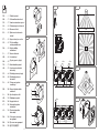 2
2
-
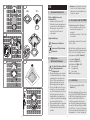 3
3
-
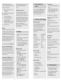 4
4
-
 5
5
-
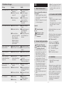 6
6
-
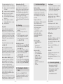 7
7
-
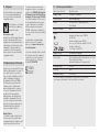 8
8
-
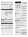 9
9
-
 10
10
-
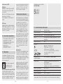 11
11
-
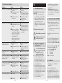 12
12
-
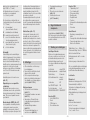 13
13
-
 14
14
-
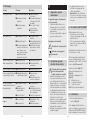 15
15
-
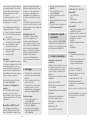 16
16
-
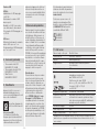 17
17
-
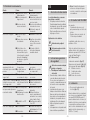 18
18
-
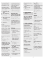 19
19
-
 20
20
-
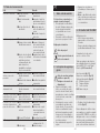 21
21
-
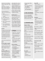 22
22
-
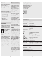 23
23
-
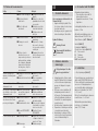 24
24
-
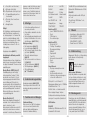 25
25
-
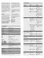 26
26
-
 27
27
-
 28
28
-
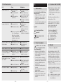 29
29
-
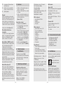 30
30
-
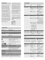 31
31
-
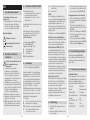 32
32
-
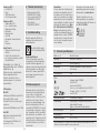 33
33
-
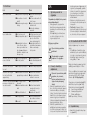 34
34
-
 35
35
-
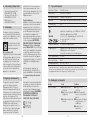 36
36
-
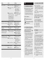 37
37
-
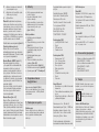 38
38
-
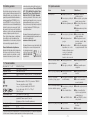 39
39
-
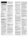 40
40
-
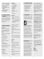 41
41
-
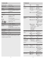 42
42
-
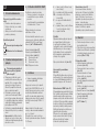 43
43
-
 44
44
-
 45
45
-
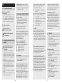 46
46
-
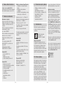 47
47
-
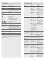 48
48
-
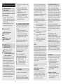 49
49
-
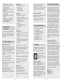 50
50
-
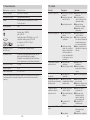 51
51
-
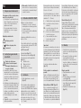 52
52
-
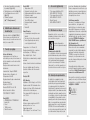 53
53
-
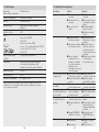 54
54
-
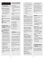 55
55
-
 56
56
-
 57
57
-
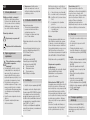 58
58
-
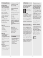 59
59
-
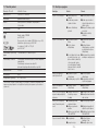 60
60
-
 61
61
-
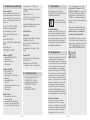 62
62
-
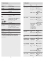 63
63
-
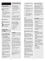 64
64
-
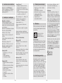 65
65
-
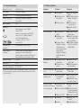 66
66
-
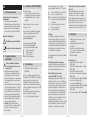 67
67
-
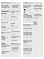 68
68
-
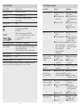 69
69
-
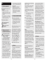 70
70
-
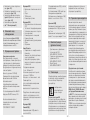 71
71
-
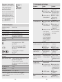 72
72
-
 73
73
-
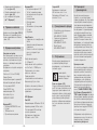 74
74
-
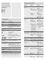 75
75
-
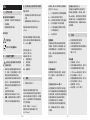 76
76
-
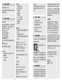 77
77
-
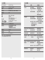 78
78


STEINEL IR Quattro SLIM XS 4m COM1 Manual de utilizare
- Tip
- Manual de utilizare
în alte limbi
Lucrări conexe
-
STEINEL IR Quattro MICRO 6m COM1 Manual de utilizare
-
-
-
-
-
-
-
-
-