
cover
Climbing Technology by Aludesign S.p.A. via Torchio 22
24034 Cisano B.sco BG ITALY www.climbingtechnology.com 1/43
Member of IST52-AXGRYCT_rev.1 03-23
AXESS QR
GRYPHON
MADE IN EUROPE
EN 361:2002
EN 358:2018
EN 813:2008
G
=+S
Regulation (EU) 2016/425
Personal Protective Equipment against falls from a height.
EN Adjustable work harnesses.
IT Imbracature da lavoro regolabili.
FR Harnais réglables pour le travaille.
DE Regulierbare Industriegurte.
ES Arneses ajustables de trabajo.
PL Regulowane szelki robocze.
PT Arneses de trabalho reguláveis.
SE Justerbara arbetsselar.
FI Säädettävät työvaljaat.
NO Regulerbare arbeidsseler.
DK Justerbar arbejds seler.
NL Harnasgordel.
SI Prilagodljivi delovni pasovi.
SK Nastaviteľné pracovné postroje.
RO Hamuri de lucru reglabile.
CZ Nastavitelné pracovní postroje.
HU Állítható mukahevederek.
GR Ρυθμιζόμενες πλεξούδες εργασίας.
EE Reguleeritavad töörakmed.
LV Regulējamas darba iekares.
LT Reguliuojami diržai.
BG Регулируеми работни сбруи.
HR Podesivi radni penjački pojasevi.
CN 可调工业安全。
8510
0333
0333

drawings
Climbing Technology by Aludesign S.p.A. via Torchio 22
24034 Cisano B.sco BG ITALY www.climbingtechnology.com 2/43
Member of IST52-AXGRYCT_rev.1 03-23
SIZE CHART
Model /
REF. No.
Axess QR /
7H164BCO1
Gryphon /
7H174BC
Axess QR /
7H164CDO1
Gryphon /
7H174CD
Axess QR /
7H164DEO1
Gryphon /
7H174DE
SIZE S-M M-L L-XL
A (cm) 160÷185 170÷190 180÷205
B (cm) 60÷80 70÷100 80÷120
C (cm) 45÷55 50÷60 55÷70
MAX RATED
LOAD 140 kg
A
B
C
A - Height of the user;
B - Circumference of the
belt; C - Circumference of
leg loops.
1
MAX
10 kg
0333
Serial No. AAAA
Made in Europe
ID
MM-YYYY
Aludesign S.p.A.
Via Torchio, 22
24034 Cisano B.Sco ITALY
BBBBBBBBB
AXESS QR
Ref. No. 7H164BCO1
S-M
A) 160÷185 cm
B) 60÷80 cm
C) 45÷55 cm
A
B
C
EN 361:2002
EN 358:2018
EN 813:2008
MAX RATED
LOAD 140 kg
EN 361
EN 358
DO NOT REMOVE THIS LABEL
Main materials: POLYESTER / POLYAMIDE
EN 813
EN 358
1
2
1
33 30
31 34 35
321211 T2T8
2 7 418
17 30
15 6
T9 T38
R
ONLY
FOR
HOOK
REST
ONLY FOR THE
CONNECTION
OF A WORK
SEAT
A
LABEL MARKING
2
GRYPHON
EN 358
R
A
A
AXESS
EN 358
R
A
P
S
N
M
B
P
E
C
DD
F F
OO R
H
HOO
RL
LLL
G
F
Q
I
F
Q
A
E
A
P
B
P
B
E
C
DD
F F
OO R
H
H
RL
L
G
S
N
M
Q
O
Q
I
T
O
LL
F
Q
A
F
Q
E
T
B
NOMENCLATURE OF PARTS
3.1 - Front side (Axess QR model) 3.2 - Back side (Axess QR model)
3.3 - Front side (Gryphon model) 3.4 - Back side (Gryphon model)
3
1
2
ADJUSTMENT
BUCKLES
4.1
4.2
4

Climbing Technology by Aludesign S.p.A. via Torchio 22
24034 Cisano B.sco BG ITALY www.climbingtechnology.com 3/43
Member of IST52-AXGRYCT_rev.1 03-23
A
A
A
A
A
A
AXESS QR - WEARING AND ADJUSTING THE HARNESS
5.1 - Axess QR 5.2 5.3
5.4 5.5 5.6
5.7 5.8
5
A
A
A
A
A
A
A
GRYPHON
EN 358
R
A
A
GRYPHON
EN 358
R
GRYPHON - WEARING AND ADJUSTING THE HARNESS
6.1 - Gryphon 6.2 6.3
6.4 6.5 6.6
6.7
6.8 6.9
6.10
6
A
A
A
A
A
A
A
GRYPHON
EN 358
R
A
A
GRYPHON
EN 358
R
GRYPHON - WEARING AND ADJUSTING THE HARNESS
6.1 - Gryphon 6.2 6.3
6.4 6.5
6.6 6.7
6.8 6.9 6.10
6
A
A
A
A
A
A
A
GRYPHON
EN 358
R
A
A
GRYPHON
EN 358
R
GRYPHON - WEARING AND ADJUSTING THE HARNESS
6.1 - Gryphon 6.2 6.3
6.4 6.5 6.6 6.7
6.8 6.9
6.10
6

Climbing Technology by Aludesign S.p.A. via Torchio 22
24034 Cisano B.sco BG ITALY www.climbingtechnology.com 4/43
Member of IST52-AXGRYCT_rev.1 03-23
AA
Made
Made
in
in
Italy
Italy
Patented
Patented
A
Made
Made
in
in
Italy
Italy
Patented
Patented
A
Made
Made
in
in
Italy
Italy
Patented
Patented
OK!
NO!
EN 362
A
7AXESS QR - ATTACHMENT OF THE CHEST ASCENDER
7.1 7.2 7.3
7.4 7.5
A
A
A
A
A
A
EN 362
Fixbar
NO!
OK!
GRYPHON - ATTACHMENT OF THE CHEST ASCENDER
8.1 8.2
8.3 8.4 8.5 8.6
8
A
A
A
A
A
A
EN 362
Fixbar
NO!
OK!
GRYPHON - ATTACHMENT OF THE CHEST ASCENDER
8.1 8.2
8.3 8.4 8.5 8.6
8

Climbing Technology by Aludesign S.p.A. via Torchio 22
24034 Cisano B.sco BG ITALY www.climbingtechnology.com 5/43
Member of IST52-AXGRYCT_rev.1 03-23
EN 361 EN 358 EN 358 EN 813
AR
EN 358 / EN 813
ATTACHMENT POINTS
9.1 - EN 361 - Fall arrest system 9.2 - EN 358
Work positioning 9.3 - EN 358
Work restraint 9.4 - Mod. AXESS QR
EN 813 Rope access 9.5 - Mod. GRYPHON: EN 358 Work
positioning / EN 813 Rope access
9
OK! NO!NO!
CORRECT POSITIONING OF THE HARNESS
10.1 10.2 10.3
10
ROPE ACCESS - EXAMPLES OF USE
11.1 11.2 11.3
11

Climbing Technology by Aludesign S.p.A. via Torchio 22
24034 Cisano B.sco BG ITALY www.climbingtechnology.com 6/43
Member of IST52-AXGRYCT_rev.1 03-23
Axess QR model Gryphon model
Axess QR model Gryphon model
MAX
10 kg
DANGER
WARNINGS
12.1 12.3 - Only for Hook Rest
12.2 - Only for the connection of a work seat 12.4
-4 ÷ +140°F
-20 ÷ +60°C
12
NO!
DANGER
A
AA
NO!
DANGER
NO!
DANGER
A
NO!
DANGER
EN 361 - WRONG
ATTACHMENT MODES
13.1
13.2 13.3 13.4
13
NO!
DANGER
A
AA
NO!
DANGER
NO!
DANGER
A
NO!
DANGER
EN 361 - WRONG
ATTACHMENT MODES
13.1
13.2 13.3 13.4
13

Climbing Technology by Aludesign S.p.A. via Torchio 22
24034 Cisano B.sco BG ITALY www.climbingtechnology.com 7/43
Member of IST52-AXGRYCT_rev.1 03-23
A
180°
HOOK REST - INSTALLATION
15.1 15.2
15
OK! NO!
DANGER
OK!
OK!
DANGER
14 USE WITH FALL ARREST LANYARD
14.1 14.2
14.3
OK! NO!
DANGER
OK!
OK!
DANGER
14 USE WITH FALL ARREST LANYARD
14.1 14.2
14.3

Climbing Technology by Aludesign S.p.A. via Torchio 22
24034 Cisano B.sco BG ITALY www.climbingtechnology.com 8/43
Member of IST52-AXGRYCT_rev.1 03-23
WORK SEAT - INSTRUCTIONS FOR
USE
17.1 - Axess QR
17.2 - Gryphon
17.3
17
A
A
A
A
NO!
DANGER
NO!
A
A
HOOK REST - INSTRUCTIONS FOR USE
16.1 - Connector fastening
16.3 - In case of fall
16.4
16.2 - Connector removing 16.5
16
WORK SEAT - INSTRUCTIONS FOR
USE
17.1 - Axess QR
17.2 - Gryphon
17.3
17

Climbing Technology by Aludesign S.p.A. via Torchio 22
24034 Cisano B.sco BG ITALY www.climbingtechnology.com 9/43
Member of IST52-AXGRYCT_rev.1 03-23
ENGLISH
The instruction manual for this device consists of general and specific instructions,
both must be carefully read and understood before use. Attention! This leaflet
shows the specific instruction only.
SPECIFIC INSTRUCTIONS EN 361 / 358 / 813.
This note contains the necessary information for a correct use of the following
product/s: Axess QR / Gryphon.
1) FIELD OF APPLICATION.
This product is a personal protective device (P.P.E.). It is compliant with the Regu-
lation (EU) 2016/425. EN 361:2002 - Full body harnesses against falls from a
height. EN 358:2018 - Belts for work positioning and restraint. EN 813:2008
- Sit harnesses. Attention! This product is intended to be integrated into fall pro-
tection systems, for example connectors and ropes. Attention! For this product
the indications of the standard EN 365 must be respected (general instructions
/ paragraph 2.5). Attention! For this product a periodic thorough inspection is
compulsory (general instructions / paragraph 8.)
1.1 - Intended uses.
The equipment is designed for the following applications: prevention of falls from
a height (EN 358 / EN 813); protection against falls from a height (EN 361).
2) NOTIFIED BODIES.
Refer to the legend in the general instructions (paragraph 9 / table D): M2; M6;
N1.
3) NOMENCLATURE (Fig. 3).
A) Label with marking. B) Adjustment buckle (mod. Axess QR) or quick-release
buckle (mod. Gryphon) of chest harness. C) Element for sternal attachment EN
361. D) Fastening straps for chest ascender. E) Capital letter A, denoting EN 361
attachment points. F) Element for side attachment EN 358. G) Ventral attachment
element EN 813 (mod. Axess QR) or EN 358 / EN 813 (mod. Gryphon). H)
Waistbelt adjustment buckles. I) The capital letter R, indicating the attachment ele-
ment EN 358, is intended for use only in work restraint. L) Leg loop quick-release
buckle with indicator for correct insertion and with a system that avoids accidental
sliding-through of the strap. M) Element for dorsal attachment EN 361. N) Adjust-
ment buckle rear chest harness. O) Waist belt gear loops. P) Support webbing for
Hook Rest. Q) Loops for tool-holder pouch. R) Loops used for the connection of a
work seat. T) Leg loop adjustment buckles.
3.1 - Main materials. Refer to the legend in the general instructions (paragraph
2.4): 1 / 3 (attachment points and buckles); 7 / 10 / 12 (webbings and seams).
4) MARKING.
Numbers/letters without caption: refer to the legend in the general instructions
(paragraph 5).
4.1 - General (Fig. 2). Indications: 1; 2; 4; 6; 7; 8; 11; 12; 15; 17; 18; 30)
Pictogram showing how to close and fix the adjustment buckles; 31) Pictogram
showing incorrect attachment point (Equipment-carrying loop). 32) Area to fill
in for the identification of the device; 33) Diagram showing the correct use of
attachment points. 34) Indication of webbing intended only for the insertion of the
Hook Rest support. 35) Caption indicating the loops intended for the connection
of a work-positioning seat.
4.2 - Traceability (Fig. 2). Indications: T2; T3; T8; T9.
5) CHECKS.
Further to the checks listed below, comply with what indicated in the general
instructions (paragraph 3). During each use: it is important to check regularly the
buckles and/or the adjustment devices.
6) SETTING.
Choose a harness of a suitable size, by consulting the chart (Fig. 1), containing
the following data: A) Height of the user; B) Circumference of the belt; C) Circum-
ference of leg loops.
6.1 - Putting the harness on. 1) Unfasten and extend the leg loops and (for
Gryphon model only) the chest harness using the corresponding quick-release
buckles. Extend the waist belt and the shoulder straps using their own adjustment
buckles (Fig. 5.1-6.1). 2) Move into the harness as shown (Fig. 5.2-6.2) and lift
the shoulder straps up until they rest on the shoulders (Fig. 5.3- 6.3). For Gryphon
model only, fasten the quick-release buckle of the left shoulder strap (Fig. 6.4).
6.2 - Fastening and adjustment. 1) Adjust the waist belt using the adjustment
buckles (Fig. 5.4-6.5) in order to make it fit perfectly to the body without being
too tight. Pass any excess strap through the appropriate retainers. 2) Fasten the leg
loops (Fig. 5.5-6.6) and adjust them using the quick-release buckles (Fig. 5.6-6.7)
to the point that there is space enough to insert a hand between the leg loop and
the leg. Pass any excess strap through the appropriate retainers. 3) By using the
adjustment buckle N, adjust the distance between chest harness and waist belt
in order to place the attachment point to the correct height (Fig. 5.7-6.8). 4) For
Gryphon model only, adjust the rear webbing of the leg loops using the dedicated
buckles (Fig. 6.9), so that they are not excessively slack. This adjustment is espe-
cially important when using the EN 361 rear attachment point. 5) Finally, adjust
the chest harness using the adjustment buckles (Fig. 5.8-6.10). Pass any excess
strap through the appropriate retainers. Attention! Before use, perform a test for
fitting and adjustability in a safe place, in order to make sure that the harness is
of the correct size, it enables adequate adjustment and it has an acceptable level
of comfort for its intended use.
6.3 - Ventral rope clamp. The harness is equipped with two fastening straps de-
signed for the attachment of a chest ascender. To install the ventral rope clamp, a
triangular quick-link (EN 362) has to be used and, if present, a positioning support
FIXBAR, following the instructions in Figure (Fig. 7-8). The positioning support Fix-
bar, if present, is used to hold the triangular quick link in place and the drawings
show the correct way to mount it (Fig. 8.1÷8.3). Attention! The Fixbar is not a PPE
and is not designed to support the weight of the user. Attention! An error can have
extremely serious consequences, any other way of mounting and use is forbidden.
6.4 - Work positioning seat. The harness is provided with two loops for the
fastening of a work positioning seat (Fig. 17.1-17.2). This solution increases the
comfort during use and leaves free the ventral attachment point for other manoeu-
vres. Alternatively, it is anyway possible to attach the work positioning seat to the
ventral attachment point (Fig. 17.3).
7) ISTRUCTIONS FOR USE.
Any activity carried out at height requires the use of Personal Protection Equipment
(PPE) as a protection against the risk of a fall. Before accessing the work station,
all the risk factors must be evaluated (environmental, concomitant, consequential).
7.1 - EN 361:2002. The device complies with EN 361 standard and the tests
were carried out and passed using a 140 kg dummy. Attention! In case of use
by users weighing more than 100 kg (equipment included) always check the
compatibility of the energy absorbers used in terms of declared load. The sternal
and dorsal attachment elements are marked with the letter A and are intended for
the connection to a fall arrest equipment covered by EN 363 (for example: energy
absorber, guided type fall arrester, etc). A full body harness against falls from a
height is a component of a fall arrest system, and it must be used in combination
with anchorages EN 795, shock absorbers EN 355, connectors EN 362 etc.
Attention! To connect to a reliable anchor point or to a connection subsystem,
only use EN 362 connectors. Attention! Please check the value of the clearance
distance of the fall arrest device used in the instruction manual. Attention! Only
anchor points that comply with the EN 795 standard can be used (minimum
strength 12 kN or 18 kN for non-metallic anchors) that do not have sharp edges.
Attention! The user must always be positioned below the anchor point.
7.2 - EN 358:2018. The belt is approved for use by a user of 140 kg, tools and
equipment included. The lateral attachment elements are intended for the user’s
positioning at the work station and must be used to connect a work-positioning
lanyard. The ventral attachment element, certified to EN 358 or EN 358 / EN
813, can also be used to connect a work-positioning or restraint lanyard. Make
sure it is possible to rest the feet to work in a comfortable way. Adjust the posi-
tioning lanyard in such a way that it is in tension; that the anchor point is at a
height equal to or greater than the height of the waist belt. Attention! Attachment
elements EN 358 are not suitable to arrest a fall. A work positioning belt should
not be used where the foreseeable risk of the user being suspended from the belt
or exposed to an involuntary tension through the belt itself exists. Attention! Using
a work positioning system, the user is normally supported by the equipment. As
a consequence, it is essential to consider using a backup system such as a fall
protection system. Attention! The two lateral attachment elements must always
be used together, by linking them with a positioning lanyard. Attention! The rear
attachment point, identified by the letter R, is intended for use in a restraint system
and thus it can only be used to prevent the user from entering an area where a
fall is possible.
7.3 - EN 813:2008. Maximum rated load: 140 kg. The ventral attachment ele-
ment is intended for use in work positioning and restraint systems and rope access
systems. It can be used to connect a positioning lanyard, a restraint lanyard, a
descender, etc. Attention! The attachment element EN 813 is not suitable to arrest
a fall. Attention! The user must always be positioned below the anchor point.
7.4 - Additional warnings. 1) Gear loops are to be used only to hang materials.
Do not use for other purposes (fastening, abseiling etc.). Attention! The horizontal
webbing located on the shoulders are designed exclusively to insert the Hook Rest
support (Ref. No. 6V522) and should not be used for other purposes (Fig. 13.1).
The Hook Rest support is exclusively designed for the positioning of a fall arrester
lanyard while not in use. (Fig. 14.1-16). It is designed to release the connector
if subjected to a load exceeding a few kilograms, so that it does not interfere
with the opening of the energy absorber in the event of a fall (Fig. 16.3). 2) Inert
suspension in the harness can cause serious physiological injuries and, in extreme
cases, fatality. Attention! Take all the necessary precautions to minimize the likeli-
hood of an inert suspension and its duration.
8) SYMBOLS.
Refer to the legend in the general instructions (paragraph 16): F1.

Climbing Technology by Aludesign S.p.A. via Torchio 22
24034 Cisano B.sco BG ITALY www.climbingtechnology.com 10/43
Member of IST52-AXGRYCT_rev.1 03-23
ITALIANO
Le istruzioni d’uso di questo dispositivo sono costituite da un’istruzione generale e
da una specifica ed entrambe devono essere lette attentamente prima dell’utiliz-
zo. Attenzione! Questo foglio costituisce solo l’istruzione specifica.
ISTRUZIONI SPECIFICHE EN 361 / 358 / 813.
Questa nota contiene le informazioni necessarie per un utilizzo corretto del se-
guente prodotto/i: Axess QR / Gryphon.
1) CAMPO DI APPLICAZIONE.
Questo prodotto è un dispositivo di protezione individuale (D.P.I.). Esso è confor-
me al regolamento (UE) 2016/425. EN 361:2002 - Imbracature anticaduta
per il corpo. EN 358:2018 - Cinture di posizionamento sul lavoro e trattenuta.
EN 813:2008 - Imbracature basse. Attenzione! Questo prodotto è destinato ad
essere integrato in sistemi di protezione contro le cadute, per esempio connettori
e funi. Attenzione! Per questo prodotto devono essere rispettate le indicazioni
della norma EN 365 (istruzioni generali / paragrafo 2.5). Attenzione! Per questo
prodotto è obbligatorio un controllo periodico approfondito (istruzioni generali /
paragrafo 8).
1.1 - Destinazioni d’uso.
Il dispositivo è progettato per i seguenti scopi: prevenzione contro le cadute
dall’alto (EN 358 / EN 813); protezione contro le cadute dall’alto (EN 361).
2) ORGANISMI NOTIFICATI.
Consultare la legenda nelle istruzioni generali (paragrafo 9 / tabella D): M2;
M6; N1.
3) NOMENCLATURA (Fig. 3).
A) Etichetta con marcatura. B) Fibbia di regolazione (mod. Axess QR) o a sgancio
rapido (mod. Gryphon) del pettorale anteriore. C) Elemento di attacco sternale
EN 361. D) Fettucce di fissaggio per bloccante ventrale. E) Lettera maiuscola
A, indicante gli elementi di attacco EN 361. F) Elemento di attacco laterale EN
358. G) Elemento di attacco ventrale EN 813 (mod. Axess QR) o EN 358 / EN
813 (mod. Gryphon). H) Fibbie di regolazione cintura. I) Lettera maiuscola R, in-
dicante l’elemento di attacco EN 358 destinato al solo utilizzo in trattenuta. L) Fib-
bia a sgancio rapido cosciali con indicatore di corretto inserimento e sistema che
evita lo scorrimento accidentale della fettuccia. M) Elemento di attacco dorsale
EN 361. N) Fibbia di regolazione pettorale posteriore. O) Asole porta-materiali
cintura. P) Fettuccia per supporto Hook Rest. Q) Asole per custodia porta attrezzi.
R) Asole destinate al collegamento di un sedile di posizionamento. S) Rivestimento
posteriore pettorale. T) Fibbie di regolazione posteriore dei cosciali.
3.1 - Materiali principali. Consultare la legenda nelle istruzioni generali (paragra-
fo 2.4): 1 / 3 (elementi di attacco e fibbie); 7 / 10 / 12 (fettucce e cuciture).
4) MARCATURA.
Numeri/lettere senza didascalia: consultare la legenda nelle istruzioni generali
(paragrafo 5).
4.1 - Generale (Fig. 2). Indicazioni: 1; 2; 4; 6; 7; 8; 11; 12; 15; 17; 18; 30)
Pittogramma che illustra come chiudere e fissare le fibbie di chiusura e regola-
zione; 31) Pittogramma che illustra un errato punto di aggancio (asola porta-ma-
teriali); 32) Area compilabile per identificazione dispositivo; 33) Pittogramma
che illustra i punti corretti di aggancio. 34) Indicazione delle fettucce destinate
unicamente all’inserimento del supporto Hook Rest. 35) Indicazione delle asole
destinate al collegamento di un sedile di posizionamento.
4.2 - Tracciabilità (Fig. 2). Indicazioni: T2; T3; T8; T9.
5) CONTROLLI.
Oltre ai controlli indicati di seguito rispettare quanto indicato nelle istruzioni ge-
nerali (paragrafo 3). Durante ogni utilizzo: è importante controllare regolarmente
fibbie e/o dispositivi di regolazione.
6) REGOLAZIONE.
Scegliere un’imbracatura di taglia adeguata consultando l’apposita tabella (Fig.
1), contenente i valori di: A) Statura dell’utilizzatore; B) Circonferenza della cintu-
ra; C) Circonferenza dei cosciali.
6.1 - Indossaggio. 1) Aprire ed allargare i cosciali e, solo nel modello Gryphon,
il pettorale mediante le relative fibbie a sgancio rapido. Allargare la cintura e
gli spallacci agendo sulle relative fibbie di regolazione (Fig. 5.1-6.1). 2) Entrare
nell’imbracatura come mostrato (Fig. 5.2-6.2) e sollevare gli spallacci fino a farli
appoggiare sulle spalle (Fig. 5.3- 6.3). Per il solo modello Gryphon chiudere la
fibbia a sgancio rapido posta sullo spallaccio sinistro (Fig. 6.4).
6.2 - Chiusura e regolazione. 1) Regolare la cintura per mezzo delle fibbie di
regolazione (Fig. 5.4-6.5) in modo che aderisca perfettamente al corpo, sen-
za risultare troppo stretta. Inserire l’eventuale fettuccia in eccesso negli appositi
passanti. 2) Chiudere i cosciali (Fig. 5.5-6.6) e regolarli per mezzo delle fibbie
a sgancio rapido (Fig. 5.6-6.7) in modo che una mano possa passare fra il
cosciale e la gamba dell’utilizzatore. Inserire l’eventuale fettuccia in eccesso negli
appositi passanti. 3) Agire sulla fibbia di regolazione N in modo da regolare la
distanza pettorale/cintura consentendo al punto di attacco di posizionarsi all’al-
tezza corretta (Fig. 5.7-6.8). 4) Per il solo modello Gryphon regolare le fettucce
posteriori dei cosciali, mediante le relative fibbie (Fig. 6.9), in modo che non
siano eccessivamente lasche. Questa regolazione è importante soprattutto in caso
di utilizzo del punto di attacco posteriore EN 361. 5) Regolare infine il pettorale
agendo sulle fibbie di regolazione (Fig. 5.8-6.10). Inserire l’eventuale fettuccia
in eccesso negli appositi passanti. Attenzione! Prima dell’utilizzo è necessario
effettuare una prova di sospensione in un luogo sicuro, per assicurarsi che l’imbra-
catura sia della misura giusta, abbia possibilità di regolazione sufficiente e sia di
un livello di comodità accettabile per l’utilizzo a cui è destinata.
6.3 - Bloccante ventrale. L’imbracatura è dotata di due fettucce per il fissaggio
di un bloccante ventrale. Per l’installazione del bloccante ventrale utilizzare una
maglia rapida triangolare (EN 362) e, laddove presente, un supporto di posizio-
namento Fixbar, attenendosi a quanto mostrato (Fig. 7-8). Il supporto di posizio-
namento Fixbar, laddove presente, serve a mantenere correttamente in posizione
la maglia rapida triangolare e nei disegni ne è indicata la corretta modalità di
montaggio (Fig. 8.1÷8.3). Attenzione! Il supporto Fixbar non è un DPI e non è
progettato per sostenere il peso dell’utilizzatore. Attenzione! Un errore può avere
conseguenze estremamente gravi, qualsiasi modalità di montaggio e utilizzo di-
versa da quanto indicato è da considerarsi vietata.
6.4 - Sedile di posizionamento. L’imbracatura è provvista di due asole dedicate
al collegamento di un sedile di posizionamento (Fig. 17.1-17.2). Questa soluz-
ione migliora il comfort durante l’utilizzo e lascia libero l’anello ventrale per altre
manovre. In alternativa è possibile comunque collegare il sedile di posizionamen-
to all’anello ventrale (Fig. 17.3).
7) ISTRUZIONI D’USO.
Qualsiasi lavoro in quota presuppone l’impiego di Dispositivi di Protezione In-
dividuale (DPI) contro il rischio di cadute. Prima di accedere alla postazione di
lavoro si devono considerare tutti i fattori di rischio (ambientali, concomitanti,
consequenziali).
7.1 - EN 361:2002. Il dispositivo è conforme alla EN 361 e le prove sono state
condotte e superate con un manichino di 140 kg. Attenzione! In caso di utilizzo
da parte di utenti di peso superiore a 100 kg (attrezzatura inclusa) verificare sem-
pre la compatibilità, in termini di carico dichiarato, degli assorbitori di energia
impiegati. Gli elementi di attacco sternale e dorsale sono segnalati dalla lettera
A e sono destinati a connettere un dispositivo di arresto caduta contemplato dalla
EN 363 (es. assorbitore di energia, anticaduta guidato su corda etc.). Un’imbra-
catura anticaduta per il corpo è un componente di un sistema di arresto caduta e
può essere impiegata in combinazione con ancoraggi EN 795, assorbitori EN
355, connettori EN 362 etc. Attenzione! Per effettuare il collegamento ad un
punto di ancoraggio affidabile o ad un sottosistema di collegamento utilizzare
esclusivamente connettori EN 362. Attenzione! Verificare il valore del tirante d’a-
ria del dispositivo anticaduta impiegato nelle relative istruzioni d’uso. Attenzione!
Si devono utilizzare esclusivamente punti di ancoraggio, conformi alla norma EN
795 (resistenza minima 12 kN o 18 kN per ancoraggi non metallici), che non
presentino spigoli taglienti. Attenzione! L’utilizzatore dovrà trovarsi sempre al di
sotto del punto di ancoraggio.
7.2 - EN 358:2018. La cintura è approvata per l’impiego da parte di un utilizza-
tore, compresi strumenti e attrezzature, di 140 kg. Gli elementi di attacco laterali
sono destinati al posizionamento dell’utilizzatore sul luogo di lavoro e devono
essere utilizzati per collegare un cordino di posizionamento sul lavoro. Anche l’e-
lemento di attacco ventrale, certificato EN 358 o EN 358 / EN 813, può essere
utilizzato per collegare un cordino di posizionamento o di trattenuta. Accertarsi di
potere appoggiare i piedi per lavorare confortevolmente. Regolare il cordino di
posizionamento in modo che risulti in tensione e che il punto di ancoraggio si trovi
ad un’altezza uguale o superiore a quella della cintura. Attenzione! Gli elementi
di attacco EN 358 non sono adatti ad arrestare una caduta. Una cintura di trat-
tenuta non dovrebbe essere utilizzata laddove sia prevedibile il rischio che l’utiliz-
zatore rimanga sospeso alla cintura o venga esposto ad una tensione involontaria
tramite la cintura stessa. Attenzione! Utilizzando un sistema di posizionamento
sul lavoro, l’utilizzatore normalmente è sostenuto dall’equipaggiamento. Di conse-
guenza è essenziale considerare l’utilizzo di un sistema di backup, ad esempio un
sistema anticaduta. Attenzione! I due elementi di attacco laterali vanno utilizzati
sempre insieme, collegandoli mediante un cordino di posizionamento. Attenzio-
ne! Il punto di attacco posteriore, identificato dalla lettera R, è destinato all’utilizzo
in trattenuta e serve quindi unicamente ad impedire all’utilizzatore di raggiungere
un luogo da dove una caduta sia possibile.
7.3 - EN 813:2008. Carico nominale massimo: 140 kg. L’elemento di attacco
ventrale è destinato all’uso in sistemi di trattenuta, di posizionamento sul lavoro e
di accesso con fune. Esso può essere utilizzato per collegare un cordino di posi-
zionamento o di trattenuta, un discensore etc. Attenzione! L’elemento di attacco
EN 813 non è adatto ad arrestare una caduta. Attenzione! L’utilizzatore dovrà
trovarsi sempre al di sotto del punto di ancoraggio.
7.4 - Avvertenze supplementari. 1) Le asole porta-materiali servono solo ad ap-
pendere materiali. Non usare per altri scopi (assicurarsi, calarsi etc.). Attenzione!
Le fettucce orizzontali situate sulle bretelle sono progettate esclusivamente per
inserire il supporto Hook Rest (Ref. No. 6V522) e non devono essere utilizzate
per altri scopi (Fig. 13.1). Il supporto Hook Rest è destinato esclusivamente al
posizionamento dei moschettoni di un cordino anticaduta quando non utilizzato
(Fig. 14.1-16). Esso è progettato per rilasciare il connettore se sottoposto a un ca-
rico superiore a qualche chilogrammo, in modo da non interferire con l’apertura

Climbing Technology by Aludesign S.p.A. via Torchio 22
24034 Cisano B.sco BG ITALY www.climbingtechnology.com 11/43
Member of IST52-AXGRYCT_rev.1 03-23
dell’assorbitore di energia in caso di caduta (Fig. 16.3). 2) La sospensione inerte
nell’imbracatura può provocare gravi disturbi fisiologici o la morte. Attenzione!
Adottare tutte le precauzioni necessarie al fine di ridurre al minimo la probabilità
di una sospensione inerte e la relativa durata.
8) SIMBOLI.
Consultare la legenda nelle istruzioni generali (paragrafo 16): F1.

Climbing Technology by Aludesign S.p.A. via Torchio 22
24034 Cisano B.sco BG ITALY www.climbingtechnology.com 12/43
Member of IST52-AXGRYCT_rev.1 03-23
FRANÇAIS
Les instructions d’utilisation de ce dispositif comprennent une partie générale et
une partie spécifique, lesquelles doivent toutes les deux être lues attentivement
avant utilisation. Attention ! La présente fiche ne contient que les instructions spé-
cifiques.
INSTRUCTIONS SPÉCIFIQUES EN 361 / 358 / 813.
Cette note contient les informations nécessaires à l’utilisation correcte du produit/s
suivant/s : Axess QR / Gryphon.
1) CHAMP D’APPLICATION.
Ce produit est un dispositif de protection individuelle (E.P.I.). Il est conforme au
Règlement (UE) 2016/425. EN 361:2002 - Harnais antichute pour le corps.
EN 358:2018 - Ceintures de maintien au travail et de retenue. EN 813:2008
- Harnais cuissard. Attention ! Ce produit est destiné à être intégré dans des sys-
tèmes de protection contre les chutes, par exemple des connecteurs et des cordes.
Attention ! Pour ce produit il faut respecter les indications de la norme EN 365
(Instructions générales / paragraphe 2.5). Attention ! Pour ce produit un contrôle
approfondi est obligatoire (Instructions générales / paragraphe 8).
1.1 - Destination.
Le dispositif à été réalisé pour la prévention des chutes en hauteur (EN 358 / EN
813) ; protection contre les chutes en hauteur (EN 361).
2) ORGANISMES NOTIFIÉS.
Consulter la légende dans les instructions générales (paragraphe 9/tableau D) :
M2 ; M6 ; N1.
3) NOMENCLATURE (Fig. 3).
A) Étiquette portant un marquage. B) Boucle de régulation (modalité Axess QR)
ou à décrochage rapide (modèle Gryphon) du harnais torse antérieur. C) Point
d’attache sternal EN 361. D) Sangles de fixation pour bloquer ventral. E) Lettre
majuscule A, indiquant les points d’attache sternal EN 361. F) Point d’attache
latéral EN 358. G) Élément d‘attache ventral EN 813 (modèle Axess QR) ou EN
358 / EN 813 (modèle Gryphon). H) Boucles de régulation ceinture. I) Lettre
majuscule R, indiquant le point d’attache EN 358 destiné à être utilisé uniquement
en retenue. L) Boucle à décrochage rapide sur les tours de cuisse avec témoin
indiquant que la sangle est correctement attachée et système évitant le coulisse-
ment accidentel de la sangle. M) Point d’attache dorsal EN 361. N) Boucle de
réglage pectorale postérieure. O) Anneaux porte-matériel ceinture. P) Sangle pour
support Hook Rest. Q) Anneaux pour pochette porte-outils. R) Boucles destinées
à la connexion d’un siège de positionnement. S) Revêtement postérieur torse. T)
Boucles de régulation postérieures des tours de cuisse.
3.1 - Matériaux principaux. Consulter la légende dans les instructions générales
(paragraphe 2.4): 1 / 3 (points d’attache et boucles) ; 7 / 10 / 12 (sangles
et coutures).
4) MARQUAGE.
Chiffres/lettres sans légende : consulter la légende dans les instructions générales
(paragraphe 5).
4.1 - Général (Fig. 2). Indications : 1 ; 2 ; 4 ; 6 ; 7 ; 8 ; 11 ; 12 ; 15 ; 17 ; 18
; 30) Pictogramme illustrant la procédure de fermeture et de fixation des boucles
de réglage ; 31) Pictogramme indiquant un point d’attache incorrect (anneau
porte-matériel) ; 32) Surface compilable pour l’identification du dispositif ; 33) Pic-
togramme indiquant les points corrects d’attache. 34) Indication des sangles des-
tinées uniquement à l’insertion du support Hook Rest. 35) Indication des boucles
destinées à être rattachés à un siège de positionnement.
4.2 - Traçabilité (Fig. 2). Indications : T2; T3; T8; T9.
5) CONTROLES.
En plus des contrôles indiqués en suite, il faut respecter ce qui est indiqué dans les
instructions générales (paragraphe 3). Pendant chaque utilisation: il est important
de contrôler régulièrement les boucles et/ou matériaux de réglage.
6) RÉGLAGE.
Choisir un harnais d’une taille appropriée à l’aide du tableau prévu à cet effet
(Fig. 1), contenant les valeurs relatives aux aspects suivants : A) Stature de l’utilisa-
teur ; B) circonférence de la ceinture ; C) Circonférence des cuissards.
6.1 - Enfilage. 1) Ouvrir et élargir les tours de cuisse et, seulement pour le modèle
Gryphon, le harnais torse par le biais de ses boucles à décrochage rapide.
Élargir la ceinture et les bretelles en faisant coulisser la sangle dans les boucles
de réglages prévues à cet effet (Fig. 5.1-6.1). 2) Enfiler le harnais comme illustré
(Fig. 5.2-6.2) et remonter les bretelles jusqu’à ce qu’elles prennent place sur les
épaules (Fig. 5.3- 6.3). Seulement pour le modèle Gryphon fermer la boucle à
décrochage rapide situé sur l‘épaulière (Fig. 6.4).
6.2 - Fermeture et réglage. 1) Régler la ceinture grâce aux boucles de réglage
(Fig. 5.4-6.5) de manière qu’elle épouse parfaitement le corps, sans être trop
serrée. Faire passer la sangle en trop dans les passants prévus à cet effet. 2)
Accrocher les tours de cuisse (Fig. 5.5-6.6) et les régler grâce aux boucles à
décrochage rapide (Fig. 5.6-6.7) de manière qu’une main puisse passer entre
le tour de cuisse et la jambe de l’utilisateur. Faire passer la sangle en trop dans
les passants prévus à cet effet. 3) Faire coulisser la boucle de réglage N pour
régler la distance torse/ceinture de manière à permettre au point d’attache d’être
placé à la bonne hauteur (Fig. 5.7-6.8). 4) Seulement pour le modèle Gryphon
régler les sangles postérieures des tours de cuisse, par le biais de leur sangles
(Fig. 6.9) de façon qu‘elles ne soient pas trop larges. Ce réglage est important
surtout en cas d‘utilisation du point d‘attache postérieur EN 36. 5) Enfin, régler
le torse grâce aux boucles de réglage (Fig. 5.8-6.10). Faire passer la sangle
en trop dans les passants prévus à cet effet. Attention ! Avant d’utiliser pour la
première fois le matériel, essayer le matériel dans un lieu sûr pour savoir s’il est
facile à porter et à régler et pour s’assurer que le harnais est de taille appropriée,
qu’il permet un réglage suffisant et présente un niveau de confort acceptable pour
l’utilisation prévue.
6.3 - Bloquer ventral. Le harnais est équipé avec deux sangles pour la fixation
d’un bloquer ventral. Pour installer le bloquer ventral utiliser un maillon rapide trian-
gulaire (EN 362) et, si présent, un support de positionnement Fixbar, en suivant
les indications (Fig. 7-8). Le support de positionnement Fixbar, s’il est présent, sert
à maintenir le maillon rapide triangulaire correctement en position et les dessins
indiquent la méthode de montage correcte (Fig. 8.1÷8.3). Attention ! Le support
Fixbar n’est pas un EPI et n’est pas conçu pour supporter le poids de l’utilisateur.
Attention ! Une erreur peut avoir des conséquences extrêmement graves ; toute
méthode de montage et d’utilisation autre que celle indiquée est interdite.
6.4 - Sellette de positionnement. Le harnais est doté de deux anneaux pour
l’attachement d’une sellette de positionnement (Fig. 17.1-17.2). Cette solution
améliore le confort pendant l’utilisation et laisse libre l’anneau ventral pour autres
manouvres. Alternativement, il est en tout cas possible d’attacher la sellette de
positionnement à l’anneau ventral (Fig. 17.3).
7) INSTRUCTIONS D’UTILISATION.
Pour tout travail en hauteur il est obligatoire d’utiliser des Équipements de Protec-
tion Individuelle (EPI) contre le risque de chutes. Avant d’accéder à la position de
travail, il est fondamental de prendre en considération tous les facteurs de risques
(environnementaux, concomitants, consécutifs).
7.1 - EN 361:2002. Le dispositif est conforme à la Norme EN 361 et les essais
ont étés réalisées et réussites avec un mannequin de 140 kg. Attention ! En cas
d’utilisation de la part d’utilisateurs ayant un poids supérieur à 100 kg (équipe-
ment inclus) toujours vérifier la compatibilité, en terme de charge déclarée, des
absorbeurs d’énergie employés. Les éléments d‘attache sternal et dorsal sont indi-
qués par la lettre A et sont destinés à la connexion d‘un dispositif d‘arrêt de chute
prévu par la EN 363 (ex : absorbeur d’énergie, antichute guidé sur cordes etc.).
Un harnais antichute pour le corps est un composant d’un système d’arrêt antichute
et peut être utilisé en combinaison avec d’autres amarrages EN 795, absorbeurs
EN 355, connecteurs EN 362, etc. Attention ! Pour effectuer la connexion à un
point d’ancrage fiable ou à un sous-système de connexion utiliser exclusivement
les connecteurs EN 362. Attention ! Contrôler la valeur du tirant d’air du dispositif
antichute utilisée dans les instructions d’utilisation. Attention ! S’il faut utiliser seule-
ment des points d’amarrage conformes à la norme EN 795 (résistance minimale
12 kN ou 18 kN pour amarrages non métalliques) et ne présentant pas de bords
tranchants. Attention ! L’utilisateur devra toujours se trouver au-dessous du point
d’ancrage.
7.2 - EN 358:2018. La ceinture est approuvée pour être utilisée par un utilisateur,
en comprenant les outils et l’équipement, de 140 kg. Les éléments d‘attache sur
les cotés sont destinés au positionnement de l‘utilisateur sur le lieu de travail et
doivent être utilisés pour connecter une cordelette de positionnement sur le travail.
L‘élément d‘attache ventral, certifié EN 358 ou EN 358/ EN 813 peut être utilisé
pour connecter une cordelette de positionnent ou de retenue. S’assurer d’être ne
mesure de poser les pieds afin de pouvoir travailler dans les meilleures conditions.
Régler la longe de maintien au travail de manière à la mettre en tension et en
veillant à ce que le point d’ancrage se trouve à une hauteur égale ou supérieure
à celle de la ceinture. Attention ! Les points d’attache EN 358 ont été conçus
pour arrêter une chute. Il ne faut pas utiliser une ceinture de retenue si on prévoit le
risque que l’utilisateur reste en suspension sur la ceinture ou soit soumis à une ten-
sion involontaire au moyen de la même ceinture. Attention ! Dans le cas d’emploi
d’un système de positionnement sur le lieu de travail, l’utilisateur normalement est
soutenu par l’équipement. Pourtant, il est essentiel de considérer l’emploi d’un sys-
tème de soutien, par exemple un système antichute. Attention! Les deux éléments
d’attache latéraux doivent toujours être utilisés ensemble, en les reliant grâce à une
longe de maintien au travail. Attention! Le point d’attache dorsal, identifié par la
lettre R, est destiné à être utilisé en retenue et sert donc uniquement à empêcher
l’utilisateur d’atteindre une zone où une chute est possible.
7.3 - EN 813:2008. Charge nominale maximale : 140 kg. L’élément d’attache
ventral est destiné à une utilisation dans les systèmes de retenue, de positionne-
ment sur le travail et d’accès avec câble. Il peut être utilisé pour connecter une cor-
delette de positionnement ou de retenue, un descendeur etc. Attention ! Le point
d’attache EN 813 n’est pas adapté pour arrêter une chute. Attention ! L’utilisateur
devra toujours se trouver au-dessous du point d’ancrage.
7.4 - Autres avertissements. 1) Les anneaux porte-matériel servent à pendre le
matériel. Ne jamais les utiliser à d’autres fins (assurage, descente etc.). Attention
! Les sangles horizontales situées sur les bretelles ont été réalisées exclusivement
pour insérer le support Hook Rest (Ref. No. 6V522) et ne doivent pas être utilisées
pour d’autres fins (Fig. 13.1). Le support HOOK REST est conçu uniquement pour

Climbing Technology by Aludesign S.p.A. via Torchio 22
24034 Cisano B.sco BG ITALY www.climbingtechnology.com 13/43
Member of IST52-AXGRYCT_rev.1 03-23
le placement des mousquetons d’une longe antichute, quand il n’est pas utilisé.
(Fig. 14.1-16). Il a été projeté pour pour libérer le connecteur si soumis à une
charge supérieure à quelques kilogrammes, de manière à ne pas interférer avec
le fonctionnement de l’absorbeur d’énergie en cas de chute (Fig. 16.3). 2) La
suspension inerte dans le harnais risque de provoquer de graves dommages
physiologiques, voire de conduire à la mort. Attention ! Adopter toutes les pré-
cautions nécessaires afin de réduire au minimum les probabilités de suspension
inerte et relative durée.
8) SYMBOLES.
Consulter la légende dans les instructions générales (paragraphe 16) : F1.

Climbing Technology by Aludesign S.p.A. via Torchio 22
24034 Cisano B.sco BG ITALY www.climbingtechnology.com 14/43
Member of IST52-AXGRYCT_rev.1 03-23
DEUTSCH
Die Gebrauchsanweisung zu diesem Produkt setzt sich aus einem allgemeinen
und einem spezifischen Teil zusammen, wobei beide Teile vor der Verwendung
des Produkts genau durchgelesen werden müssen. Achtung! Dieses Blatt enthält
nur den allgemeinen Teil der Anleitung.
SPEZIFISCHE ANWEISUNGEN EN 361 / 358 / 813.
Diese Anmerkung enthalt die notwendige Informationen für einen korrekten Ge-
brauch des folgenden Produktes/e: Axess QR / Gryphon.
1) ANWENDUNGSBEREICH.
Dieses Produkt ist eine Persönliche Schutzausrüstung (P.S.A.). Entspricht der EU-Re-
gelung 2016/425. EN 361:2002 - Auffanggurte EN 358:2018 - Gurte zur Ar-
beitsplatzpositionierung und Haltegurte EN 813:2008. Achtung! Dieses Produkt
ist zur Integration in Absturzsicherungssysteme vorgesehen, z. B. Karabiner und
Seile. Achtung! Für dieses Produkt muss die Anleitung der Norm EN 365 beach-
ten werden (allgemeine Gebrauchsanweisungen / Absatz 2.5). Achtung! Für
dieses Produkt ist eine gründliche regelmäßige Kontrolle verpflichtet (allgemeine
Gebrauchsanweisungen / Absatz 8).
1.1 - Anwendungsbereich.
Das Gerät wurde für folgende Ziele entworfen: Verhinderung von Abstürzen (EN
358 / EN 813); Schutz vor Abstürzen (EN 361).
2) BENANNTEN STELLEN.
Die Legende in der allgemeine Gebrauchsanweisungen lesen (Absatz 9 / Tabelle
D): M2; M6; N1.
3) NOMENKLATUR (Abb. 3).
A) Etikett mit Kennzeichnung. B) Einstellschnalle (Mod. Axess QR) oder mit
Schnellöffnungsfunktion (Mod. Gryphon) des vorderen Brustgurts. C) Auffangöse
auf Brusthöhe EN 361. D) Befestigungsriemen für Bruststeigklemme. E) Großbuch-
stabe A, steht für die Einbindungselemente EN 361. F) Seitliche Auffangöse EN
358. G) Ventraler Anschlagpunkt EN 813 (Mod. Axess QR) oder EN 358 / EN
813 (Mod. Gryphon). H) Einstellschnallen des Gurts. I) Großbuchstabe R, welcher
das Anschlagmittel EN 358 angibt, dass nur für Rückhaltesystem dient. L) Schnell
lösbare Schnalle an Beinschlaufen mit Indikator für korrektes Einfügen und System,
welches unvorhergesehenes Verrutschen der Schlinge vermeidet. M) Rückseitige
Auffangöse EN 361. N) Hintere Brustschnalle zum Einstellen. O) Materialträgerö-
sen am Gurt. P) Bandschlinge für Hook Rest. Q) Ösen für Materialbeutel. R) Ösen,
die zum Befestigen einer Sitzfläche für Positionierungen bestimmt sind. S) Hintere
Beschichtung des Brustgurts. T) Einstellschnallen hinten an den Beinschlaufen.
3.1 - Wesentlichen Materialien. Die Legende in der allgemeine Gebrauchsanwei-
sungen lesen (Absatz 2.4): 1 / 3 (Einbindungselemente und Schnallen); 7 / 10
/ 12 (Schlingen und Nähte).
4) MARKIERUNG.
Zahlen / Buchstaben ohne Bildunterschriften: die Legende in der allgemeine Ge-
brauchsanweisungen lesen (Absatz 5).
4.1 - Allgemeine (Abb. 2). Angaben: 1; 2; 4; 6; 7; 8; 11; 12; 15; 17; 18;
30) Piktogramm zur Erklärung der Schließ- und Befestigungsart der Einstellschnal-
len; 31) Piktogramm, das einen nicht korrekten Einbindungspunkt aufzeigt (Ma-
terialträger-Öse); 32) Beschriftbarer Bereich zur Identifizierung des Artikels; 33)
Piktogramm, das die korrekten Einbindungspunkte aufzeigt. 34) Anweisung der
Bandschlingen, die einzig dazu dienen, die Halterung Hook Rest einzufügen.
35) Angabe zu den Ösen, die zum Anbringen eines Positionierungssitzes dienen.
4.2 - Rückverfolgbarkeit (Abb. 2). Angaben: T2; T3; T8; T9.
5) KONTROLLEN.
Zusätzlich zu den nachstehenden gemeldeten Kontrollen, man muss die Anmer-
kungen beschreibt in der allgemeine Gebrauchsanweisungen beachten (Absatz
3). Während der Benutzung: die Schnallen bzw. die Einstellvorrichtungen müssen
regelmäßig überprüft werden.
6) EINSTELLUNG.
Wählen Sie einen Gurt in der passenden Größe. Konsultieren Sie dazu die ent-
sprechende Tabelle (Abb. 1) mit folgenden Werten: A) Statur des Benutzers; B)
Gürtelumfang; C) Umfang der Beinschlaufen.
6.1 - Anziehen. 1) Öffnen und die Beinschlaufen erweitern und nur beim Modell
Gryphon auch den Brustgurt mittels der jeweiligen Schnallen mit Schnellöffnungs-
funktion. Den Gurt ausweiten, ebenso die Schulterträger, dazu die jeweilige Ein-
stellschnalle betätigen (Abb. 5.1-6.1). 2) Wie abgebildet in den Gurt steigen
(Abb. 5.2-6.2) und die Schulterträger hochziehen und auf den Schultern ablegen
(Abb. 5.3- 6.3). Nur für das Modell Gryphon die Schnalle mit Schnellöffnungs-
funktion auf dem linken Schulterträger schließen. (Abb. 6.4).
6.2 - Verschluss und Einstellung. 1) Den Gurt anhand der Einstellschnallen einstel-
len (Abb. 5.4), damit er perfekt am Körper anliegt, ohne zu eng zu erscheinen.
Überstehende Riemen eventuell in die dazu vorgesehenen Laschen einfügen. 2)
Beinschlaufen schließen (Abb. 5.5) und anhand der schnell lösbaren Schnallen
einstellen (Abb. 5.6), es sollte noch eine Hand zwischen Schlaufe und Bein des
Benutzers passen. Überstehende Riemen eventuell in die dafür vorgesehenen La-
schen einfügen. 3) Die Einstellschnalle N betätigen, um die Distanz des Brust-
gurts/Hüftgurts einzustellen und damit sich die Anseilschlaufe auf der korrekten
Höhe positioniert (Abb. 5.7). 4) Nur für das Modell Gryphon die hinteren Riemen
der Beinschlaufen mittels den jeweiligen Schnallen einstellen (Abb. 6.9), damit sie
nicht zu lose am Bein hängen. Dieses Nachstellen ist vor allem wichtig, wenn der
hintere Anschlagpunkt verwendet wird EN 361. 5) Zum Schluss den Brustgurt an-
hand seiner Einstellschnallen regeln (Abb. 5.8-6.10). Eventuell zu lange Riemen in
die dafür vorgesehenen Laschen einfügen. Achtung! Vor dem ersten Einsatz ist der
Gurt anzuprobieren und an einem sicheren Ort einzustellen, um sicherzugehen,
dass die Größe geeignet ist, eine ausreichende Einstellung möglich ist und der
nötige Komfort für den Gebrauchszweck gegeben ist.
6.3 - Bruststeigklemme. Der Gurt ist mit zwei Riemen für die Befestigung einer
Bruststeigklemme ausgestattet. Für das Befestigen der Bruststeigklemme ein drei-
eckiges Schnellkettenglied (EN 362) und, sofern vorhanden; eine Fixbar Positio-
nierungshalterung verwenden und sich dabei an die Abbildung halten (Abb. 7-8).
Die Fixbar Positionierungshalterung, sofern vorhanden, dient dazu, den dreiecki-
gen Schnellkettenglied in der richtigen Position zu halten, und die Zeichnungen
geben die korrekte Montagemethode an (Abb. 8.1÷8.3). Achtung! Die Fixbar
Halterung ist keine PSA und ist nicht dafür ausgelegt, das Gewicht des Anwenders
zu tragen. Achtung! Ein Fehler kann äußerst schwerwiegende Folgen haben; jede
andere als die angegebene Montage- und Verwendungsart ist verboten.
6.4 - Positionierungssitz. Der Gurt hat zwei Ösen eigens für das Anbringen eines
Positionierungssitzes (Abb. 15.1). Diese Lösung verbessert den Tragekomfort
während des Gebrauchs und lässt den Einbindering am Gurt für andere Manöver
frei. Alternativ ist es trotzdem möglich, den Positionierungssitz mit dem Einbinder-
ing zu verbinden (Abb. 15.2).
7) GEBRAUCHSANWEISUNG.
Jegliche Art von Höhenarbeit setzt die Verwendung von Persönlicher Schutzaus-
rüstung (PSA) zum Schutz vor Abstürzen voraus. Bevor sich die Bediener an ihren
Arbeitsplatz begeben, sind alle Risikofaktoren (Umwelt-, Begleit- und Folgerisiken)
zu bedenken.
7.1 - EN 361:2002. Die Vorrichtung entspricht der Norm EN 361 und die Tests
wurden mit einer Prüfpuppe auf 140 kg bestanden und durchgeführt. Achtung!
Bei einer Anwendung durch Benutzer mit einem Gewicht über 100 kg (Ausrüstung
inkl.) immer überprüfen, dass die verwendeten Falldämpfer mit der angegebenen
Belastbarkeit kompatibel sind. Die sternalen und dorsalen Anschlagpunkte werden
mit dem Buchstaben A gekennzeichnet und dienen der Verbindung eines Auffang-
geräts gemäß EN 363 (z. B. Falldämpfer, mitlaufendes Auffanggerät usw.). Ein
Fallgurt ist Teil eines Fallschutzsystems und kann in Verbindung mit Anschlagpunk-
ten EN 795, Dämpfern EN 355, Verbindungsmitteln EN 362 usw. verwendet
werden. Achtung! Um die Verbindung mit einem zuverlässigen Anschlagpunkt
oder eines Verbindungsuntersystems durchzuführen, ausschließlich Verbindungsele-
mente gemäß EN 362 verwenden. Achtung! Prüfen Sie den Sturzraum der ver-
wendeten Fallschutzvorrichtung in den entsprechenden Bedienungsanweisungen.
Achtung! Es dürfen ausschließlich Anschlagpunkte eingesetzt werden, die der
Norm EN 795 entsprechen (Mindestwiderstand 12 kN oder 18 kN für nichtme-
tallische Anschlagpunkte) und sie keine scharfen Kanten besitzen. Achtung! Der
Benutzer muss sich immer unter dem Verankerungspunkt befinden.
7.2 - EN 358:2018. Der Gurt ist für den persönlichen Gebrauch eines Benutzers
auf 140 kg (Werkzeuge und Ausrüstung inbegriffen) genehmigt. Die seitlichen
Anschlagelemente dienen der Positionierung des Benutzers am Arbeitsplatz und
müssen verwendet werden, um ein Verbindungsmittel für Positionierungen abzu-
bringen. Auch der ventrale Anschlagpunkt, zertifiziert nach EN 358 oder EN
358 / EN 813, kann verwendet werden, um ein Positionierungsmittel oder Rück-
halteverbindungsmittel anzubringen. Vergewissern Sie sich, dass Sie die Füße ab-
stützen können, um bequem zu arbeiten. Das Verbindungsmittel für Arbeitsplatzpo-
sitionierung so einstellen, dass es gespannt erscheint und der Anschlagpunkt auf
der selben Höhe oder oberhalb des Gürtels liegt. Achtung! Die Anschlagmittel
EN 358 sind nicht geeignet, um einen Absturz aufzufangen. Der Rückhaltegurt
sollte nicht verwendet werden, falls ein Risiko ist zu rechnen, dass der Arbeiter an
dem Gurt gehangen bleibt, oder an einer unbeabsichtigten Spannung durch das
Gurt ausgesetzt ist. Achtung! Wenn ein Positionierungssystem am Arbeitsplatz ver-
wendet wird, der Benutzer ist normalerweise bei der Ausrüstung unterstützt. Es ist
daher erforderlich, die Verwendung eines Aufsatzsystems vorauszusehen, zum Bei-
spiel ein Fallschutzsystem. Achtung! Die beiden seitlichen Anschlagpunkte müssen
stets zusammen verwendet werden, sie können mit einer Positionierungsschlinge
verbunden werden. Achtung! Der hintere Anschlagpunkt, gekennzeichnet durch
den Buchstaben R, ist für die Verwendung in Rückhaltesystemen bestimmt und dient
deshalb einzig dazu, den Benutzer daran zu hindern, eine potenziell fallgefähr-
dete Stelle zu erreichen.
7.3 - EN 813:2008. Maximale Nennlast: 140 kg. Das ventrale Anschlagelement
ist für eine Anwendung in Rückhaltesystemen, Positionierungen am Arbeitsplatz
und seilunterstützte Zugänge bestimmt. Es kann verwendet werde, um ein Positi-
onierungsmittel oder ein Rückhalteverbindungsmittel, ein Abseilgerät, usw. anzu-
bringen. Achtung! Das Anschlagmittel EN 813 eignet sich nicht zum Auffangen
eines Absturzes. Achtung! Der Benutzer muss sich immer unter dem Verankerung-
spunkt befinden.
7.4 - Zusatzhinweise. 1) Die Materialträgerösen dienen nur zum Anhängen von
Material und dürfen nicht für andere Zwecke verwendet werden (sichern, abseilen

Climbing Technology by Aludesign S.p.A. via Torchio 22
24034 Cisano B.sco BG ITALY www.climbingtechnology.com 15/43
Member of IST52-AXGRYCT_rev.1 03-23
usw.). Achtung! Die horizontalen Bandschlingen an den Seiten der Schulterträger
dienen ausschließlich dazu, dort die Halterung Hook Rest (Ref. Nr. 6V522) einzu-
fügen und sie dürfen nicht für andere Zwecke verwendet werden (Abb. 13.1). Die
Halterung Hook Rest dient ausschließlich zur Positionierung der Karabinerhaken
eines Auffangbandes bei dessen Nichtgebrauch (Abb. 14.1-16). Sie wurde dazu
entworfen, das Verbindungselement frei zu geben, falls einer Belastung ausge-
setzt, die auch nur einige Kilogramm überschreitet. Damit interferiert sie nicht
mit der Öffnung des Falldämpfers im Falle eines Absturzes (Abb. 16.3). 2) Das
inaktive Hängen im Gurt kann zu schweren physiologischen Schäden oder sogar
zum Tod führen. Achtung! Alle Vorkehrungen treffen, um das Risiko eines leblosen
Hängens und dessen Dauer auf ein Minimum zu reduzieren.
8) ZEICHEN.
Die Legende in der allgemeine Gebrauchsanweisungen lesen (Absatz 16): F1.

Climbing Technology by Aludesign S.p.A. via Torchio 22
24034 Cisano B.sco BG ITALY www.climbingtechnology.com 16/43
Member of IST52-AXGRYCT_rev.1 03-23
ESPAÑOL
Las instrucciones de uso de este dispositivo están constituidas por una parte gene-
ral y una específica, ambas deben leerse cuidadosamente antes del uso. ¡Aten-
ción! Este folio presenta sólo las instrucciones específicas.
INSTRUCCIONES ESPECÍFICAS EN 361 / 358 / 813.
Esta anotación incluye las informaciónes necesarias para el uso correcto del
siguiente producto/s: Axess QR / Gryphon.
1) ÁMBITO DE APLICACIÓN.
Este producto es un equipo de protección individual (E.P.I.). Conforme con regola-
mento (UE) 2016/425. EN 361:2002 - Arneses anticaída para el cuerpo. EN
358:2018 - Cinturones de colocación en el trabajo y retención. EN 813:2008
- Arneses de asiento. ¡Atención! Este producto está diseñado para integrarse
en sistemas de protección contra caídas, por ejemplo, conectores y cuerdas.
¡Atención! Por este producto es necesario respetar las indicaciones de la Norma
EN 365 (instrucciones generales - paragrafo 2.5). ¡Atención! Por este producto
es obligatoria una inspección periodica detallada (instrucciones generales - pa-
ragrafo 8).
1.1 - Finalidad de uso.
El dispositivo ha sido pensado para los siguientes casos: prevención contra cai-
das desde alturas (EN 358 / EN 813); protección contra las caídas desde
alturas (EN 361).
2) ORGANISMOS NOTIFICADOS.
Consulten la leyenda en las instrucciones generales (sección 9 / tabla D): M2;
M6; N1.
3) NOMENCLATURA (Fig. 3).
A) Etiqueta con referencia. B) Hebilla de regulación (mod. Axess QR) o con en-
ganche rápido (mod. Gryphon) del pectoral anterior. C) Elemento de enganche
esternal EN 361. D) Cintas de sujeción para bloqueador ventral. E) Letra ma-
yúscula A, que indica los puntos de anclaje EN 361. F) Elemento de enganche
lateral EN 358. G) Elemento de enganche ventral EN 813 (mod. Axess QR) o
EN 358 / EN 813 (mod. Gryphon). H) Hebillas de regulación de la cintura. I) La
letra mayúscula R, que indica el elemento de enganche EN 358, está destinada
únicamente para ser utilizada en retención. L) Hebilla de enganche rápido de las
perneras con indicador de inserción correcta y con sistema para prevenir el des-
lizamiento accidental de la cinta. M) Elemento de enganche dorsal EN 361. N)
Hebilla de regulación pectoral posterior. O) Trabillas portamaterial del cinturón.
P) Cinta de apoyo Hook Rest. Q) Trabillas para funda portaherramienta. R) Ani-
llos destinados al enganche de un asiento de posicionamiento. S) Revestimiento
dorsal del arnés de pecho. T) Hebillas posteriores de regulación de las perneras.
3.1 - Materiales principales. Consulten la leyenda en las instrucciones genera-
les (sección 2.4): 1 / 3 (puntos de anclaje y hebillas); 7 / 10 / 12 (cintas y
costuras).
4) MARCADO.
Números/letras sin título: consulten la leyenda en las instrucciones generales (pá-
rrafo 5).
4.1 - General (Fig. 2). Indicaciones: 1; 2; 4; 6; 7; 8; 11; 12; 15; 17; 18;
30) Pictograma que ilustra como cerrar o fijar las hebillas de regulación; 31)
Pictograma que ilustra un punto de enganche incorrecto (portamateriales); 32)
Zona escribible para identificación del dispositivo; 33) Pictograma que muestra
los puntos correctos de enganche; 34) Indicaciones de las cintas destinado solo
para la inserción del soporte Hook Rest. 35) Indicación de las anillas destinadas
a enganchar un asiento de posicionamiento.
4.2 - Trazabilidad (Fig. 2). Indicaciones: T2; T3; T8; T9.
5) CONTROLES.
Además de las inspecciones siguientes, respetar lo que es indicado en las instruc-
ciones generales (paragrafo 3). Durante cada utilización: es importante controlar
regularmente las hebillas y/o dispositivos de regulación.
6) REGULACIÓN.
Elija el arnés de la talla adecuada consultando la tabla apropiada (Fig. 2), que
contiene los valores de: A) Altura del usuario; B) Circunferencia de la cintura; C)
Circunferencia de las perneras.
6.1 - Colocación. 1) Abrir y alargar las perneras, solo en el modelo Gryphon,
el pectoral mediante las hebillas con enganche rápido. Extender el cinturón y los
tirantes utilizando sus propias hebillas de regulación (Fig. 5.1-6.1). 2) Meterse en
el arnés como se muestra (Fig. 5.2-6.2) y levantar los tirantes hasta apoyarlos por
encima de los hombros (Fig. 5.3- 6.3). Para el modelo Gryphon cerrar la hebilla
de enganche rápido colocada en el tirante izquierdo (Fig. 6.4).
6.2 - Cierre y regulación. 1) Ajustar el cinturón utilizando las hebillas de regula-
ción (Fig. 5.4-6.5) para que se ajuste perfectamente al cuerpo sin ser demasiado
apretado. Insertar la eventual cinta en exceso en las correspondientes trabillas.
2) Cerrar las perneras (Fig. 5.5-6.6) y ajustarlas a través de las hebillas de en-
ganche rápido (Fig. 5.6-6.7) para que se quede justo el espacio para poner una
mano entre pernera y pierna del usuario. Insertar la eventual cinta en exceso en
las correspondientes trabillas. 3) Utilizar la hebilla de regulación N para ajustar
la distancia entre arnés de pecho y cinturón hasta permitir al punto de enganche
de posicionarse a la altura correcta (Fig. 5.7-6.8). 4) Solo en el modelo Gryphon
ajustar las cintas posteriores de las perneras, utilizando las hebillas a ello dedica-
das (Fig. 6.9), evitando que queden flojas. Esta regulación es importante, sobre
todo en los casos en lo que se utiliza el punto de enganche posterior EN 361.
5) Ajustar finalmente el arnés de pecho utilizando las hebillas de regulación (Fig.
5.8-6.10). Insertar la eventual cinta en exceso en las correspondientes trabillas.
¡Atención! Antes del primer uso, realice una prueba de encaje y regulación en
un lugar seguro, asegúrese de que el arnés sea de la talla correcta, que permita
una regulación suficiente y que presente un nivel de comodidad aceptable para
el uso previsto.
6.3 - Bloqueador ventral. El arnés está equipado con dos cintas para la sujeción
de un bloqueador ventral. Para la instalación de un bloqueador ventral, utilizar
un maillón triangular (EN 362) y, allì donde esté presente, una barra de sujeción
Fixbar, de acuerdo a lo que se muestra en Figura (Fig. 7-9). El soporte Fixbar,
cuando está presente, sirve para mantener el maillón triangular correctamente
en posición y los dibujos indican el método de montaje correcto (Fig. 8.1÷8.3).
¡Atención! El soporte Fixbar no es un EPI y no está diseñado para soportar el
peso del usuario. ¡Atención! Un error puede tener consecuencias muy graves; se
prohíbe cualquier método de montaje y uso distinto al indicado.
6.4 - Asiento de posición. El arnés está dotado de dos anillos pensados para
enganchar un asiento de posición (Fig. 17.1-17.2). Esta hace más confortable y
cómodo su utilización porque deja libre el anillo ventral para otros usos. Como al-
ternativa es posible enganchar el asiento de posición al anillo ventral (Fig. 17.3).
7) INSTRUCCIONES PARA EL USO.
Cualquier trabajo en altura requiere el uso de Equipos de Protección Individual
(EPI) contra el riesgo de caídas. Antes de acceder al puesto de trabajo, se deben
considerar todos los factores de riesgo (ambiental, concomitante, consecuencial).
7.1 - EN 361:2002. El dispositivo cumple con la norma EN 361 y las pruebas se
realizaron y pasaron con un muñeco de 140 kg. ¡Atención! En caso di utilizazión
por parte de usuarios con peso superior a 100 kg (material incluído) verificar
siempre la compatibilidad, en términos de carga declarada, de los absobedores
de energía empleados. Los elementos de enganche esternal y dorsal están indi-
cados con la letra A y están destinados a conectarse a un dispositivo de frenado
en caso de caída como indicado en la EN 363 (por ejemplo, absorbedor de
energía, anticaída guiada por la cuerda, etc.). Un arnés anticaída para el cuer-
po es un componente de un sistema de parada de caída y puede ser utilizado
en combinación con anclajes EN 795, absorbedores EN 355, conectores EN
362, etc. ¡Atención! Para engancharse a un punto de anclaje fiable o a un siste-
ma secundario de enganche, utilizar exclusivamente conectores EN 362. ¡Aten-
ción! Verifique el valor del tirante de aire del dispositivo anticaída empleado en
las respectivas instrucciones de uso. ¡Atención! Se deben utilizar exclusivamente
puntos de anclaje, de conformidad con la norma EN 795 (resistencia mínima 12
kN o 18 kN para anclajes no metálicos), que no presenten ángulos punzantes.
¡Atención! El usuario debe situarse por debajo del punto de amarre.
7.2 - EN 358:2018. El cinturón está aprobado para su uso por un usuario de
140 kg, incluidas herramientas y equipos. Los elementos de sujección laterales
están destinados a la ubicación del usuario en el lugar de trabajo y tienen que ser
utilizados para engancharse a un cordino de posición de trabajo. El elemento de
enganche ventral también está certificado EN 358 o EN 358 / EN 813, puede
utilizarse para conectarse con un cordino de posición o de retención. Asegúrese
de poder apoyar los pies para poder trabajar cómodamente. Ajustar el elemento
de amarre de sujeción de tal manera que se quede en tensión; que el punto de
anclaje sea a una altura igual o superior a la altura del cinturón. ¡Atención! Los
elementos de sujeción EN 358 no son aptos para parar una caída. No se debe
utilizar un cinturón para el trabajo en retención cuando exista el riesgo de que el
usuario se quede suspendido del cinturón o expuesto a una tensión involuntaria
a través del cinturón mismo. ¡Atención! Utilizando un sistema de trabajo en suje-
ción, el usuario normalmente es apoyado por el equipamiento. Por lo tanto, es
esencial considerar el uso de un sistema de backup, como un sistema anticaídas.
¡Atención! Los dos elementos de enganche laterales siempre deben utilizarse a
la vez, connectándolos por medio de un elemento de amarre de sujeción. ¡Aten-
ción! El punto de enganche posterior, identificado por la letra R,está diseñado
para el uso en retención y por lo tanto sólo sirve para evitar que el usuario llegue
a un lugar donde sea posible una caída.
7.3 - EN 813:2008. Carga nominal máxima: 140 kg. El elemento de enganche
ventral debe ser utilizado en sistemas de retención, de ubicación en el trabajo y
de ascensos/descensos por cuerda. Este puede utilizarse para conectar un cor-
dino de posición o de retención, un descensor, etc… ¡Atención! El elemento de
sujeción EN 813 no es apto para parar una caída. ¡Atención! El usuario debe
situarse por debajo del punto de amarre.
7.4 - Advertencias adicionales. 1) Las trabillas portamaterial sirven solo para
colgar los materiales. No los use para otros fines (autoasegurarse, rápel, etc.).
¡Atención! Las cintas situadas en los tirantes han sido pensadas exclusivamente
para insertar el soporte Hook Rest (Ref. No. 6V522) y no deben ser utilizadas
para otras actividades (Fig. 13.1). El soporte Hook Rest está destinado, exclu-
sivamente, al enganche de mosquetones de un cordino anticaída cuando no
es utilizado (Fig. 14.1-16). Este ha sido pensado para soltar el conector en el

Climbing Technology by Aludesign S.p.A. via Torchio 22
24034 Cisano B.sco BG ITALY www.climbingtechnology.com 17/43
Member of IST52-AXGRYCT_rev.1 03-23
caso se vea sometido a una carga superior de algún kilogramo, de forma que
no interfiere con la apertura del absorbedor en caso de caída (Fig. 16.3). 2) La
suspensión inherte en el arnés puede provocar graves problemas fisiológicos o
la muerte. ¡Atención! Adoptar todas las precauciones necesarias para reducir al
mínimo la probabilidad de una suspensión inerte y la duración de ésta.
8) SIGNOS.
Consulten la leyenda en las instrucciones generales (sección 16): F1.

Climbing Technology by Aludesign S.p.A. via Torchio 22
24034 Cisano B.sco BG ITALY www.climbingtechnology.com 18/43
Member of IST52-AXGRYCT_rev.1 03-23
POLSKI
Instrukcja użytkowania tego urządzenia składa się z instrukcji ogólnej i szczegó-
łowej i obie muszą być uważnie przeczytane przed użyciem. Uwaga! Niniejsza
nota stanowi tylko instrukcję szczegółową.
INSTRUKCJA SZCZEGÓŁOWA EN 361 / 358 / 813.
Niniejsza nota zawiera informacje niezbędne do prawidłowego używania nastę-
pujących produktów: Axess QR / Gryphon.
1) ZAKRES ZASTOSOWANIA
Produkt ten jest środkiem ochrony indywidualnej (SOI). Jest zgodny z rozporzą-
dzeniem (UE) 2016/425 - Regulation (UE) 2016/425. EN 361:2002 - Pełne
uprzęże chroniące przed upadkiem z wysokości. EN 358:2018 - Pasy do pozy-
cjonowania iprzytrzymywania w pracy oraz smycze do pozycjonowania w pra-
cy. EN 813:2008 - Uprzęże biodrowe. Uwaga! Ten produkt jest przeznaczony
do zintegrowania z systemami zabezpieczającymi przed upadkiem, na przykład
łącznikami i linami. Uwaga! W przypadku tego produktu należy przestrzegać
wskazówek normy EN 365 (instrukcje ogólne / paragraf 2.5). Uwaga! Produkt
ten wymaga dokładnej kontroli okresowej (instrukcja ogólna / paragraf 8).
1.1 - Zamierzone zastosowania.
Sprzęt jest przeznaczony do następujących zastosowań: zapobieganie upadkom
zwysokości (EN 358 / EN 813); ochrona przed upadkiem z wysokości (EN
361).
2) JEDNOSTKI NOTYFIKOWANE.
Należy zapoznać się z legendą w instrukcji ogólnej (paragraf 9 / tabela D):
M2; M6; N1.
3) NAZEWNICTWO (Rys. 3).
A) Etykieta z oznaczeniem. B) Klamra regulująca (mod. Axess QR) lub klamra
szybko rozłączalna (mod. Gryphon) uprzęży piersiowej. C) Element służący do
zapinania na mostku EN 361. D) Zapinanie pasków do urządzenia samozaci-
skowego na klatkę piersiową. E) Wielka litera A, oznaczająca punkty przyłącze-
nia EN 361. F) Element do zapinania bocznego EN 358. G) Centralny element
mocujący EN 813 (mod. Axess QR) lub EN 358 / EN 813 (mod. Gryphon). H)
Klamry regulujące pasów biodrowych. I) Wielka litera R, oznaczająca element
do zapinania EN 358, przeznaczenie do użytku roboczego. L) Zatrzask pętli
na nogi z wskaźnikiem właściwego wkładania i z systemem zapobiegającym
przypadkowemu ześlizgnięciu się paska. M) Element do zapinania na grzbiecie
EN361. N) Uprząż tylna klatki piersiowej z regulowaną klamrą. O) Szlufki do
przyczepiania narzędzi do pasa biodrowego. P) Taśma wspierająca dla Hook
Rest. Q) Pętle na torbę z narzędziami. R) Pętle używane do przyłączenia siedzi-
ska roboczego. S) Grzbietowa nakładka uprzęży klatki piersiowej. T) Klamry
regulujące pętli udowej.
3.1 - Główne materiały. Należy zapoznać się z legendą w instrukcji ogólnej (pa-
ragraf 2.4): 1 / 3 (punkty mocowania i klamry); 7 / 10 / 12 (taśmy and szwy).
4) OZNACZENIA.
Numery/litery bez podpisu: należy zapoznać się z legendą w instrukcji ogólnej
(paragraf 5).
4.1 - Ogólne (rys. 2). Wskazania: 1; 2; 4; 6; 7; 8; 11; 12; 15; 17; 18; 30)
Piktogram pokazujący, jak zamknąć i ustalić regulowane klamry; 31) Piktogram
pokazujący nieprawidłowy punkt zapięcia (Pętli do noszenia sprzętu). 32) Miej-
sce do wpisania identyfikatora urządzenia; 33) Diagram pokazujący prawidło-
we użycie punktów zapięcia. 34) Oznaczenie taśmy przeznaczonej wyłącznie
do włożenia podpory Hook Rest. 35) Napis wskazujący pętle przeznaczone do
połączenia z siedzeniem roboczym.
4.2 - Identyfikowalność (rys. 2). Wskazania: T2; T3; T8; T9.
5) KONTROLE.
Oprócz kontroli wskazanych poniżej, należy postępować zgodnie z instrukcją
ogólną (paragraf 3). Podczas każdego użycia: ważne jest regularne sprawdza-
nie sprzączek i / lub urządzeń regulacyjnych.
6) USTAWIENIA.
Wybierz uprząż odpowiedniego rozmiaru dzięki wglądowi do tabeli (Rys. 1)
zawierającej następujące dane: A) Wysokość użytkownika; B) Obwód pasa; C)
Obwód pętli na nogi.
6.1 – Zakładanie uprzęży. 1) Rozepnij i przedłuż pętle udowe oraz (tylko w
modelu Gryphon) uprząż piersiową za pomocą odpowiednich klamer szybko
rozłączalnych. Rozciągnij pas biodrowy i paski naramienne przy pomocy ich
własnych regulowanych klamer (Rys. 5.1-6.1). 2) Wejdź do uprzęży jak po-
kazano (Rys. 5.2-6.2) i podnieś paski naramienne aż spoczną na ramionach
(Rys. 5.3-6.3). Tylko w przypadku modelu Gryphon, zapnij klamrę szybkiego
rozłączalną lewego pasa barkowego (Rys. 6.4).
6.2 - zapinanie i regulacja. 1) Wyreguluj pasek z użyciem klamry służącej do
regulacji (Rys. 5.4-6.5), aby idealnie przylegał do ciała nie będąc zbyt ciasnym.
Wysuń cały nadmiar paska przez odpowiednie uchwyty. 2) Zapnij pętle na nogi
(Fig. 5.5-6.6) i dopasuj je przy pomocy zatrzasków (Rys. 5.6-6.7) do momentu,
gdy nie da się już włożyć ręki między pętlę na nogi a nogę. Wysuń cały nad-
miar paska przez odpowiednie uchwyty. 3) Przy pomocy klamry do regulacji
N, dopasuj odległość między uprzężą piersiową a pasem biodrowym, żeby
umieścić punkt zapięcia na odpowiedniej wysokości (Rys. 5.7-6.8). 4) Tylko w
przypadku modelu Gryphon należy wyregulować tylne taśmy pętli udowych za
pomocą specjalnych klamer (Rys. 6.9), aby nie były one zbyt luźne. Regulacja
ta jest szczególnie ważna w przypadku korzystania z tylnego punktu mocowania
EN 361. 5) Wreszcie, dopasuj uprząż piersiową przy pomocy klamer do regu-
lacji (Rys. 5.8-6.10). Przeciągnij cały pozostały nadmiar pasa przez odpowied-
nie uchwyty. Uwaga! Przed użyciem przeprowadź test dopasowania i regulacji
w bezpiecznym miejscu, aby upewnić się, że uprząż ma odpowiedni rozmiar,
umożliwia odpowiednią regulację i zapewnia odpowiedni komfort użytkowania
zgodnie z jej przeznaczeniem.
6.3 - Zacisk liny brzusznej. Uprząż wyposażona jest w dwie taśmy mocujące
przeznaczone do wpięcia wyciągarki piersiowej. Aby zainstalować zacisk liny
brzusznej, należy użyć trójkątnego szybkozłącza (EN 362) oraz, jeśli jest, wspor-
nika pozycjonującego FIXBAR, postępując zgodnie z instrukcjami na rysunku
(Ryc. 7-8). Wspornik pozycjonujący Fixbar, jeżeli jest, jest używany do utrzyma-
nia trójkątnego szybkiego połączenia w miejscu, a rysunki pokazują prawidłowy
sposób jego montażu (Ryc. 8.1÷8.3). Uwaga! Fixbar nie jest środkiem ochrony
indywidualnej i nie jest przeznaczony do utrzymywania ciężaru użytkownika.
Uwaga! Błąd może mieć bardzo poważne konsekwencje, każdy inny sposób
montażu i użytkowania jest zabroniony.
6.4 - Siodełko do pracy na wysokości. Uprząż posiada 2 pętle mocujące do
siodełka do pracy na wysokości (Rys. 17.1-17.2). Takie rozwiązanie poprawia
komfort użytkowania i pozostawia użytkownikowi wolny brzuszny punkt mocow-
ania dla innych potrzeb. Alternatywnie, użytkownik może przymocować się do
siodełka do pracy na wysokości w brzusznym punkcie mocującym (Rys. 17.3).
7) INSTRUKCJA UŻYTKOWANIA.
Wykonywanie jakichkolwiek robót na wysokości zakłada zastosowanie Środków
Ochrony Indywidualnej (ŚOI) zapobiegających upadkowi z wysokości. Przed
przystąpieniem do czynności na stanowisku pracy należy rozważyć wszystkie
czynniki ryzyka (środowiskowe, towarzyszące, następcze).
7.1 - EN 361:2002. Urządzenie jest zgodne z normą EN 361, atesty zostały
przeprowadzone i zaliczone przy użyciu manekinu o wadze 140 kg. Uwaga!
W przypadku, gdy użytkownicy wazą ponad 100 kg (łącznie ze sprzętem) za-
wsze sprawdź, czy masz zamiar użyć pochłaniaczy energii odpowiadających
deklarowanemu ładunkowi. Elementy mocowań wewnętrznych i grzbietowych
są oznaczone literą A i są przeznaczone do połączenia z urządzeniem samo-
hamującym, objętym normą EN 363 (na przykład: pochłaniacz energii, ogra-
nicznik upadku zprowadzeniem, itp.). Pełna uprząż chroniąca przed upadkiem
zwysokości stanowi element systemu ograniczników upadku i musi być stoso-
wana wpołączeniu z mocowaniami kotwiczącymi EN795, amortyzatorami /
pochłaniaczami energii EN 355, złączami EN 362 itp. Uwaga! Używaj tylko
łączników EN 362 by połączyć do solidnego punktu zakotwiczenia lub do pod-
systemu połączenia. Uwaga! Proszę sprawdzić wartość prześwitów i odstępów
dla urządzenia zapobiegającego upadkowi użytych w instrukcji obsługi. Uwa-
ga! Należy używać wyłącznie punktów kotwiczenia zgodnych z normą EN795
(minimalna wytrzymałość 12 kN lub 18 kN dla kotw niemetalowych), które nie
wykazują ostrych krawędzi. Uwaga! Użytkownik musi zawsze być ustawiony
poniżej punktu zakotwiczenia.
7.2 - EN 358:2018. Pas został zatwierdzony do użytku przez użytkownika o
wadze 140 kg, w tym narzędzia iwyposażenie. Boczne elementy mocujące
są przeznaczone do pozycjonowania użytkownika na stanowisku pracy i muszą
być używane do podłączenia smyczy roboczej. Centralny element mocujący,
certyfikowany zgodnie z EN 358 lub EN 358 / EN 813, może być również
stosowany do podłączenia smyczy roboczej lub ograniczającej. Upewnij się, że
można będzie pracować wkomfortowy sposób. Wyreguluj ściągacz linowy w
taki sposób, aby był napięty; żeby punkt kotwiczenia znajdował się na wysoko-
ści równej lub większej niż wysokość pasa biodrowego użytkownika. Uwaga!
Elementy do zapinania EN 358 nie są odpowiednie do zabezpieczenia przed
upadkiem. Pas do pozycjonowania roboczego nie powinien być stosowany, je-
żeli istnieje przewidywalne ryzyko zawieszenia użytkownika przez pas lub nara-
żenia na mimowolne napięcie przez sam pas. Uwaga! 5) Korzystając z systemu
pozycjonowania wpracy, użytkownik jest zwykle obsługiwany przez sprzęt. W
związku z tym należy rozważyć użycie systemu zapasowego, takiego jak sys-
tem zabezpieczenia przed upadkiem. Uwaga! Dwa boczne elementy mocujące
należy zawsze stosować razem, łącząc je za pomocą smyczy pozycjonującej.
Uwaga! Tylny punkt zapinania, oznaczony literą R, jest przewidziany do użytku
w systemie podtrzymującym i stąd może być stosowany tylko dla uniemożliwienia
użytkownikowi wejścia na teren, gdzie możliwy jest upadek.
7.3 - EN 813:2008. Carga nominal máxima: 140 kg. Centralny element mocu-
jący jest przeznaczony do stosowania w roboczych systemach pozycjonowania
i przytrzymywania oraz systemach dostępu linowego. Może być używany do
podłączenia smyczy pozycjonującej, smyczy zabezpieczającej, zjazdowej itp.
Uwaga! Element łączący EN 813 nie nadaje się do zatrzymania upadku. Uwa-
ga! Użytkownik musi zawsze być ustawiony poniżej punktu zakotwiczenia.
7.4 - Dodatkowe ostrzeżenia. 1) Pętle zębate należy stosować wyłącznie do
wieszania materiałów. Nie używać do innych celów (mocowanie, opuszczanie
itp.). Uwaga! Taśma pozioma umieszczona na ramionach jest zaprojektowana

Climbing Technology by Aludesign S.p.A. via Torchio 22
24034 Cisano B.sco BG ITALY www.climbingtechnology.com 19/43
Member of IST52-AXGRYCT_rev.1 03-23
wyłącznie do włożenia podpory Hook Rest (Nr. Ref. 6V522) i nie powinna być
używana do innych celów (Rys. 13.1). Zamocowanie haka jest przeznaczone
wyłącznie do pozycjonowania linki amortyzatora upadkowego w czasie, gdy
nie jest używany (Rys.14.1-16). Jest zaprojektowany, by zwolnić łącznik pod cię-
żarem przewyższającym kilka kilogramów, aby nie zakłócał otwierania pochła-
niacza energii w razie upadku (Rys. 16.3). 2) Bezwładnościowe zawieszenie
w uprzęży może powodować poważne obrażenia fizjologiczne, a w skrajnych
przypadkach śmiertelne. Uwaga! Należy przedsięwziąć wszelkie konieczne
środki ostrożności, by zminimalizować prawdopodobieństwo bezwładnego za-
wieszenia i jego trwania.
8) SYMBOLE.
Należy zapoznać się z legendą w instrukcji ogólnej (paragraf 16): F1.

Climbing Technology by Aludesign S.p.A. via Torchio 22
24034 Cisano B.sco BG ITALY www.climbingtechnology.com 20/43
Member of IST52-AXGRYCT_rev.1 03-23
PORTUGUÊS
As instruções para o uso deste dispositivo consistem de uma instrução geral e de
uma específica e ambas devem ser lidas cuidadosamente antes do uso. Aten-
ção! Esta folha constitui apenas a instrução específica.
INSTRUÇÕES ESPECÍFICAS EN 361 / 358 / 813.
Esta nota contém as informações necessárias para um uso correto do(s) seguinte(s)
produto(s): Axess QR / Gryphon.
1) CAMPO DE APLICAÇÃO.
Este produto é um equipamento de proteção individual (E.P.I.). Está em con-
formidade com o regulamento (UE) 2016/425. EN 361:2002: arneses de
segurança completos contra quedas em altura. EN 358:2018: cintos para po-
sicionamento e fixação. EN 813:2008: arneses de escalada. Atenção! Este
produto foi concebido para ser integrado em sistemas de proteção antiqueda,
por exemplo, conetores e cordas. Atenção! Para este produto devem ser observa-
das as indicações da norma EN 365 (instruções gerais / seção 2.5). Atenção!
Para este produto, uma verificação periódica completa é obrigatória (instruções
gerais / parágrafo 8).
1.1 - Usos previstos.
O dispositivo é projetado para as seguintes finalidades: prevenção de quedas
do alto (EN 358 / EN 813); proteção contra quedas do alto (EN 361).
2) ÓRGÃOS NOTIFICADOS.
Consultar a legenda nas instruções gerais (parágrafo 9 / tabela D): M2; M6;
N1.
3) NOMENCLATURA (Fig. 3).
A) Etiqueta com marcas. B) Fivela de ajuste (mod. Axess QR) ou fivela de liber-
tação rápida (mod. Gryphon) do arnês peitoral. C) Elemento para fixação no
esterno EN 361. D) Alças de fixação para pega de ascensão de peito. E) Letra
maiúscula A, indicando os elementos de conexão EN 361. F) Elemento para
fixação lateral EN 358. G) Elemento de fixação na barriga EN 813 (mod. Axess
QR) ou EN 358/EN 813 (mod. Gryphon). H) Fivelas de ajuste na cintura. I) A
maiúscula “R”, indica o elemento de fixação EN 358, foi concebida para utiliza-
ção apenas para retenção. L) A fivela de libertação rápida do laço para a perna
com um indicador para inserção correta e com um sistema que evita o deslize
acidental da alça. M) Elemento para fixação dorsal EN 361. N) Arnês de peito
traseiro da com fivela de regulação. O) Fitas tubulares para o cinto. P) Fita de
suporte para o suporte do gancho. Q) Laços para bolsa porta-ferramentas. R) Os
laços utilizados para a ligação de um assento de trabalho. S) Revestimento dorsal
do arnês de peito. T) Fivela de regulação do laço para as pernas.
3.1 - Principais materiais. Consultar a legenda nas instruções gerais (parágrafo
2.4): 1 / 3 (elementos de fixação e fivelas); 7 / 10 / 12 (cintas e bainhas).
4) MARCAÇÃO.
Números/letras sem legenda: consultar a legenda nas instruções gerais (pará-
grafo 5).
4.1 - Geral (Fig. 2). Indicações: 1; 2; 4; 6; 7; 8; 11; 12; 15; 17; 18; 30) Pic-
tograma que mostra como fechar e fixar as fivelas de regulação, 31) Pictograma
que mostra o ponto de fixação incorreto (laço para transporte de equipamento).
32) Área para preencher a identificação do dispositivo; 33) Diagrama que mos-
tra a utilização correta dos pontos de fixação. 34) A fita foi concebida apenas
para a inserção do suporte da base do gancho. 35) Legenda que indica os
laços concebidos para a ligação do banco de posição de trabalho.
4.2 - Rastreabilidade (Fig. 2). Indicações: T2; T3; T8; T9.
5) CONTROLES.
Além dos controles indicadas abaixo, observar o quanto indicado nas instruções
gerais (parágrafo 3). Durante cada utilização: é importante verificar com regula-
ridade as fivelas e/ou os dispositivos de regulação.
6) REGULAÇÃO.
Consulte o gráfico (Fig. 1) para escolher um arnês de tamanho adequado, que
inclui os seguintes dados: A) Altura do utilizador, B) Circunferência do cinto, C)
Circunferência dos laços para as pernas.
6.1 - Colocação do arnês. 1) Desaperte e estique os laços para as pernas e (ape-
nas para o modelo Gryphon) o arnês peitoral utilizando as fivelas de libertação
rápida correspondentes. Estique o cinto e as alças de ombro com as respetivas
fivelas (Fig. 5.1-6.1). 2) Passe para o arnês, conforme indicado (Fig. 5.2-6.2) e
levante as alças de ombro até ficarem assentes sobre os ombros (Fig. 5.3-6.3).
Apenas no modelo Gryphon, aperte a fivela de libertação rápida da alça de
ombro esquerda (Fig. 6.4).
6.2 - Fixação e ajuste. Ajuste o cinto com as fivelas de regulação (Fig. 5.4-
6.5), para que fiquem ajustadas perfeitamente no corpo, mas não demasiado
apertadas. Passe a folga excessiva das alças através dos fixadores adequados.
2) Aperte as alças para as pernas (Fig. 5.5-6.6) e ajuste-as através das fivelas
de libertação rápida (Fig. 5.6-6.7) até não houver espaço suficiente para inserir
uma mão entre a alça para a perna e a perna. Passe a folga excessiva das
alças através dos fixadores adequados. 3) Ao utilizar a fivela de regulação N,
ajuste a distância entre o arnês de peito e o cinto para definir o ponto de fixação
para a altura correta (Fig. 5.7-6.8). 4) Apenas no modelo Gryphon, ajuste o
revestimento traseiro dos laços para as pernas utilizando as fivelas específicas
(Fig. 6.9), para que não fiquem com uma folga excessiva. Este ajuste é muito
importante se utilizar o ponto de fixação traseira EN 361. 5) Por fim, ajuste o
arnês de peito com as fivelas de ajuste (Fig. 5.8-6.10). Passe a folga excessiva
das alças através dos fixadores adequados. Atenção! Antes da utilização, efetue
um teste para fixação e regulação num local seguro, para garantir que o arnês
tem o tamanho correto, permite uma regulação adequada e um nível aceitável
de conforto para o qual foi concebido.
6.3 - Grampo da corda para a barriga. O arnês está equipado com duas alças
de fixação concebidas para a fixação de uma pega de ascensão de peito. Para
instalar o grampo da corda para a barriga, é necessário utilizar uma ligação
rápida triangular (EN 362) e, se existente, uma barra de fixação de assento
de posicionamento de acordo com as instruções na Figura (Fig. 7-8). A barra
de fixação de suporte de posicionamento, se existente, é utilizada para fixar a
ligação rápida triangular no respetivo local e os esquemas mostram a maneira
correta de montagem (Fig. 8.1÷8.3). Atenção! A barra de fixação não é um EPI
e não foi concebida para suportar o peso do utilizador. Atenção! Um erro pode
ter consequências muito graves, qualquer outro tipo de montagem e utilização
é proibido.
6.4 - Assento de posicionamento de trabalho. O arnês é fornecido com dois
anéis para fixação de um assento de posicionamento de trabalho (Fig. 17.1-
17.2). Esta solução aumenta o conforto durante a utilização e deixa o ponto de
fixação ventral para outras manobras. Como alternativa, é possível anexara o
assento de posicionamento de trabalho no ponto de fixação ventral (Fig. 17.3).
7) INSTRUÇÕES DE USO.
Qualquer trabalho em altura requer o uso de Equipamentos de Proteção Indi-
vidual (EPI) contra o risco de quedas. Antes de acessar a posição de trabalho
devem ser considerados todos os fatores de risco (ambientais, concomitantes,
consequentes).
7.1 - EN 361:2002. O dispositivo está em conformidade com a norma EN 361
e os testes são realizados e aprovados com um boneco de 140 kg. Atenção! Se
for utilizado por pessoas com mais de 100 kg (equipamento incluído), verifique
sempre a compatibilidade dos absorvedores de energia utilizados em termos de
carga declarada. Os elementos de fixação no esterno e dorsal estão assinala-
dos com a letra A e são concebidos para ligação a um equipamento antiqueda
abrangido pela norma EN 363 (por exemplo, absorvedor de energia, disposi-
tivo antiqueda do tipo guiado, etc.). Um arnês de segurança completo contra
quedas em altura é um componente de um sistema antiqueda e deve ser utilizado
em conjunto com ancoragens EN 795, absorvedores de choque EN 355, cone-
tores EN 362 etc. Atenção! Para ligação a um ponto de fixação fiável ou a um
subsistema de ligação, utilize apenas os conetores EN 362. Atenção! Verifique
o valor da distância de folga do dispositivo antiqueda indicado no manual de
instruções. Atenção! Devem ser utilizados exclusivamente pontos de ancoragem,
de acordo com a norma EN795 (resistência mínima 12 kN ou 18 kN para
ancoragens não metálicas), que não apresentem ângulos cortantes. Atenção!
O utilizador deve estar sempre posicionado abaixo do ponto de ancoragem.
7.2 - EN 358:2018. O cinto é aprovado para utilização por um utilizador de
140 kg, ferramentas e equipamento incluídos. Os elementos de fixação lateral
são concebidos para o posicionamento do utilizador na estação de trabalho e
devem ser utilizados para ligar um cordão de posição de trabalho. O elemento
de fixação na barriga, certificado de acordo com a norma EN 358 ou EN
358/EN 813, pode ser também utilizado para ligar um cordão de posição de
trabalho ou de fixação. Certifique-se de que consegue colocar os pés de maneira
confortável. Regule o cordão de posicionamento para que fique tenso e para que
o ponto de ancoragem fique a uma altura igual ou superior à altura do cinto.
Atenção! Os elementos de fixação EN 358 não são adequados para suportar
uma queda. Um cinto de posicionamento de trabalho não deve ser utilizado se
houver um risco previsível do utilizador ficar suspenso pelo cinto ou exposto a
uma tensão involuntária já existente através do cinto. Atenção! Ao utilizar um
sistema de posicionamento de trabalho, o utilizador é normalmente apoiado
pelo equipamento. Como consequência, é essencial ter em conta um sistema de
apoio, como um sistema de proteção contra quedas. Atenção! Os dois elemen-
tos de fixação lateral devem ser utilizados em conjunto, ao ligá-los a um cordão
de posicionamento. Atenção! O ponto de fixação traseira, identificado pela letra
R, foi concebido para utilização num sistema de retenção e, por conseguinte,
só pode ser utilizado para impedir que o utilizador entre num local onde haja a
possibilidade de queda.
7.3 - EN 813:2008. Carga máxima nominal: 140 kg. O elemento de fixação
na barriga é concebido para utilização na posição de trabalho e em sistemas
de fixação e de acesso por corda. Pode ser utilizado para ligar um cordão de
posicionamento, um cordão de fixação, um dispositivo de descida, etc. Aten-
ção! O elemento de fixação EN 813 não é adequado para suportar uma que-
da. Atenção! O utilizador deve estar sempre posicionado abaixo do ponto de
ancoragem.
7.4 - Avisos adicionais. 1) As fitas tubulares devem ser utilizadas apenas para
pendurar material. Não as utilize para outras finalidades (apertar, rapel, etc.).
Atenção! A fita horizontal nos ombros foi concebida exclusivamente para inserir
Pagina se încarcă...
Pagina se încarcă...
Pagina se încarcă...
Pagina se încarcă...
Pagina se încarcă...
Pagina se încarcă...
Pagina se încarcă...
Pagina se încarcă...
Pagina se încarcă...
Pagina se încarcă...
Pagina se încarcă...
Pagina se încarcă...
Pagina se încarcă...
Pagina se încarcă...
Pagina se încarcă...
Pagina se încarcă...
Pagina se încarcă...
Pagina se încarcă...
Pagina se încarcă...
Pagina se încarcă...
Pagina se încarcă...
Pagina se încarcă...
Pagina se încarcă...
-
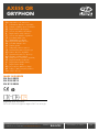 1
1
-
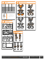 2
2
-
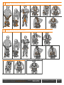 3
3
-
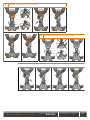 4
4
-
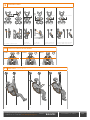 5
5
-
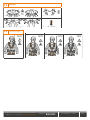 6
6
-
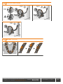 7
7
-
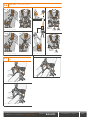 8
8
-
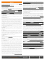 9
9
-
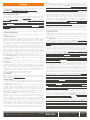 10
10
-
 11
11
-
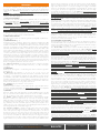 12
12
-
 13
13
-
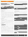 14
14
-
 15
15
-
 16
16
-
 17
17
-
 18
18
-
 19
19
-
 20
20
-
 21
21
-
 22
22
-
 23
23
-
 24
24
-
 25
25
-
 26
26
-
 27
27
-
 28
28
-
 29
29
-
 30
30
-
 31
31
-
 32
32
-
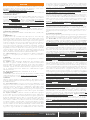 33
33
-
 34
34
-
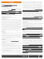 35
35
-
 36
36
-
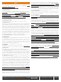 37
37
-
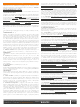 38
38
-
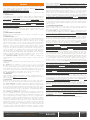 39
39
-
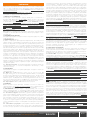 40
40
-
 41
41
-
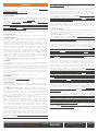 42
42
-
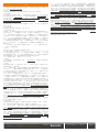 43
43


Climbing Technology 7H164 Instrucțiuni de utilizare
- Tip
- Instrucțiuni de utilizare
- Acest manual este potrivit și pentru
în alte limbi
Lucrări înrudite
-
Climbing Technology 7H161 Instrucțiuni de utilizare
-
-
-
-
-
-
-
-
-