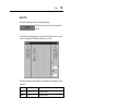
Yamaha DME 32 Manualul proprietarului
- Categorie
- Mixere audio
- Tip
- Manualul proprietarului
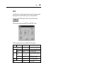
Acest manual este potrivit și pentru

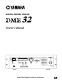
DIGITAL MIXING ENGINE
Owner’s Manual
E
Keep This Manual For Future Reference.
SCENE NO. CONFIGURATION
48kHz
LOCK
EMERGENCY
44.1kHz
SCENE
COMPONENT PARAMETER
UTILITY
VALUE
CARD
USER DEFINE
PROTECT
INC
DEC
DIGITAL MIXING ENGINE
POWER
ON OFF
7 8 9
4 5 6
1 2
0
STORE RECALL
3
SCENE RECALLDATA
XDigitalXMixingXEngine
XXXXXYAMAHAXDME32
88

FCC INFORMATION (U.S.A.)
1. IMPORTANT NOTICE: DO NOT MODIFY THIS UNIT! This product, when installed as indicated in the instructions contained in this manual, meets FCC
requirements. Modifications not expressly approved by Yamaha may void your authority, granted by the FCC, to use the product.
2. IMPORTANT: When connecting this product to accessories and/or another product use only high quality shielded cables. Cable/s supplied with this product MUST
be used. Follow all installation instructions. Failure to follow instructions could void your FCC authorization to use this product in the USA.
3. NOTE: This product has been tested and found to comply with the requirements listed in FCC Regulations, Part 15 for Class “B” digital devices. Compliance with
these requirements provides a reasonable level of assurance that your use of this product in a residential environment will not result in harmful interference with
other electronic devices. This equipment generates/uses radio frequencies and, if not installed and used according to the instructions found in the users manual, may
cause interference harmful to the operation of other electronic devices. Compliance with FCC regulations does not guarantee that interference will not occur in all
installations. If this product is found to be the source of interference, which can be determined by turning the unit “OFF” and “ON”, please try to eliminate the
problem by using one of the following measures: Relocate either this product or the device that is being affected by the interference. Utilize power outlets that are on
different branch (circuit breaker or fuse) circuits or install AC line filter/s. In the case of radio or TV interference, relocate/reorient the antenna. If the antenna lead-in
is 300 ohm ribbon lead, change the lead-in to coaxial type cable. If these corrective measures do not produce satisfactory results, please contact the local retailer
authorized to distribute this type of product. If you can not locate the appropriate retailer, please contact Yamaha Corporation of America, Electronic Service
Division, 6600 Orangethorpe Ave, Buena Park, CA 90620
The above statements apply ONLY to those products distributed by Yamaha Corporation of America or its subsidiaries.
WARNING: THIS APPARATUS MUST BE EARTHED
IMPORTANT
THE WIRES IN THIS MAINS LEAD ARE COLOURED IN
ACCORDANCE WITH THE FOLLOWING CODE:
GREEN-AND-YELLOW : EARTH
BLUE : NEUTRAL
BROWN : LIVE
As the colours of the wires in the mains lead of this apparatus may
not correspond with the coloured markings identifying the terminals in
your plug, proceed as follows:
The wire which is coloured GREEN and YELLOW must be
connected to the terminal in the plug which is marked by the letter E
or by the safety earth symbol or coloured GREEN and YELLOW.
The wire which is coloured BLUE must be connected to the terminal
which is marked with the letter N or coloured BLACK.
The wire which is coloured BROWN must be connected to the
terminal which is marked with the letter L or coloured RED.
* This applies only to products distributed by YAMAHA KEMBLE
MUSIC (U.K.) LTD.
ADVARSEL!
Lithiumbatteri—Eksplosionsfare ved fejlagtig
håndtering. Udskiftning må kun ske med batteri
af samme fabrikat og type. Levér det brugte
batteri tilbage til leverandoren.
VARNING
Explosionsfara vid felaktigt batteribyte. Använd
samma batterityp eller en ekvivalent typ som
rekommenderas av apparattillverkaren.
Kassera använt batteri enligt fabrikantens
instruktion.
VAROITUS
Paristo voi räjähtää, jos se on virheellisesti
asennettu. Vaihda paristo ainoastaan
laitevalmistajan suosittelemaan tyyppiin. Hävitä
käytetty paristo valmistajan ohjeiden
mukaisesti.
NEDERLAND THE NETHERLANDS
● Dit apparaat bevat een lithium batterij voor geheugen
back-up.
● Raadpleeg uw leverancier over de verwijdering van de
batterij op het moment dat u het apparaat ann het einde
van de levensduur afdankt of de volgende Yamaha Service
Afdeiing:
Yamaha Music Nederland Service Afdeiing
Kanaalweg 18-G, 3526 KL UTRECHT
Tel. 030-2828425
● Gooi de batterij niet weg, maar lever hem in als KCA.
● This apparatus contains a lithium battery for memory
back-up.
● For the removal of the battery at the moment of the
disposal at the end of the service life please consult your
retailer or Yamaha Service Center as follows:
Yamaha Music Nederland Service Center
Address: Kanaalweg 18-G, 3526 KL
UTRECHT
Tel: 030-2828425
● Do not throw away the battery. Instead, hand it in as small
chemical waste.

i
DME32—Owner’s Manual
Important Information
Read the Following Before Using the DME32
Warnings
• Do not subject the DME32 to extreme temperatures, humidity, direct sunlight, or dust,
which could be a potential fire or electrical shock hazard.
• Do not allow water to enter the DME32 or allow it to become wet. Fire or electrical
shock may result.
• Do not place a container with liquid or small metal objects on top of this unit. Liquid
or metal objects inside this unit are a fire and electrical shock hazard.
• Connect the power cord only to an AC outlet of the type stated in this Owner’s Manual
or as marked on the DME32. Failure to do so is a fire and electrical shock hazard.
• Hold the power-cord plug when disconnecting from an AC outlet. Never pull the cord.
A power cord damaged through pulling is a potential fire and electrical shock hazard.
• Do not touch the power plug with wet hands. Doing so is a potential electrical shock
hazard.
• Do not place heavy objects, including the DME32, on top of the power cord. A dam-
aged power cord is a fire and electrical shock hazard. In particular, be careful not to
place heavy objects on a power cord covered by a carpet.
• Do not scratch, bend, twist, pull, or heat the power cord. A damaged power cord is a
fire and electrical shock hazard.
• If the power cord is damaged (e.g., cut or a bare wire is exposed), ask your dealer for a
replacement. Using the DME32 with a damaged power cord is a fire and electrical shock
hazard.
• Do not plug several pieces of equipment into the same AC outlet. This may overload
the AC outlet, and could be a fire or electrical shock hazard. It may also affect the per-
formance of some equipment.
• If you notice any abnormality, such as smoke, odor, or noise, or if a foreign object or
liquid gets inside the DME32, turn it off immediately. Remove the power cord from the
AC outlet and consult your dealer for repair. Using the DME32 in this condition is a fire
and electrical shock hazard.
• Do not place small objects on top of the DME32. Metal objects falling inside the
DME32 is a fire and electrical shock hazard.
• If a foreign object or water gets inside the DME32, turn it off immediately. Remove the
power cord from the AC outlet and consult your dealer for repair. Using the DME32 in
this condition is a potential fire and electrical shock hazard.
• Should the DME32 be dropped or the cabinet be damaged, turn off the power, remove
the power plug from the AC outlet, and contact your dealer. If you continue using the
DME32 without heeding this instruction, fire or electrical shock may result.
• Do not remove the DME32’s cover. You could receive an electrical shock. If you think
internal inspection, maintenance, or repair is necessary, contact your dealer.
• Do not attempt to modify the DME32. This is a potential fire and electrical shock hazard.
• Do not block the DME32 ventilation slots. Blocking the ventilation slots is a potential
fire hazard.

ii
DME32—Owner’s Manual
Cautions
• Allow enough free space around the DME32 for normal ventilation. This should be
10 cm at the sides, 15 cm behind, and 30 cm above. These distances should also be
adopted when rack-mounting the DME32. For normal ventilation during use, remove
the rear of the rack or open a ventilation hole. If the airflow is not adequate, the DME32
will heat up inside and may cause a fire.
• Use the DME32 in a environment with a free-air temperature of between 10˚C and
35˚C (50˚F and 95˚F).
• Turn off all audio equipment when connecting to the DME32, and use only the cables
specified in the relevant owner’s manuals.
• If you plan not to use the DME32 for a long period of time, remove the power cord from
the AC outlet. Leaving the DME32 connected is a potential fire hazard.
• Do not use benzene, thinner, cleaning detergent, or a chemical cloth to clean the
DME32. Use only a soft, dry cloth.
• If the DME32 is stored in a cold place (e.g., overnight in a car), and then moved to a
warmer environment, or the temperature rises sharply, condensation may form inside
the DME32, which may affect performance. In such cases, the DME32 should be
allowed to acclimatize for about one hour before use.
• When the wordclock source is changed on the wordclock master device (e.g., AD824 or
DME32), noise may occur from the DME32’s analog outputs, especially if an MY8-AT
I/O card is installed, so turn down your power amps, or turn off the DME32 before-
hand, otherwise any connected speakers may be damaged.
• If the DME32 displays the message “Warning Low Battery” when it’s turned on, contact
your Yamaha dealer as soon as possible and ask them to replace the internal backup bat-
tery. Although the DME32 will continue to work in this condition, any configuration
data will be lost. It’s recommended that you save any configuration data using DME
Manager or a PC Card before replacing the battery.
Interference
The DME32 uses high-frequency digital circuits that may cause interference on radio
and television equipment located nearby. If interference is a problem, relocate the
affected equipment.
DME32 Exclusion of Certain Responsibility
Manufacturer, importer, or dealer shall not be liable for any incidental damages includ-
ing personal injury or any other damages caused by improper use or operation of the
DME32.

iii
DME32—Owner’s Manual
Package Contents
The DME32 package contains the following items. Contact your Yamaha dealer if you
are missing an item.
• DME32 Digital Mixing Engine
• CD-ROM (DME Manager software)
• 9-pin D-sub crossed cable (PC connection)
• 16-pin Euro-block plug (GPI interface)
• Power cord
• This manual
Trademarks
ADAT MultiChannel Optical Digital Interface is a trademark and ADAT and Alesis are
registered trademarks of Alesis Corporation. Intel and Pentium are registered trade-
marks and MMX is a trademark of Intel Corporation. Tascam Digital Interface is a
trademark and Tascam and Teac are registered trademarks of Teac Corporation. Win-
dows is a trademark of Microsoft Corporation. Yamaha is a trademark of Yamaha Cor-
poration. All other trademarks are the property of their respective holders and are
hereby acknowledged.
Copyright
No part of the DME32 or DME Manager software or this Owner’s Manual may be
reproduced or distributed in any form or by any means without the prior written
authorization of Yamaha Corporation.
© 2000 Yamaha Corporation. All rights reserved.
Yamaha Web Site
Information about the DME32 and other Yamaha professional audio products is avail-
able on the Yamaha Professional Audio Web site at:
<http://www.yamaha.co.jp/product/proaudio/homeenglish/>.

Contents v
DME32—Owner’s Manual
Contents
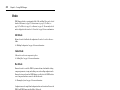
1 Welcome . . . . . . . . . . . . . . . . . . . . . . . . . . . . . . . . . 1
Welcome . . . . . . . . . . . . . . . . . . . . . . . . . . . . . . . . . . . . . . . . . . . . . . . . . . . 2
The DME32 in a Nutshell . . . . . . . . . . . . . . . . . . . . . . . . . . . . . . . . . . . . . 2
DME32 Features . . . . . . . . . . . . . . . . . . . . . . . . . . . . . . . . . . . . . . . . . . . . . 4
DME Manager Features . . . . . . . . . . . . . . . . . . . . . . . . . . . . . . . . . . . . . . . 6
About this Manual . . . . . . . . . . . . . . . . . . . . . . . . . . . . . . . . . . . . . . . . . . . 7
Installing the DME32 . . . . . . . . . . . . . . . . . . . . . . . . . . . . . . . . . . . . . . . . . 7
2 Getting Started . . . . . . . . . . . . . . . . . . . . . . . . . . . . 9
First Steps . . . . . . . . . . . . . . . . . . . . . . . . . . . . . . . . . . . . . . . . . . . . . . . . . 10
Connecting to a PC . . . . . . . . . . . . . . . . . . . . . . . . . . . . . . . . . . . . . . . . . 10
Connecting the Power Cord . . . . . . . . . . . . . . . . . . . . . . . . . . . . . . . . . . 11
Turning On & Off the DME32 . . . . . . . . . . . . . . . . . . . . . . . . . . . . . . . . 11
Installing DME Manager . . . . . . . . . . . . . . . . . . . . . . . . . . . . . . . . . . . . . 12
Upgrading & Reinstalling DME Manager . . . . . . . . . . . . . . . . . . . . . . . 12
Starting DME Manager . . . . . . . . . . . . . . . . . . . . . . . . . . . . . . . . . . . . . . 12
Quitting DME Manager . . . . . . . . . . . . . . . . . . . . . . . . . . . . . . . . . . . . . 13
DME Manager & Windows . . . . . . . . . . . . . . . . . . . . . . . . . . . . . . . . . . . 13
Installing the USB Driver . . . . . . . . . . . . . . . . . . . . . . . . . . . . . . . . . . . . 13
Checking the Driver is Installed Correctly . . . . . . . . . . . . . . . . . . . . . . . 14
USB Operating Notes . . . . . . . . . . . . . . . . . . . . . . . . . . . . . . . . . . . . . . . 14
3 Touring the DME32 . . . . . . . . . . . . . . . . . . . . . . . . 15
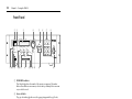
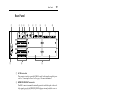
Front Panel . . . . . . . . . . . . . . . . . . . . . . . . . . . . . . . . . . . . . . . . . . . . . . . . 16
Rear Panel . . . . . . . . . . . . . . . . . . . . . . . . . . . . . . . . . . . . . . . . . . . . . . . . . 19
4 Touring DME Manager . . . . . . . . . . . . . . . . . . . . . 21
Modes . . . . . . . . . . . . . . . . . . . . . . . . . . . . . . . . . . . . . . . . . . . . . . . . . . . . 22
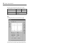
Main Window . . . . . . . . . . . . . . . . . . . . . . . . . . . . . . . . . . . . . . . . . . . . . 23
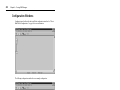
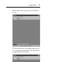
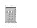
Configuration Windows . . . . . . . . . . . . . . . . . . . . . . . . . . . . . . . . . . . . . 26
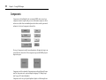
Components . . . . . . . . . . . . . . . . . . . . . . . . . . . . . . . . . . . . . . . . . . . . . . . 30
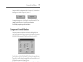
Component Control Windows . . . . . . . . . . . . . . . . . . . . . . . . . . . . . . . . 31
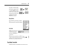
Run Mode Controller . . . . . . . . . . . . . . . . . . . . . . . . . . . . . . . . . . . . . . . 33
Other Windows . . . . . . . . . . . . . . . . . . . . . . . . . . . . . . . . . . . . . . . . . . . . 33
Touring the Menus . . . . . . . . . . . . . . . . . . . . . . . . . . . . . . . . . . . . . . . . . 34
Component List . . . . . . . . . . . . . . . . . . . . . . . . . . . . . . . . . . . . . . . . . . . . 40
Tool Palette . . . . . . . . . . . . . . . . . . . . . . . . . . . . . . . . . . . . . . . . . . . . . . . . 41
Alt Menu . . . . . . . . . . . . . . . . . . . . . . . . . . . . . . . . . . . . . . . . . . . . . . . . . . 41
Keyboard Shortcuts . . . . . . . . . . . . . . . . . . . . . . . . . . . . . . . . . . . . . . . . . 42
5 Building Configurations . . . . . . . . . . . . . . . . . . . . 43
How to Build & Edit Configurations . . . . . . . . . . . . . . . . . . . . . . . . . . . 44
Selecting Edit Mode . . . . . . . . . . . . . . . . . . . . . . . . . . . . . . . . . . . . . . . . . 45
Opening New Configuration Windows . . . . . . . . . . . . . . . . . . . . . . . . . 45
Opening Saved Configurations . . . . . . . . . . . . . . . . . . . . . . . . . . . . . . . . 46
Selecting Open Configuration Windows . . . . . . . . . . . . . . . . . . . . . . . . 46
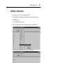
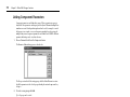
Adding Components . . . . . . . . . . . . . . . . . . . . . . . . . . . . . . . . . . . . . . . . 47

vi Contents
DME32—Owner’s Manual
Editing Components . . . . . . . . . . . . . . . . . . . . . . . . . . . . . . . . . . . . . . . . 48
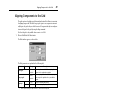
Aligning Components to the Grid . . . . . . . . . . . . . . . . . . . . . . . . . . . . . 49
Zooming Configuration Windows . . . . . . . . . . . . . . . . . . . . . . . . . . . . . 50
Selecting Cable Mode . . . . . . . . . . . . . . . . . . . . . . . . . . . . . . . . . . . . . . . 51
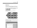
Adding Wires . . . . . . . . . . . . . . . . . . . . . . . . . . . . . . . . . . . . . . . . . . . . . . 51
Deleting Wires . . . . . . . . . . . . . . . . . . . . . . . . . . . . . . . . . . . . . . . . . . . . . 56
Working with Multiple-Unit Configurations . . . . . . . . . . . . . . . . . . . . 58
Resizing Sections of the Configuration Window . . . . . . . . . . . . . . . . . 59
Saving Configurations . . . . . . . . . . . . . . . . . . . . . . . . . . . . . . . . . . . . . . . 60
Saving Configurations under a New Name . . . . . . . . . . . . . . . . . . . . . . 60
Closing Configurations . . . . . . . . . . . . . . . . . . . . . . . . . . . . . . . . . . . . . . 60
Compiling Configurations . . . . . . . . . . . . . . . . . . . . . . . . . . . . . . . . . . . 61
Sending Configurations to the DME32 . . . . . . . . . . . . . . . . . . . . . . . . . 62
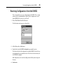
Receiving Configurations from the DME32 . . . . . . . . . . . . . . . . . . . . . 63
6 Running the System . . . . . . . . . . . . . . . . . . . . . . . . 65
Selecting Run Mode . . . . . . . . . . . . . . . . . . . . . . . . . . . . . . . . . . . . . . . . . 66
Run Mode Controller . . . . . . . . . . . . . . . . . . . . . . . . . . . . . . . . . . . . . . . 67
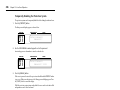
Editing Component Parameters . . . . . . . . . . . . . . . . . . . . . . . . . . . . . . . 69
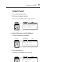
Storing Scenes . . . . . . . . . . . . . . . . . . . . . . . . . . . . . . . . . . . . . . . . . . . . . . 70
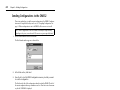
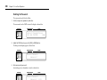
Recalling Scenes . . . . . . . . . . . . . . . . . . . . . . . . . . . . . . . . . . . . . . . . . . . . 72
Recalling Configurations . . . . . . . . . . . . . . . . . . . . . . . . . . . . . . . . . . . . . 74
7 Other DME Designer Functions . . . . . . . . . . . . . . . 75
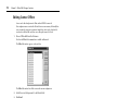
Editing Scenes Offline . . . . . . . . . . . . . . . . . . . . . . . . . . . . . . . . . . . . . . . 76
Linking Component Parameters . . . . . . . . . . . . . . . . . . . . . . . . . . . . . . 78
Customizing Component Properties . . . . . . . . . . . . . . . . . . . . . . . . . . . 80
Changing the Size of Rotary Controls & Sliders . . . . . . . . . . . . . . . . . . 82
Using Password Protection . . . . . . . . . . . . . . . . . . . . . . . . . . . . . . . . . . . 83
Assigning the User Define Button . . . . . . . . . . . . . . . . . . . . . . . . . . . . . 86
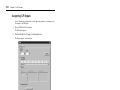
Printing . . . . . . . . . . . . . . . . . . . . . . . . . . . . . . . . . . . . . . . . . . . . . . . . . . . 87
8 Component Guide Part I . . . . . . . . . . . . . . . . . . . . 89
Automatic Mixer . . . . . . . . . . . . . . . . . . . . . . . . . . . . . . . . . . . . . . . . . . . 90
Cascade . . . . . . . . . . . . . . . . . . . . . . . . . . . . . . . . . . . . . . . . . . . . . . . . . . . 92
Crossover . . . . . . . . . . . . . . . . . . . . . . . . . . . . . . . . . . . . . . . . . . . . . . . . . 93
Crossover Processor . . . . . . . . . . . . . . . . . . . . . . . . . . . . . . . . . . . . . . . . . 102
Delay . . . . . . . . . . . . . . . . . . . . . . . . . . . . . . . . . . . . . . . . . . . . . . . . . . . . . 120
Delayed Mixer . . . . . . . . . . . . . . . . . . . . . . . . . . . . . . . . . . . . . . . . . . . . . 122
Dynamics . . . . . . . . . . . . . . . . . . . . . . . . . . . . . . . . . . . . . . . . . . . . . . . . . 125
9 Component Guide Part II . . . . . . . . . . . . . . . . . . . 141
Effect . . . . . . . . . . . . . . . . . . . . . . . . . . . . . . . . . . . . . . . . . . . . . . . . . . . . . 142
EQ . . . . . . . . . . . . . . . . . . . . . . . . . . . . . . . . . . . . . . . . . . . . . . . . . . . . . . . 162
Fader . . . . . . . . . . . . . . . . . . . . . . . . . . . . . . . . . . . . . . . . . . . . . . . . . . . . . 165
Filter . . . . . . . . . . . . . . . . . . . . . . . . . . . . . . . . . . . . . . . . . . . . . . . . . . . . . 166
Input/Output . . . . . . . . . . . . . . . . . . . . . . . . . . . . . . . . . . . . . . . . . . . . . . 170
Matrix Mixer . . . . . . . . . . . . . . . . . . . . . . . . . . . . . . . . . . . . . . . . . . . . . . 171
Meter . . . . . . . . . . . . . . . . . . . . . . . . . . . . . . . . . . . . . . . . . . . . . . . . . . . . . 174
Misc . . . . . . . . . . . . . . . . . . . . . . . . . . . . . . . . . . . . . . . . . . . . . . . . . . . . . . 175

Contents vii
DME32—Owner’s Manual
Pan . . . . . . . . . . . . . . . . . . . . . . . . . . . . . . . . . . . . . . . . . . . . . . . . . . . . . . . 178
Router . . . . . . . . . . . . . . . . . . . . . . . . . . . . . . . . . . . . . . . . . . . . . . . . . . . . 187
Switch . . . . . . . . . . . . . . . . . . . . . . . . . . . . . . . . . . . . . . . . . . . . . . . . . . . . 189
User Control . . . . . . . . . . . . . . . . . . . . . . . . . . . . . . . . . . . . . . . . . . . . . . . 190
User Module . . . . . . . . . . . . . . . . . . . . . . . . . . . . . . . . . . . . . . . . . . . . . . . 193
10 Front Panel Operation . . . . . . . . . . . . . . . . . . . . . . 197
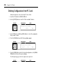
Recalling Configurations . . . . . . . . . . . . . . . . . . . . . . . . . . . . . . . . . . . . . 198
Storing Scenes . . . . . . . . . . . . . . . . . . . . . . . . . . . . . . . . . . . . . . . . . . . . . . 199
Recalling Scenes . . . . . . . . . . . . . . . . . . . . . . . . . . . . . . . . . . . . . . . . . . . . 200
Editing Parameters & the User Define Button . . . . . . . . . . . . . . . . . . . 201
Restricting Access to the DME32 . . . . . . . . . . . . . . . . . . . . . . . . . . . . . . 203
Selecting the Wordclock Source . . . . . . . . . . . . . . . . . . . . . . . . . . . . . . . 209
Checking the I/O Slots . . . . . . . . . . . . . . . . . . . . . . . . . . . . . . . . . . . . . . . 210
Initializing the DME32 . . . . . . . . . . . . . . . . . . . . . . . . . . . . . . . . . . . . . . 210
Checking the Firmware Version & Battery . . . . . . . . . . . . . . . . . . . . . . 210
11 GPI Interface . . . . . . . . . . . . . . . . . . . . . . . . . . . . . 211
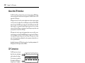
About the GPI Interface . . . . . . . . . . . . . . . . . . . . . . . . . . . . . . . . . . . . . 212
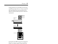
GPI Connectors . . . . . . . . . . . . . . . . . . . . . . . . . . . . . . . . . . . . . . . . . . . . 212
Assigning GPI Inputs . . . . . . . . . . . . . . . . . . . . . . . . . . . . . . . . . . . . . . . . 214
Assigning GPI Outputs . . . . . . . . . . . . . . . . . . . . . . . . . . . . . . . . . . . . . . 217
Emergency Mode . . . . . . . . . . . . . . . . . . . . . . . . . . . . . . . . . . . . . . . . . . . 220
12 PC Cards . . . . . . . . . . . . . . . . . . . . . . . . . . . . . . . . 221
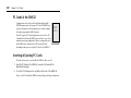
PC Cards & the DME32 . . . . . . . . . . . . . . . . . . . . . . . . . . . . . . . . . . . . . 222
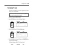
Inserting & Ejecting PC Cards . . . . . . . . . . . . . . . . . . . . . . . . . . . . . . . . 222
Formatting PC Cards . . . . . . . . . . . . . . . . . . . . . . . . . . . . . . . . . . . . . . . . 223
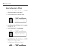
Saving Configurations to PC Cards . . . . . . . . . . . . . . . . . . . . . . . . . . . . 224
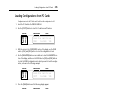
Loading Configurations from PC Cards . . . . . . . . . . . . . . . . . . . . . . . . 225
Deleting Configurations from PC Cards . . . . . . . . . . . . . . . . . . . . . . . . 226
13 Wordclocks . . . . . . . . . . . . . . . . . . . . . . . . . . . . . . 227
Wordclocks & the DME32 . . . . . . . . . . . . . . . . . . . . . . . . . . . . . . . . . . . 228
Wordclock Connections . . . . . . . . . . . . . . . . . . . . . . . . . . . . . . . . . . . . . 229
Selecting the Wordclock Source . . . . . . . . . . . . . . . . . . . . . . . . . . . . . . . 229
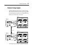
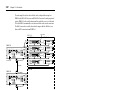
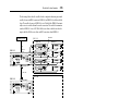
Wordclock Hookup Examples . . . . . . . . . . . . . . . . . . . . . . . . . . . . . . . . 231
Terminating BNC Wordclock Distribution . . . . . . . . . . . . . . . . . . . . . 234
14 Multiple DME32s . . . . . . . . . . . . . . . . . . . . . . . . . . 235
About Multiple DME32s . . . . . . . . . . . . . . . . . . . . . . . . . . . . . . . . . . . . . 236
Multiple-Unit System Notes . . . . . . . . . . . . . . . . . . . . . . . . . . . . . . . . . . 236
Cascade Connections . . . . . . . . . . . . . . . . . . . . . . . . . . . . . . . . . . . . . . . . 237
Multiple-unit Hookup Examples . . . . . . . . . . . . . . . . . . . . . . . . . . . . . . 238
15 MIDI . . . . . . . . . . . . . . . . . . . . . . . . . . . . . . . . . . . . 241
MIDI & the DME32 . . . . . . . . . . . . . . . . . . . . . . . . . . . . . . . . . . . . . . . . . 242
MIDI Ports . . . . . . . . . . . . . . . . . . . . . . . . . . . . . . . . . . . . . . . . . . . . . . . . 242
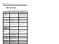
MIDI Settings . . . . . . . . . . . . . . . . . . . . . . . . . . . . . . . . . . . . . . . . . . . . . . 242
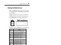
Assigning Scenes & Configurations to Program Changes . . . . . . . . . . 244
Assigning Component Parameters to Control Changes . . . . . . . . . . . 246

viii Contents
DME32—Owner’s Manual
Component Parameters & Parameter Changes . . . . . . . . . . . . . . . . . . 248
Saving MIDI Settings . . . . . . . . . . . . . . . . . . . . . . . . . . . . . . . . . . . . . . . . 249
Loading MIDI Settings . . . . . . . . . . . . . . . . . . . . . . . . . . . . . . . . . . . . . . 250
Deleting MIDI Settings . . . . . . . . . . . . . . . . . . . . . . . . . . . . . . . . . . . . . . 250
16 I/O Options . . . . . . . . . . . . . . . . . . . . . . . . . . . . . . 251
I/O Options & the DME32 . . . . . . . . . . . . . . . . . . . . . . . . . . . . . . . . . . . 252
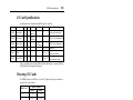
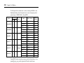
I/O Card Specifications . . . . . . . . . . . . . . . . . . . . . . . . . . . . . . . . . . . . . . 253
Choosing I/O Cards . . . . . . . . . . . . . . . . . . . . . . . . . . . . . . . . . . . . . . . . . 253
Installing I/O Cards . . . . . . . . . . . . . . . . . . . . . . . . . . . . . . . . . . . . . . . . . 255
AD824 & DA824 Converters . . . . . . . . . . . . . . . . . . . . . . . . . . . . . . . . . . 256
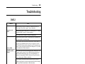
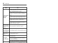
Troubleshooting . . . . . . . . . . . . . . . . . . . . . . . . . . . . . 261
DME32 . . . . . . . . . . . . . . . . . . . . . . . . . . . . . . . . . . . . . . . . . . . . . . . . . . . 261
DME Manager . . . . . . . . . . . . . . . . . . . . . . . . . . . . . . . . . . . . . . . . . . . . . 263
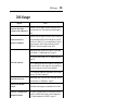
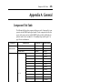
Appendix A: General . . . . . . . . . . . . . . . . . . . . . . . . . 265
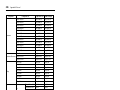
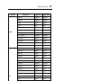
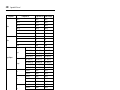
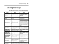
Component Title Table . . . . . . . . . . . . . . . . . . . . . . . . . . . . . . . . . . . . . . 265
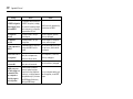
DME32 Error Messages . . . . . . . . . . . . . . . . . . . . . . . . . . . . . . . . . . . . . . 270
DME Manager Error Messages . . . . . . . . . . . . . . . . . . . . . . . . . . . . . . . . 271
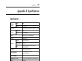
Appendix B: Specifications . . . . . . . . . . . . . . . . . . . . . 273
Specifications . . . . . . . . . . . . . . . . . . . . . . . . . . . . . . . . . . . . . . . . . . . . . . 273
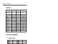
Control I/O . . . . . . . . . . . . . . . . . . . . . . . . . . . . . . . . . . . . . . . . . . . . . . . . 274
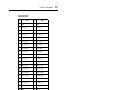
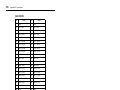
Connector Pin Assignments . . . . . . . . . . . . . . . . . . . . . . . . . . . . . . . . . . 274
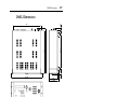
DME32 Dimensions . . . . . . . . . . . . . . . . . . . . . . . . . . . . . . . . . . . . . . . . 277
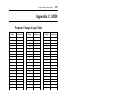
Appendix C: MIDI . . . . . . . . . . . . . . . . . . . . . . . . . . . . 279
Program Change Assign Table . . . . . . . . . . . . . . . . . . . . . . . . . . . . . . . . 279
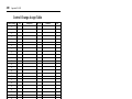
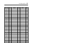
Control Change Assign Table . . . . . . . . . . . . . . . . . . . . . . . . . . . . . . . . . 280
MIDI Data Format . . . . . . . . . . . . . . . . . . . . . . . . . . . . . . . . . . . . . . . . . . 283
Glossary . . . . . . . . . . . . . . . . . . . . . . . . . . . . . . . . . . . 287
Index . . . . . . . . . . . . . . . . . . . . . . . . . . . . . . . . . . . . . . 289
MIDI Implementation Chart

Welcome 1
DME32—Owner’s Manual
Welcome
1
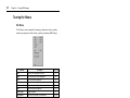
In this chapter...
Welcome . . . . . . . . . . . . . . . . . . . . . . . . . . . . . . . . . . . . . . . . . . . . . . . . . . . . . . . . . 2
The DME32 in a Nutshell . . . . . . . . . . . . . . . . . . . . . . . . . . . . . . . . . . . . . . . . . . . 2
DME32 Features . . . . . . . . . . . . . . . . . . . . . . . . . . . . . . . . . . . . . . . . . . . . . . . . . . . 4
DME Manager Features . . . . . . . . . . . . . . . . . . . . . . . . . . . . . . . . . . . . . . . . . . . . . 6
About this Manual . . . . . . . . . . . . . . . . . . . . . . . . . . . . . . . . . . . . . . . . . . . . . . . . . 7
Installing the DME32 . . . . . . . . . . . . . . . . . . . . . . . . . . . . . . . . . . . . . . . . . . . . . . . 7

2 Chapter 1—Welcome
DME32—Owner’s Manual
Welcome
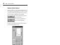
Thank you for choosing the Yamaha DME32 Digital Mixing Engine.
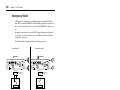
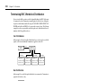
The DME32 Digital Mixing Engine and DME Manager software allow sound-system
installers to custom build systems to meet the specific requirements of almost any
installation. Entire systems from input through to output can be designed using DME
Manager and then transferred to the DME32, which can then be used as a standalone
processor. Typical applications include installed sound systems, submixing, loud-
speaker system controllers, matrix/routing, and multi-effects processing.
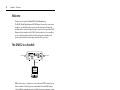
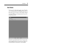
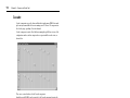
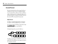
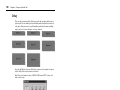
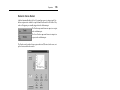
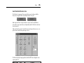
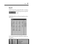
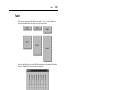
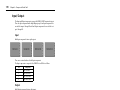
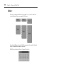
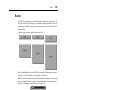
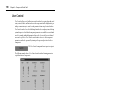
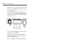
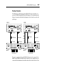
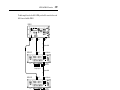
The DME32 in a Nutshell
DME32 audio systems, or configurations as they’re known in DME32 terminology, are
built in an intuitive “block diagram” style using Yamaha’s dedicated DME Manager
software. Building configurations consists of adding the necessary components, wiring
them together, compiling, and then transferring that information to the DME32, using
either RS232/RS422, USB (Universal Serial Bus), or PC Cards.
Once programmed, the DME32 operates as a standalone processor and the PC can be
disconnected, although it can be connected permanently in applications where
real-time control from DME Manager is desirable. Even then, if the PC connection is
lost for some reason, the DME32 just keeps on going.
Components form the building blocks in configurations. Some components are com-
plete audio processors, such as mixers, compressors, effects, and crossovers, while oth-
ers are individual parts, such as faders, switches, pan controls, and meters. System
designers can create their own custom components using the User modules.
DME Manager operates in one of three modes: Edit, Cable, or Run. Edit mode is used
mainly to build and edit configurations, although it can also be used to edit and preview
scenes offline. Cable mode is for wiring components together. Run mode is used to con-
trol the DME32 system in real time, which includes editing component parameters,
storing and recalling scenes, and recalling configurations. In Run mode, actions per-
formed on DME Manager are reflected on the DME32 and vice versa.
The DME32 can store two configurations: A and B. Additional configurations can be
stored on PC Cards. Each configuration can store up to 99 scenes, or snapshots of every
component parameter setting in the configuration. Configurations and scenes can be
recalled from the DME32 front panel, DME Manager, MIDI, or the GPI interface. Con-
figurations and scenes can be titled from the PC keyboard for easy identification.
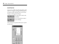
When operating as a standalone processor, various DME32 functions can controlled
from the front panel, including editing component parameters, storing and recalling
DME
Manager
32 outputs32 inputs
Control
SCENE NO. CONFIGURATION
48kHz
LOCK
EMERGENCY
44.1kHz
SCENE
COMPONENT PARAMETER
UTILITY
VALUE
CARD
USER DEFINE
PROTECT
INC
DEC
DIGITAL MIXING ENGINE
POWER
ON OFF
7 8 9
4 5 6
1 2
0
STORE RECALL
3
SCENE RECALLDATA
XDigitalXMixingX Engine
XXXXXYAMAHAXDME32
88

The DME32 in a Nutshell 3
DME32—Owner’s Manual
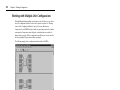
scenes, and recalling configurations. Direct access to a specific parameter is possible by
assigning it to the [USER DEFINE] button. The large, two-digit scene number display
indicates the current scene, while the 48-character LCD displays configuration and
scene titles, component and parameter names, parameter values, and so on. Unautho-
rized operation can be prevented by using the password protection.
The DME32 offers 32 inputs and 32 outputs via four mini YGDAI card slots. Optional
mini YGDAI (Yamaha General Digital Audio Interface) cards offer a variety of analog
and digital I/O configurations, with support for all the popular digital audio intercon-
nect formats, including AES/EBU, ADAT, and Tascam TDIF-1. Inputs and outputs can
be expanded in multiples of 32 by cascading additional DME32s. Up to four DME32s
can be cascaded, providing a maximum of 128 inputs and 128 outputs. Cascade com-
ponents offer bus-like signal distribution in multiple-unit systems and can also be used
for DSP power sharing between DME32s.
Superb sonic performance is achieved using 32-bit internal signal processing and a
48 kHz internal sampling rate. External sampling rates of between 39.69 kHz to
50.88 kHz are supported and can be set individually for each configuration.
Remote interaction between DME32 functions and custom-made controllers and
other equipment is possible using MIDI and the GPI interface, which offers 16 assign-
able inputs and 16 assignable outputs. Scenes and configurations can be recalled using
MIDI Program Change messages or the GPI interface. Component parameters can be
controlled by using MIDI Control Change messages, System Exclusive messages, or
custom-made controllers attached to the GPI interface.
See page 4 for a rundown of DME32 features, page 6 for DME Manager features.

4 Chapter 1—Welcome
DME32—Owner’s Manual
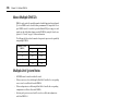
DME32 Features
Sonic Performance
• 32-bit internal signal processing
• 48 kHz internal sampling rate
• 39.69 kHz to 50.88 kHz external wordclock
Memories & Storage
• 2 configuration memories: A and B
• 99 scene memories per configuration
• Configurations and scenes can be titled from the PC keyboard for easy identification
• Store and transfer configurations on PC Cards
Flexible I/O
• 32 inputs, 32 outputs via four mini YGDAI slots
• Optional mini YGDAI cards offer a variety of analog and digital I/O configurations,
with support for all the popular digital audio interconnect formats, including
AES/EBU, ADAT, and Tascam TDIF-1.
• Analog I/O options include the Yamaha AD824 8-channel 24-bit A/D converter and
DA824 8-channel 24-bit D/A converter
Control Ports
• Switchable RS232/RS422 serial port for PC connection
• RS422 allows cable lengths of up to one kilometer (15 meters for RS232)
• Convenient front panel USB port for PC connection
• COM port for AD824 head-amp gain control
Multiple Units
• Cascade ports for multiple-unit operation with up to four DME32s
• I/O expansion in multiples of 32, with a maximum of four DME32s providing 128
inputs and 128 outputs
• 32 cascade buses allow bus-like signal distribution and power sharing between DME32s
Remote Control
• Configuration and scene recall using MIDI Program Changes
• Component parameter control using MIDI Control Changes or System Exclusive
• GPI interface with 16 assignable inputs, 16 assignable outputs
• Emergency mode assignable to any GPI input

DME32 Features 5
DME32—Owner’s Manual
Standalone Operation
• DME Manager can be disconnected once the DME32 has been programmed
• Dedicated keypad for scene store and recall
• Data wheel and INC/DEC buttons for component parameter editing
• Assignable [USER DEFINE] button for quick parameter access
Others
• Large, 2-digit scene number indicator
• 48-character LCD display
• Password protection prevents unauthorized operation
• Wordclock I/O and switchable termination for master/slave operation
• 3U rack space

6 Chapter 1—Welcome
DME32—Owner’s Manual
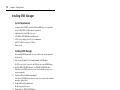
DME Manager Features
Components
• Processor components include crossovers, dynamics, filters, GEQ, PEQ, effects, etc
• Part-type components include faders, meters, switches, pan controls, etc
• Create custom components using User Modules
• Copy frequently used controls to custom control windows
• Customize the size of rotary controls and sliders
Edit mode
• Drag and drop components onto configuration windows
• Use standard cut, copy, and paste commands to edit components
• Customize component appearance, including title, size, and color
• DSP power meter indicates approximate processor usage
• Align and snap components to the variable grid
• Zoom in to see components in detail or zoom out to see more of a configuration
Cable Mode
• Wire components by dragging wires between input and output nodes
• Wire component nodes individually or in multiples
Run mode
• Real-time control using DME Manager
• Edit component parameters, recall and store scenes, and recall configurations
• Actions performed on DME Manager are reflected on the DME32 and vice versa
Offline Operation
• Build and edit configurations off-site
• Edit, title, and delete scenes offline
• Preview scenes offline
Configurations & Scenes
• Title configurations and scenes from the PC keyboard
• Save configurations to any media available to Windows, including PC Cards
• Open multiple configurations simultaneously
Easy Operation
• Drag rotary controls and sliders
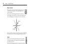
• Set PEQ parameters by dragging points on an EQ curve
• Context-sensitive shortcut menu containing frequently used commands
• Floating tool palette and Alt-click mode menu for quick mode switching

About this Manual 7
DME32—Owner’s Manual
Other Features
• Up to 32 parameter-link groups for fader grouping, stereo signal control, or crossover
frequency control in multiple-speaker systems
• Link parameters across cascaded DME32s
• 3-level password protection allows full access, limited access, or no access
• Print configuration information, including diagrams, component and parameter lists
About this Manual
This Owner’s Manual contains all the information you need in order to operate the
DME32 Digital Mixing Engine and DME Manager. Use the table of contents to famil-
iarize yourself with the organization of this manual and locate topics. Use the index to
locate specific information. A glossary of DME32-related jargon is provided on
page 287.
In this manual, the DME32 Digital Mixing Engine and DME Manager software are
referred to as the “DME32” and “DME Manager” respectively. “PC” refers to an IBM
PC-compatible computer running a Windows operating system.
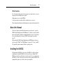
Installing the DME32
When mounting the DME32 in a rack, remove the DME32’s feet and leave adequate
ventilation space around the DME32 (at least 15 cm of free space behind). If the
DME32 is mounted in a portable rack case, keep the rear of the case open when using
the DME32 so as not to obstruct the free flow of air. Do not mount the DME32 above
equipment that produces a lot of heat, such as a power amplifier.

Getting Started 9
DME32—Owner’s Manual
Getting Started
2
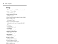
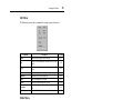
In this chapter...
First Steps . . . . . . . . . . . . . . . . . . . . . . . . . . . . . . . . . . . . . . . . . . . . . . . . . . . . . . . . 10
Connecting to a PC . . . . . . . . . . . . . . . . . . . . . . . . . . . . . . . . . . . . . . . . . . . . . . . 10
Connecting the Power Cord . . . . . . . . . . . . . . . . . . . . . . . . . . . . . . . . . . . . . . . . 11
Turning On & Off the DME32 . . . . . . . . . . . . . . . . . . . . . . . . . . . . . . . . . . . . . . 11
Installing DME Manager . . . . . . . . . . . . . . . . . . . . . . . . . . . . . . . . . . . . . . . . . . . 12
Upgrading & Reinstalling DME Manager . . . . . . . . . . . . . . . . . . . . . . . . . . . . . 12
Starting DME Manager . . . . . . . . . . . . . . . . . . . . . . . . . . . . . . . . . . . . . . . . . . . . 12
Quitting DME Manager . . . . . . . . . . . . . . . . . . . . . . . . . . . . . . . . . . . . . . . . . . . . 13
DME Manager & Windows . . . . . . . . . . . . . . . . . . . . . . . . . . . . . . . . . . . . . . . . . 13
Installing the USB Driver . . . . . . . . . . . . . . . . . . . . . . . . . . . . . . . . . . . . . . . . . . . 13
Checking the Driver is Installed Correctly . . . . . . . . . . . . . . . . . . . . . . . . . . . . . 14
USB Operating Notes . . . . . . . . . . . . . . . . . . . . . . . . . . . . . . . . . . . . . . . . . . . . . . 14

10 Chapter 2—Getting Started
DME32—Owner’s Manual
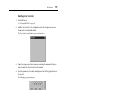
First Steps
Here’s how to get up and running with the DME32 system with the minimum of fuss.
1 Familiarize yourself with the DME32.
See “Touring the DME32” on page 15.
2 Install the required mini YGDAI I/O cards.
See “I/O Options” on page 251.
3 Connect your audio sources and other equipment to the inputs and outputs.
4 Connect the DME32 to your PC.
See “Connecting to a PC” on page 10.
5 Connect the power cord and turn on the DME32.
See “Connecting the Power Cord” on page 11 and “Turning On & Off the DME32” on
page 11.
6 Install DME Manager.
See “Installing DME Manager” on page 12.
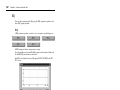
7 Start DME Manager.
See “Starting DME Manager” on page 12.
8 Familiarize yourself with DME Manager.
See “Touring DME Manager” on page 21.
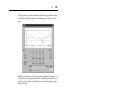
9 Build a configuration.
See “Building Configurations” on page 43.
10 Compile the configuration.
See “Compiling Configurations” on page 61.
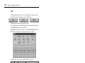
11 Transfer the configuration to the DME32.
See “Sending Configurations to the DME32” on page 62.
12 Take the configuration for a run.
See “Running the System” on page 65.
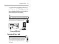
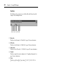
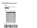
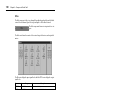
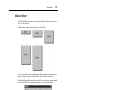
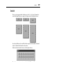
Connecting to a PC
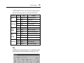
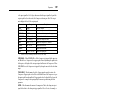
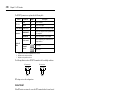
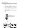
The DME32 can be connected to a PC by using standard RS232/RS422 serial connections or
USB (Universal Serial Bus). When the DME32 receives a command via the serial port, it
transmits a response to only the serial port. Likewise, when it receives a command via the
USB port, it transmits a response to only the USB port.
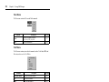
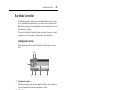
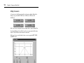
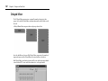
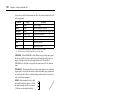
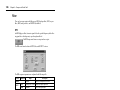
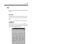
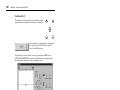
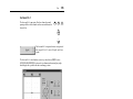
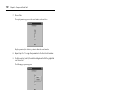
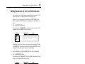
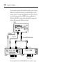
Serial Port
The PC CONTROL port features a switch for selecting
RS232 or RS422. These two serial port standards are virtu-
ally the same, the main difference being that RS422 is bal-
anced and therefore supports longer cable lengths. RS232
supports cable lengths of up to 15 meters, while RS422 sup-
ports lengths of up to 1 kilometer. Select the one that
matches your PC’s serial port.
PC CONTROL
RS
232C
RS
422
Serial cable
COM port
PC CONTROL port
12345678
12345678
910111213141516
910111213141516
SLOT
2
SLOT
4
SLOT
1
SLOT
3
CASCADE INCASCADE OUTCOMPC CONTROLMIDI
AC IN
WORD CLOCK
IN
OFFON
75Ω
OUT OUT IN
IN +V
OUT GND
GND
IN +V
OUT
RS
232C
RS
422

Connecting the Power Cord 11
DME32—Owner’s Manual
You can specify which COM port on your PC DME Manager uses, although you’ll need to
install DME Manager in order to do this. See “Installing DME Manager” on page 12 for more
information. Using a text editor, open the “setup.ini” file in the DME folder. Change the COM
parameter to match the number of the COM port you want to use. To use COM port 2, for
example, the setting should be “COM2” (without quotation marks).
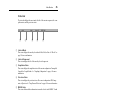
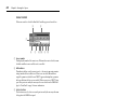
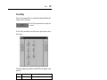
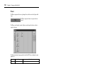
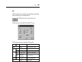
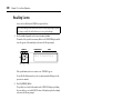
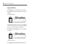
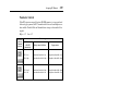
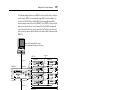
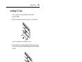
USB
The front panel USB port is a convenient way to connect a PC to the DME32 and
is ideal for systems where the DME32 rear panel is not easily accessible.
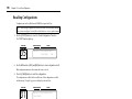
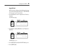
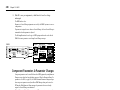
Connecting the Power Cord
Connect the socket-end of the supplied power cord to the AC IN socket on
the rear panel of the DME32. Connect the plug-end to a suitable AC wall out-
let, one that conforms to the power supply requirements stated on the
DME32 rear panel.
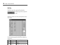
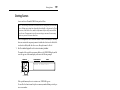
Turning On & Off the DME32
To prevent loud clicks and thumps in your speakers, turn on your audio
equipment in the following order (reverse this order when turning off
your equipment)—sound sources, mixer or recorder (e.g., 02R, DME32,
D24, etc.), power amplifiers.
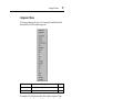
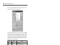
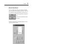
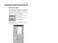
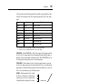
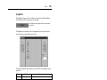
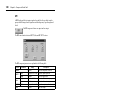
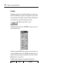
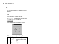
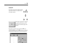
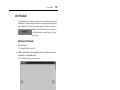
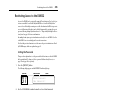
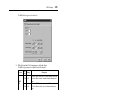
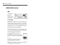
1 To turn on the DME32, press the [POWER] switch.
The following message appears for a few moments.
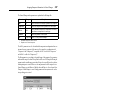
The number and title of the current configuration and scene appear on the display. The first
parameter of the first component is selected, unless the [USER DEFINE] button has been
assigned, in which case, the parameter assigned to that button is selected and the USER
DEFINE indicator lights up.
When the DME32 is turned on for the first time, or when it’s initialized, configuration mem-
ory A contains a simple configuration titled “Mtrx16.” This configuration is stored inside the
DME32 and can be overwritten by transferring another configuration from DME Manager.
2 To turn off the DME32, press the [POWER] switch.
Important: You need to install the USB driver in order to use the USB port. See page 13.
Warning: Turn off all equipment before making any power connections.
SCENE NO. CONFIGURATION
48kHz
LOCK
EMERGENCY
44.1kHz
SCENE
COMPONENT PARAMETER
UTILITY
VALUE
CARD
USER DEFINE
PROTECT
INC
DEC
DIGITAL MIXING ENGINE
POWER
ON OFF
7 8 9
4 5 6
1 2
0STORE RECALL
3
SCENE RECALLDATA
XDigitalX MixingXEngine
XXXXXYAMAHAXDME32
88
USB cable
USB port
USB port
AC IN
POWER
ON OFF
XDigitalXMixingXEngine
XXXXXYAMAHAXDME32

12 Chapter 2—Getting Started
DME32—Owner’s Manual
Installing DME Manager
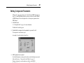
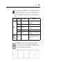
System Requirements
• A computer with a 200 MHz or faster Intel Pentium MMX processor or equivalent
• At least 32 MB of RAM (64 MB or more recommended)
• A hard disk with at least 20 MB of free space
• A CD-ROM or DVD-ROM drive (installation only)
• A VGA or better display (640 x 480, 256 color minimum)
• An RS232 or RS422 serial port or a USB port
• Windows 95/98
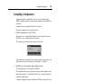
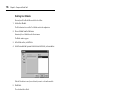
Installing DME Manager
Before installing DME Manager, make sure that your PC meets the system requirements
listed previously.
1 Turn on your PC and, if it’s not running already, start Windows.
The PC does not need to be connected to the DME32 in order to install DME Manager.
2 Insert the DME32 CD-ROM disc into your CD-ROM or DVD-ROM drive.
If the Windows CD-ROM Autorun feature is turned on, the installation start up screen
appears automatically.
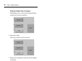
3 Continue with the installation as prompted.
If the Windows CD-ROM Autorun feature is not turned on, you must start the installation
manually, as explained below.
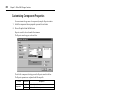
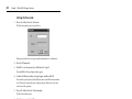
4 Double-click the My Computer icon.
The My Computer window opens.
5 Double-click the “DME32” CD-ROM icon.
The installation start up screen appears.
6 Continue with the installation as prompted.
When the installation process is complete, remove the CD-ROM disc from the CD-ROM
drive and return it to its case for safe keeping.
The installation program adds a DME item to the Windows Programs menu.
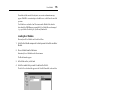
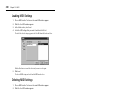
Upgrading & Reinstalling DME Manager
Before upgrading or reinstalling DME Manager, you must delete the previously installed ver-
sion as follows.
1 Use the “Add/Remove Programs” control panel to remove DME Manager.
2 Locate the “DME” folder and delete all the files inside it (do not delete the
“AddIn,” “Midi,” or “Module” folders or the files inside them).
Normally the “DME” folder is in “C:\Program Files.”
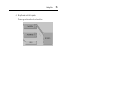
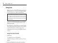
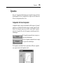
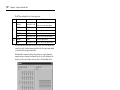
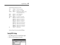
Starting DME Manager
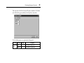
1 Click the Windows “Start” button and select Programs, DME.
DME Manager starts.
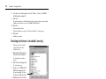
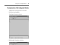
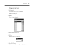
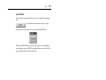
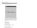
When DME Manager is started, it checks whether any active DME32s are connected, active
meaning connected and turned on. If an active DME32 containing configuration data is
detected, a message asking whether or not you want to receive the configuration data
appears. If you choose to receive it, all the configuration data in the DME32 is transferred to
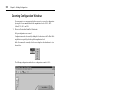
DME Manager and displayed in new configuration windows, and DME Manager switches to
Pagina se încarcă...
Pagina se încarcă...
Pagina se încarcă...
Pagina se încarcă...
Pagina se încarcă...
Pagina se încarcă...
Pagina se încarcă...
Pagina se încarcă...
Pagina se încarcă...
Pagina se încarcă...
Pagina se încarcă...
Pagina se încarcă...
Pagina se încarcă...
Pagina se încarcă...
Pagina se încarcă...
Pagina se încarcă...
Pagina se încarcă...
Pagina se încarcă...
Pagina se încarcă...
Pagina se încarcă...
Pagina se încarcă...
Pagina se încarcă...
Pagina se încarcă...
Pagina se încarcă...
Pagina se încarcă...
Pagina se încarcă...
Pagina se încarcă...
Pagina se încarcă...
Pagina se încarcă...
Pagina se încarcă...
Pagina se încarcă...
Pagina se încarcă...
Pagina se încarcă...
Pagina se încarcă...
Pagina se încarcă...
Pagina se încarcă...
Pagina se încarcă...
Pagina se încarcă...
Pagina se încarcă...
Pagina se încarcă...
Pagina se încarcă...
Pagina se încarcă...
Pagina se încarcă...
Pagina se încarcă...
Pagina se încarcă...
Pagina se încarcă...
Pagina se încarcă...
Pagina se încarcă...
Pagina se încarcă...
Pagina se încarcă...
Pagina se încarcă...
Pagina se încarcă...
Pagina se încarcă...
Pagina se încarcă...
Pagina se încarcă...
Pagina se încarcă...
Pagina se încarcă...
Pagina se încarcă...
Pagina se încarcă...
Pagina se încarcă...
Pagina se încarcă...
Pagina se încarcă...
Pagina se încarcă...
Pagina se încarcă...
Pagina se încarcă...
Pagina se încarcă...
Pagina se încarcă...
Pagina se încarcă...
Pagina se încarcă...
Pagina se încarcă...
Pagina se încarcă...
Pagina se încarcă...
Pagina se încarcă...
Pagina se încarcă...
Pagina se încarcă...
Pagina se încarcă...
Pagina se încarcă...
Pagina se încarcă...
Pagina se încarcă...
Pagina se încarcă...
Pagina se încarcă...
Pagina se încarcă...
Pagina se încarcă...
Pagina se încarcă...
Pagina se încarcă...
Pagina se încarcă...
Pagina se încarcă...
Pagina se încarcă...
Pagina se încarcă...
Pagina se încarcă...
Pagina se încarcă...
Pagina se încarcă...
Pagina se încarcă...
Pagina se încarcă...
Pagina se încarcă...
Pagina se încarcă...
Pagina se încarcă...
Pagina se încarcă...
Pagina se încarcă...
Pagina se încarcă...
Pagina se încarcă...
Pagina se încarcă...
Pagina se încarcă...
Pagina se încarcă...
Pagina se încarcă...
Pagina se încarcă...
Pagina se încarcă...
Pagina se încarcă...
Pagina se încarcă...
Pagina se încarcă...
Pagina se încarcă...
Pagina se încarcă...
Pagina se încarcă...
Pagina se încarcă...
Pagina se încarcă...
Pagina se încarcă...
Pagina se încarcă...
Pagina se încarcă...
Pagina se încarcă...
Pagina se încarcă...
Pagina se încarcă...
Pagina se încarcă...
Pagina se încarcă...
Pagina se încarcă...
Pagina se încarcă...
Pagina se încarcă...
Pagina se încarcă...
Pagina se încarcă...
Pagina se încarcă...
Pagina se încarcă...
Pagina se încarcă...
Pagina se încarcă...
Pagina se încarcă...
Pagina se încarcă...
Pagina se încarcă...
Pagina se încarcă...
Pagina se încarcă...
Pagina se încarcă...
Pagina se încarcă...
Pagina se încarcă...
Pagina se încarcă...
Pagina se încarcă...
Pagina se încarcă...
Pagina se încarcă...
Pagina se încarcă...
Pagina se încarcă...
Pagina se încarcă...
Pagina se încarcă...
Pagina se încarcă...
Pagina se încarcă...
Pagina se încarcă...
Pagina se încarcă...
Pagina se încarcă...
Pagina se încarcă...
Pagina se încarcă...
Pagina se încarcă...
Pagina se încarcă...
Pagina se încarcă...
Pagina se încarcă...
Pagina se încarcă...
Pagina se încarcă...
Pagina se încarcă...
Pagina se încarcă...
Pagina se încarcă...
Pagina se încarcă...
Pagina se încarcă...
Pagina se încarcă...
Pagina se încarcă...
Pagina se încarcă...
Pagina se încarcă...
Pagina se încarcă...
Pagina se încarcă...
Pagina se încarcă...
Pagina se încarcă...
Pagina se încarcă...
Pagina se încarcă...
Pagina se încarcă...
Pagina se încarcă...
Pagina se încarcă...
Pagina se încarcă...
Pagina se încarcă...
Pagina se încarcă...
Pagina se încarcă...
Pagina se încarcă...
Pagina se încarcă...
Pagina se încarcă...
Pagina se încarcă...
Pagina se încarcă...
Pagina se încarcă...
Pagina se încarcă...
Pagina se încarcă...
Pagina se încarcă...
Pagina se încarcă...
Pagina se încarcă...
Pagina se încarcă...
Pagina se încarcă...
Pagina se încarcă...
Pagina se încarcă...
Pagina se încarcă...
Pagina se încarcă...
Pagina se încarcă...
Pagina se încarcă...
Pagina se încarcă...
Pagina se încarcă...
Pagina se încarcă...
Pagina se încarcă...
Pagina se încarcă...
Pagina se încarcă...
Pagina se încarcă...
Pagina se încarcă...
Pagina se încarcă...
Pagina se încarcă...
Pagina se încarcă...
Pagina se încarcă...
Pagina se încarcă...
Pagina se încarcă...
Pagina se încarcă...
Pagina se încarcă...
Pagina se încarcă...
Pagina se încarcă...
Pagina se încarcă...
Pagina se încarcă...
Pagina se încarcă...
Pagina se încarcă...
Pagina se încarcă...
Pagina se încarcă...
Pagina se încarcă...
Pagina se încarcă...
Pagina se încarcă...
Pagina se încarcă...
Pagina se încarcă...
Pagina se încarcă...
Pagina se încarcă...
Pagina se încarcă...
Pagina se încarcă...
Pagina se încarcă...
Pagina se încarcă...
Pagina se încarcă...
Pagina se încarcă...
Pagina se încarcă...
Pagina se încarcă...
Pagina se încarcă...
Pagina se încarcă...
Pagina se încarcă...
Pagina se încarcă...
Pagina se încarcă...
Pagina se încarcă...
Pagina se încarcă...
Pagina se încarcă...
Pagina se încarcă...
Pagina se încarcă...
Pagina se încarcă...
Pagina se încarcă...
Pagina se încarcă...
Pagina se încarcă...
Pagina se încarcă...
Pagina se încarcă...
Pagina se încarcă...
Pagina se încarcă...
Pagina se încarcă...
Pagina se încarcă...
Pagina se încarcă...
Pagina se încarcă...
Pagina se încarcă...
Pagina se încarcă...
Pagina se încarcă...
Pagina se încarcă...
Pagina se încarcă...
Pagina se încarcă...
Pagina se încarcă...
Pagina se încarcă...
Pagina se încarcă...
Pagina se încarcă...
Pagina se încarcă...
Pagina se încarcă...
Pagina se încarcă...
-
 1
1
-
 2
2
-
 3
3
-
 4
4
-
 5
5
-
 6
6
-
 7
7
-
 8
8
-
 9
9
-
 10
10
-
 11
11
-
 12
12
-
 13
13
-
 14
14
-
 15
15
-
 16
16
-
 17
17
-
 18
18
-
 19
19
-
 20
20
-
 21
21
-
 22
22
-
 23
23
-
 24
24
-
 25
25
-
 26
26
-
 27
27
-
 28
28
-
 29
29
-
 30
30
-
 31
31
-
 32
32
-
 33
33
-
 34
34
-
 35
35
-
 36
36
-
 37
37
-
 38
38
-
 39
39
-
 40
40
-
 41
41
-
 42
42
-
 43
43
-
 44
44
-
 45
45
-
 46
46
-
 47
47
-
 48
48
-
 49
49
-
 50
50
-
 51
51
-
 52
52
-
 53
53
-
 54
54
-
 55
55
-
 56
56
-
 57
57
-
 58
58
-
 59
59
-
 60
60
-
 61
61
-
 62
62
-
 63
63
-
 64
64
-
 65
65
-
 66
66
-
 67
67
-
 68
68
-
 69
69
-
 70
70
-
 71
71
-
 72
72
-
 73
73
-
 74
74
-
 75
75
-
 76
76
-
 77
77
-
 78
78
-
 79
79
-
 80
80
-
 81
81
-
 82
82
-
 83
83
-
 84
84
-
 85
85
-
 86
86
-
 87
87
-
 88
88
-
 89
89
-
 90
90
-
 91
91
-
 92
92
-
 93
93
-
 94
94
-
 95
95
-
 96
96
-
 97
97
-
 98
98
-
 99
99
-
 100
100
-
 101
101
-
 102
102
-
 103
103
-
 104
104
-
 105
105
-
 106
106
-
 107
107
-
 108
108
-
 109
109
-
 110
110
-
 111
111
-
 112
112
-
 113
113
-
 114
114
-
 115
115
-
 116
116
-
 117
117
-
 118
118
-
 119
119
-
 120
120
-
 121
121
-
 122
122
-
 123
123
-
 124
124
-
 125
125
-
 126
126
-
 127
127
-
 128
128
-
 129
129
-
 130
130
-
 131
131
-
 132
132
-
 133
133
-
 134
134
-
 135
135
-
 136
136
-
 137
137
-
 138
138
-
 139
139
-
 140
140
-
 141
141
-
 142
142
-
 143
143
-
 144
144
-
 145
145
-
 146
146
-
 147
147
-
 148
148
-
 149
149
-
 150
150
-
 151
151
-
 152
152
-
 153
153
-
 154
154
-
 155
155
-
 156
156
-
 157
157
-
 158
158
-
 159
159
-
 160
160
-
 161
161
-
 162
162
-
 163
163
-
 164
164
-
 165
165
-
 166
166
-
 167
167
-
 168
168
-
 169
169
-
 170
170
-
 171
171
-
 172
172
-
 173
173
-
 174
174
-
 175
175
-
 176
176
-
 177
177
-
 178
178
-
 179
179
-
 180
180
-
 181
181
-
 182
182
-
 183
183
-
 184
184
-
 185
185
-
 186
186
-
 187
187
-
 188
188
-
 189
189
-
 190
190
-
 191
191
-
 192
192
-
 193
193
-
 194
194
-
 195
195
-
 196
196
-
 197
197
-
 198
198
-
 199
199
-
 200
200
-
 201
201
-
 202
202
-
 203
203
-
 204
204
-
 205
205
-
 206
206
-
 207
207
-
 208
208
-
 209
209
-
 210
210
-
 211
211
-
 212
212
-
 213
213
-
 214
214
-
 215
215
-
 216
216
-
 217
217
-
 218
218
-
 219
219
-
 220
220
-
 221
221
-
 222
222
-
 223
223
-
 224
224
-
 225
225
-
 226
226
-
 227
227
-
 228
228
-
 229
229
-
 230
230
-
 231
231
-
 232
232
-
 233
233
-
 234
234
-
 235
235
-
 236
236
-
 237
237
-
 238
238
-
 239
239
-
 240
240
-
 241
241
-
 242
242
-
 243
243
-
 244
244
-
 245
245
-
 246
246
-
 247
247
-
 248
248
-
 249
249
-
 250
250
-
 251
251
-
 252
252
-
 253
253
-
 254
254
-
 255
255
-
 256
256
-
 257
257
-
 258
258
-
 259
259
-
 260
260
-
 261
261
-
 262
262
-
 263
263
-
 264
264
-
 265
265
-
 266
266
-
 267
267
-
 268
268
-
 269
269
-
 270
270
-
 271
271
-
 272
272
-
 273
273
-
 274
274
-
 275
275
-
 276
276
-
 277
277
-
 278
278
-
 279
279
-
 280
280
-
 281
281
-
 282
282
-
 283
283
-
 284
284
-
 285
285
-
 286
286
-
 287
287
-
 288
288
-
 289
289
-
 290
290
-
 291
291
-
 292
292
-
 293
293
-
 294
294
-
 295
295
-
 296
296


Yamaha DME 32 Manualul proprietarului
- Categorie
- Mixere audio
- Tip
- Manualul proprietarului
- Acest manual este potrivit și pentru
în alte limbi
- Türkçe: Yamaha DME 32 El kitabı
- français: Yamaha DME 32 Le manuel du propriétaire
- čeština: Yamaha DME 32 Návod k obsluze
- русский: Yamaha DME 32 Инструкция по применению
- English: Yamaha DME 32 Owner's manual
- polski: Yamaha DME 32 Instrukcja obsługi
- Deutsch: Yamaha DME 32 Bedienungsanleitung
- italiano: Yamaha DME 32 Manuale del proprietario
- español: Yamaha DME 32 El manual del propietario
- svenska: Yamaha DME 32 Bruksanvisning
- dansk: Yamaha DME 32 Brugervejledning
- português: Yamaha DME 32 Manual do proprietário
- Nederlands: Yamaha DME 32 de handleiding
Lucrări înrudite
-
Yamaha V3 Manualul proprietarului
-
Yamaha F1040 Manualul proprietarului
-
-
-
-
-
-
-
-