
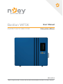
Bason WF5K
ESWMF51H5110BCV01B
User Manual
Manual de ulizare
Before using this product, carefully read all product documentaon and retain it for future reference.
335.11.23.1

Contents
1.Safety Informaon 2
1.1 General Safety 2
1.2 Personal Safety 2
1.3 Electrical Safety 3
1.4 Environment Safety 5
1.5 Transportaon Safety 6
2.Product Informaon 6
2.1 Baery Overview 6
2.2 Appearance 7
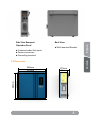
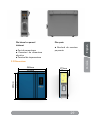
2.3 Dimensions 8
2.4 Capacity Opons 9
2.5 Display 9
2.6 Operaon 11
2.7 Mulple Baeries Parallel Connecon 13
3.Installaon 14
3.1 Unpacking and Inspecon 14
3.2 Tools and Materials 15
3.3 Installaon 16
4.System Commissioning 18
4.1 System Power-On 18
4.2 Baery Informaon Check 19

1
Please read this manual before using the product.
This user manual introduces the energy storage module in terms of
its installaon, electrical connecons, operaon, commissioning,
maintenance, and troubleshoong. Please read through the
manual carefully before installing and using the energy storage
module, and keep the manual well for future reference.
Forward
NOTE!
This user manual is subject to change without prior noce.
Applicaon Model
Bason WF5K
Applicable Personnel
This user manual is intended for photovoltaic (PV) inverter operang
personnel and qualied electrical technicians.

2
English
Română
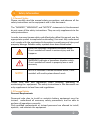
1.1 General Safety
Please carefully read the manual safety precauons, and observe all the
safety instrucons on the equipment and in this document.
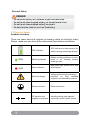
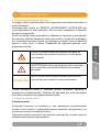
The “DANGER”, “WARNING”, and “NOTICE” statements in this document
do not cover all the safety instrucons. They are only supplements to the
safetyinstrucons.
In order to ensure human safety and eecvely ulize this manual, use the
appropriate symbol to emphased outstanding. You must fully understand
and comply with the emphasized informaon to avoid personal injury and
property damage. Relave safety symbols have been listed below.
1.2 Personal Safety
Personal Requirements
Personnel who plan to install or maintain baery equipment must be
trained, understood all necessary safety precauons, and be able to
perform all operaons correctly.
Only qualied professionals or trained personnel are allowed to install,
operate, and maintain the equipment.
Follow local laws and regulaons when installing, operang, or
maintaining the equipment. The safety instrucons in this document are
only supplements to local laws and regulaons.
DANGER indicates a hazardous situaon which,
if not avoided will result in serious injury and re
happens.
WARNING indicates a hazardous situaon which,
if not avoided will result in property loss or void
warranty
NOTICE indicates a normal situaon which, if not
avoided will result system doesn’t work.
NOTE!
Safety Informaon
1

3
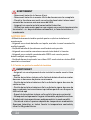
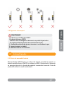
- Do not place battery at a children or pet touchable area.
- Do not touch the energized battery, as the enclosure is hot.
- Do not touch the energized battery terminals.
- Do not stand on, lean on, or sit on the battery.
DANGER
Personal Safety
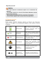
1.3 Electrical Safety
Symbols on baery
There are some electrical symbols on baery relate to electrical safety.
Please make sure you have fully understand them before installaon.
SOC Indicator SOC Indicator on front panel is for
baery energy percentage display
RUN Working indicator
Baery working indicator on front
panel is for showing baery
working status.
ALM Alarm indicator
Red alarm light shows alarm and
fault happen.
Electrical danger
Voltage exits when the baery is
powered on. Only qualied
engineers are allowed to operate.
Earth connector Earth connecon.
DC posive and
negave connectors
Idenfy posive and negave
connectors of DC power source.

4
English
Română
- Before installation, ensure that the equipment is intact.
Otherwise, electric shocks or fire may occur.
- Do not connect or disconnect power cables when battery is
poweron. Which may cause electric arcs and sparks more over fire
or personal injury.
- Before connecting a power cable, check the positive or negative
connectors are correct.
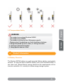
- Do not parallel connect different batteries.
- Do not connect battery with AC directly.
- Do not connect battery with PV wiring directly.
- Do not connect batteries in series.
- Do not connect battery to faulty or unqualified inverter or
charger.
- Do not create short circuits with the external connection.
- Make sure cut-off grid and power-off battery before
maintenance.
- Make sure earth cable connect correctly before operation
DANGER
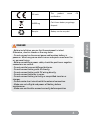
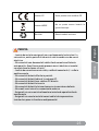
CE mark The product meets CE
cercaon.
WEEE tag Can’t leave baery as garbage
disposal.
Recycle Baery can be recycled

5
1.4 Environment Safety
- Recharge battery every six months.
- Recharge battery within 10 days after battery is fully discharged.
- Please engage greater than or equal to two batteries when
maximum charge current is more than 100A.
- Make sure battery cable placement is installed correctly.
- Use moto meter to make sure there is no voltage between
positive and negative terminals after power-off battery when
install or maintenance.
WARNING
- Ensure that the equipment is installed in a dry and well-ventilated
environment.
- The installation position must be away from direct sunlight and
rain.
- The installation position must be far away from fire sources.
- The installation position must be far away from water sources
such as taps, sewer pipes, and sprinklers to prevent water seepage.
- The bracket must be installed solid and horizontal.
- Do not expose the equipment to flammable or explosive gas or
smoke. Do not perform any operation on the equipment in such
environments.
- The operation and service life of the battery depend on the
operating temperature. Operate the battery at a temperature equal
to or better than the ambient temperature. The recommended
operating temperature ranges from 0°C to 30°C.
WARNING
NOTE!
-Please use dedicated insulated tools for install and maintenance.
- Please make sure all baeries are power-o when mulple parallel
connecon.
- Please check lights on sequence when baery power-on.
- Please make sure communicaon connecon connect correctly with baery
and inverter.
- Please make sure ADDS dip switch sengs are correctly for single or mulple
baeries.
- Please check inverter alarm or SOC reading when there is BMS
communicaon with inverter.

6
English
Română
- The products passed certification UN38.3
- The products have MSDS.
- The products belong to class 9 dangerous goods.
- Please protect the packing case from the below situations.
1. Being dampened by rains, snows, or falling into water
2. Falling or mechanical impact
3. Being upside-down or tilted
WARNING
1.5 Transportaon Safety
Product Informaon
2
2.1 Baery Overview
The Bason WF5K baery is a wall mounted lithium baery pack which
consists of long life-span LiFePO4 baery cells and funconal BMS. It
can store and release electric energy based on the requirements of the
inverter controller. It is mainly for home energy storage system.

7
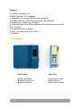
Features
•LiFePO4 prismac cell
• 6000 cycles at 1°C condion
• Maximum 1C charge and discharge capability
• No dip switches, addressing automac self-adapon
• Scalable up to maximum 15 packs
• Protecve and acve BMS allows greater reliability and control
• IP 54 grade
• Connectors built-in design
• Fully recyclable at the end of life
• Compact
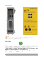
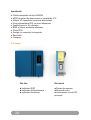
Front View
● SOC indicators
● Working indicator
● Alarm indicator
Side View
● Operaon panel
● Start buon
● DC main breaker
2.2 Appearance


9
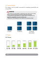
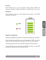
2.4 Capacity Opons
The baery can be parallel connected for extending power(kW) and
energy(kWh)
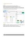
2.5 Display
SOC Display
5.12kWh 10.24kWh 20.48kWh
AND MORE
- The maximum power(kW) is limited by main cables from master
battery to inverter when all batteries are link connected
- The maximum power(kW) can scalable when all batteries are
parallel connected by current combine unit.
- Maximum 15 battery packs can be parallel communicated.
WARNING

10
English
Română
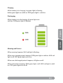
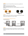
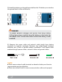
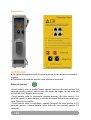
Charging
When baery is in charging, top green light is ashing,
below green lights are solid on. RUN green light is solid on.
Discharging
When baery is in discharging, all green lights are
solid on. RUN green light is ashing.
RUN
ALM
Warning and Protect
When warning happens, ALM red light is ashing.
When over charged protect happens, RUN green light is solid on. ALM red
light is o. SOC green lights are all on.
When over discharged protect happens, all lights are o.
When fail protect happens, RUN green light is o. ALM red light is solid
on. SOC green lights are all o.

11
2.6 Operaon
NOTE!
● Please remove the operaon panel to see the hiding connecons.
● Please operate by qualied engineers.
Start Buon
-When baery is sleeping, push start buon for 3~6 seconds to start
baery, all lights are ashing in turn. Baery is waked up.
-When baery is working, push start buon for 3~6 seconds to sleep
baery, all lights are ashing in turn. Baery is o.
-When baery is working, push start buon for 6~10 seconds to reset
baery, all lights are on for 1.5 seconds.

12
English
Română
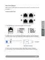
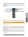
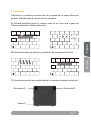
Main Switch (Breaker)
Main switch is a DC breaker to physically to connect or cut o main circuit
of baery.
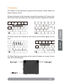
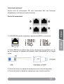
1. CAN/RS485 port is for inverter BMS communicaon.
2. RS232 port is only for debugging through computer engineer soware,
all baery informaon can be read here. The default baud rate is 9600bps.
3. Link in port is the communicaon cable input between baeries.
4. Link out port is the communicaon cable output between baeries.
Communicaon Ports
8

13
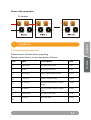
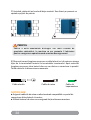
Communicaon Link
NOTE!
● Please be aware the baery BMS protocol need to be compable with
inverter.
● CAN communicaon baud rate is 500K.
● RS232 communicaon baud rate is 9600bps.
● Please communicate with inverter or engineer soware by correct RJ45 Pin
addresses
NOTE!
● Please use the accessory cable kit or connectors for baery power connecon.
● Baery cable suggeson cross-secon 4-6AWG.
NOTE!
● Please know baery addressing is self-adapon, no need dip switch sengs.
● Please use standard network cables and RJ45 heads for link between
baeries.
Power Connectors
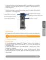
2.7 Mulple Baeries Parallel Connecon

14
English
Română
Power cable connecon
To inverter
Installaon
3
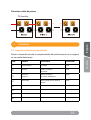
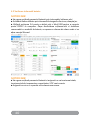
3.1 Unpacking and Inspecon
Please inspect all items when unpacking.
Please ensure there is no any damage for all items.
No. Item Descripon Qty
1Baery Pack 5.12kWh baery pack 1Set
2Bracket Wall mounted bracket 1Set
3Anchor Bolt Wall mounted M8x60mm Bolt 6 PCS
4Cable Plug Power Cable Quick Plug 2 PCS
5RJ 45 Cable For BMS communicaon, 2 meter
length
1 PCS
6QC Report Factory Inspecon Report and QC
card
1 PCS
7Power cables For Power connecon 1 pair
8Earth Lug For earth cable 1 PCS

15
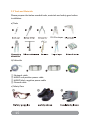
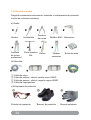
3.2 Tools and Materials
Please prepare the below needed tools, materials and safety gear before
installaon.
a) Tools
① Network cable
② 6AWG red posive power cable
③ 6AWG black negave power cable
④ Ground cable
b) Materials
c) Safety Gear
RJ 45 crimper

16
English
Română
3.3 Installaon
The baery is wall mounted or ground stand directly. Please follow the
below steps for install.
A) Use the bracket as the template to mark the posions of 4 holes, then
drill 12mm holes and make sure the depth of holes is deeper than 60mm.
B) Please mount the bracket on the wall by anchor bolts ghtly on the
wall.
C) Mount bearing accessories on the back of baery by screws. Ensure
they are screwed ghtly.

17
D) Install the baery on the wall mounted bracket. Or baery can stand on
the ground back to the wall directly.
E) Measure the power cable and network cable length from baery
terminals to inverter terminals. Measure the cable length between
baeries too if there is parallel baery installaon. Then please make
moderate length power cables, network cables and ground cables.
To prevent potential damages and injuries from heavy battery
falling down, please carefully hang the battery on the bracket by
two people. Don’t loosen force unless confirm the battery is well
mounted.
DANGER
NOTE!
● Please ensure network cable terminals are based on baery and inverter
communicaon port pin denion.
● Please use network tester to ensure communicaon cable works properly.

18
English
Română
F) Please remove operaon area plate on the right side of baery pack.
And please connect power cables, network cable and ground cable in the
correct ports.
For mulple baeries parallel connecon, please see the content 2.7 in
page 13th.
NOTE!
● Turn on the DC main breaker. Aer the baery is installed and powered on by
start buon for the rst me, all LED blinks for three circles, then LED goes to
normal display.
● Turn o the baery by start buon, SOC and RUN LED blink in turn once,
then goes all o.
● Aer turning on the baery switch, power on the inverter. For details about
how to power on the inverter, see the quick guide for the corresponding
inverter model.
NOTE!
● Please debug baery by engineer soware before recovering operaon plate.
System Commissioning
4
4.1 System Power-On
Pagina se încarcă...
Pagina se încarcă...
Pagina se încarcă...
Pagina se încarcă...
Pagina se încarcă...
Pagina se încarcă...
Pagina se încarcă...
Pagina se încarcă...
Pagina se încarcă...
Pagina se încarcă...
Pagina se încarcă...
Pagina se încarcă...
Pagina se încarcă...
Pagina se încarcă...
Pagina se încarcă...
Pagina se încarcă...
Pagina se încarcă...
Pagina se încarcă...
Pagina se încarcă...
Pagina se încarcă...
Pagina se încarcă...
Pagina se încarcă...
Pagina se încarcă...
Pagina se încarcă...
-
 1
1
-
 2
2
-
 3
3
-
 4
4
-
 5
5
-
 6
6
-
 7
7
-
 8
8
-
 9
9
-
 10
10
-
 11
11
-
 12
12
-
 13
13
-
 14
14
-
 15
15
-
 16
16
-
 17
17
-
 18
18
-
 19
19
-
 20
20
-
 21
21
-
 22
22
-
 23
23
-
 24
24
-
 25
25
-
 26
26
-
 27
27
-
 28
28
-
 29
29
-
 30
30
-
 31
31
-
 32
32
-
 33
33
-
 34
34
-
 35
35
-
 36
36
-
 37
37
-
 38
38
-
 39
39
-
 40
40
-
 41
41
-
 42
42
-
 43
43
-
 44
44


în alte limbi
- English: Njoy WF5K User manual
Lucrări înrudite
Alte documente
-
Victron energy MultiPlus-II 12 3000 120-32 Manual de utilizare
-
Goodwe GW5KL-ET Ghid de instalare
-
Rebel URZ3163 Manual de utilizare
-
Rebel URZ3164-65 Manual de utilizare
-
 Inventor U4MRS-12B Manual de utilizare
-
Eaton CEAG ZB-S Mounting And Operating Instructions
-
Akai CT 2109 Manual de utilizare
-
Allview TV 32ATC5000-H-SB Manual de utilizare
