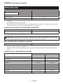
Makita DUX18 Manual de utilizare
- Categorie
- Unelte electrice
- Tip
- Manual de utilizare

DUX18
EN Cordless Multi Function
Power Head INSTRUCTION MANUAL 6
PL Bezprzewodowa
Wielofunkcyjna Jednostka
Napędowa INSTRUKCJA OBSŁUGI 16
HU Vezeték nélküli többfunkciós
alapgép HASZNÁLATI KÉZIKÖNYV 28
SK Akumulátorová multifunkčná
motorová jednotka NÁVOD NA OBSLUHU 39
CS Akumulátorová multifunkční
motorová jednotka NÁVOD K OBSLUZE 50
UK Акумуляторний
багатофункціональний
приводний інструмент
ІНСТРУКЦІЯ З
ЕКСПЛУАТАЦІЇ 61
RO Cap cu motor universal fără
cablu MANUAL DE INSTRUCŢIUNI 73
DE Multifunktions-Antrieb BETRIEBSANLEITUNG 84

Fig.1
Fig.2
12 1
2
3
4
5
11
10
9
8
Fig.3
2
1
8
3
4
7
10
5
6
8
9
Fig.4
2

2
1
3
Fig.5
1
Fig.6
1
2
Fig.7
1
2
Fig.8
2
1
Fig.9
1
2
Fig.10
3
2
1
1
5
4
Fig.11
1
2
Fig.12
3

1
Fig.13
1
2
3
Fig.14
1
Fig.15
Fig.12
3
1
2
Fig.16
1
2
Fig.17
Fig.18
1
2
Fig.19
Fig.20
4

1
Fig.21
1
2
Fig.22
1
Fig.23
5

6ENGLISH
ENGLISH (Original instructions)
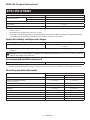
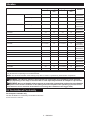
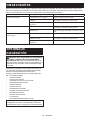
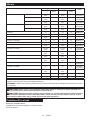
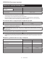
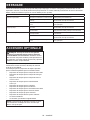
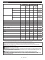
SPECIFICATIONS
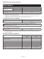
Model: DUX18
No load speed
(without attachment) Low 0 - 6,800 min-1
High 0 - 9,700 min-1
Overall length 977 mm
Rated voltage D.C. 18 V
Net weight 4.0 kg - 10.3 kg
• Due to our continuing program of research and development, the specications herein are subject to change
without notice.
• Specications may dier from country to country.
• The weight may dier depending on the attachment(s), including the battery cartridge. The lightest and heavi-
est combination, according to EPTA-Procedure 01/2014, are shown in the table.
Applicable battery cartridge and charger
Battery cartridge BL1820B /BL1830B /BL1840B /BL1850B /BL1860B
Charger DC18RC /DC18RD /DC18RE /DC18SD /DC18SE /DC18SF /
DC18SH
• Some of the battery cartridges and chargers listed above may not be available depending on your region of
residence.
WARNING: Only use the battery cartridges and chargers listed above. Use of any other battery cartridges
and chargers may cause injury and/or re.
Recommended portable power pack
Portable power pack PDC01
• The portable power pack(s) listed above may not be available depending on your region of residence.
• Before using the portable power pack, read instruction and cautionary markings on the portable power pack.
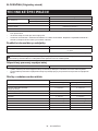
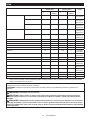
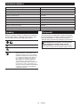
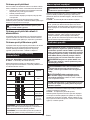
No load speed with attachment
Model Rotation speed
Low High
EM408MP, EM409MP 0-5,000 min-1 0 - 7,000 min-1
EN401MP, EN410MP, EN420MP
(Strokes per minute) 0-2,800 min-1 0 - 4,000 min-1
EY401MP (chain speed) 0-14 m/s 0-20 m/s
KR400MP 0-200 min-1 0-280 min-1
KR401MP 0 - 160 min-1 0-230 min-1
EE400MP 0 - 3,300 min-1 0 - 4,700 min-1
EJ400MP 0-2,000 min-1 0-2,800 min-1
BR400MP 0 - 160 min-1 0-230 min-1
SW400MP 0 - 160 min-1 0-230 min-1
UB400MP 0 - 6,100 min-1 0 - 6,700 min-1

7ENGLISH
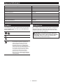
Approved attachment
Type Model
Grass trimmer attachment EM408MP, EM409MP
Hedge trimmer attachment EN401MP, EN410MP
Ground trimmer attachment EN420MP
Pole saw attachment EY401MP
Cultivator attachment KR400MP, KR401MP
Edger attachment EE400MP
Coee harvester attachment EJ400MP
Shaft extension attachment LE400MP
Power brush attachment BR400MP
Power sweep attachment SW400MP
Blower attachment UB400MP
Symbols
The followings show the symbols which may be used
for the equipment. Be sure that you understand their
meaning before use.
Read instruction manual.
Take particular care and attention.
Do not expose to moisture.
Ni-MH
Li-ion Only for EU countries
Do not dispose of electric equipment or
battery pack together with household
waste material! In observance of the
European Directives, on Waste Electric
and Electronic Equipment and Batteries
and Accumulators and Waste Batteries and
Accumulators and their implementation
in accordance with national laws, electric
equipment and batteries and battery
pack(s) that have reached the end of
their life must be collected separately and
returned to an environmentally compatible
recycling facility.
Intended use
This cordless multi function power head is intended for
driving an approved attachment listed in the section
"SPECIFICATIONS" of this instruction manual. Never
use the unit for the other purpose.
WARNING: Read the instruction manual of
the attachment as well as this instruction manual
before using. Failure to follow the warnings and
instructions may result serious injury.

8ENGLISH
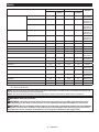
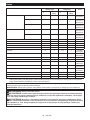
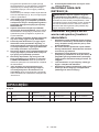
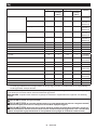
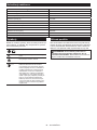
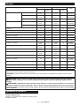
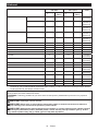
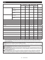
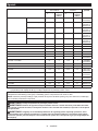
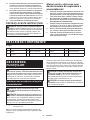
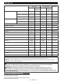
Noise
Attachment
Sound pressure level average Sound power level average
Applicable
standard
LPA (dB (A))
Uncertainty K
(dB (A))
LWA (dB (A))
Uncertainty
K (dB (A))
EM408MP Metal blade 78.7 1.2 94.0 2.3
ISO22868
(ISO11806-1)
Nylon cutting head 77.7 1.7 91.7 1.2
ISO22868
(ISO11806-1)/
EN50636-2-91
Plastic blade 79.3 1.0 90.5 1.3
ISO22868
(ISO11806-1)/
EN50636-2-91
EM409MP Nylon cutting head 78.2 2.1 92.4 1.2
ISO22868
(ISO11806-1)/
EN50636-2-91
Plastic blade 79.8 0.8 91.0 2.0
ISO22868
(ISO11806-1)/
EN50636-2-91
EN401MP 83 394 3
EN62841-4-2
EN401MP +LE400MP 84 395 3
EN62841-4-2
EN410MP 81 392 3
EN62841-4-2
EN410MP +LE400MP 79 390 3
EN62841-4-2
EN420MP 82 393 3
EN62841-4-2
EY401MP 87 3102 3
ISO22868
(ISO11680-1)
EY401MP +LE400MP 87 3102 3
ISO22868
(ISO11680-1)
KR400MP 73.0 3.2 83.4 2.7 EN709
KR401MP 73.6 3.8 83.2 2.9 EN709
EE400MP 73.8 1.4 86.8 3.3 ISO11789 /
2000/14/EC
EJ400MP 80.7 0.7 91.4 1.2
ISO22868
(ISO11806-1)
EJ400MP +LE400MP 78.1 0.9 91.3 0.6
ISO22868
(ISO11806-1)
BR400MP 76.0 1.3 86.8 1.2
EN60335-2-72
SW400MP 76.2 0.2 85.8 0.7
EN60335-2-72
UB400MP 85.3 1.7 99.5 1.2
EN50636-2-100
• Even if the sound pressure level listed above is 80 dB (A) or less, the level under working may exceed 80 dB
(A). Wear ear protection.
NOTE: The declared noise emission value(s) has been measured in accordance with astandard test method and
may be used for comparing one tool with another.
NOTE: The declared noise emission value(s) may also be used in apreliminary assessment of exposure.
WARNING: Wear ear protection.
WARNING: The noise emission during actual use of the power tool can dier from the declared val-
ue(s) depending on the ways in which the tool is used especially what kind of workpiece is processed.
WARNING: Be sure to identify safety measures to protect the operator that are based on an estimation
of exposure in the actual conditions of use (taking account of all parts of the operating cycle such as the
times when the tool is switched o and when it is running idle in addition to the trigger time).

9ENGLISH
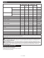
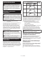
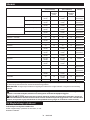
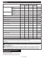
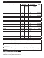
Vibration
Attachment Left handle (Front grip) Right handle (Rear grip) Applicable
standard
ah (m/s2)
Uncertainty K
(m/s2)
ah (m/s2)
Uncertainty K
(m/s2)
EM408MP Metal blade 2.5 or less 1.5 2.5 or less 1.5
ISO22867
(ISO11806-1)
Nylon cutting head 2.5 or less 1.5 2.5 or less 1.5
ISO22867
(ISO11806-1)
Plastic blade 2.5 or less 1.5 2.5 or less 1.5
ISO22867
(ISO11806-1)
EM409MP Nylon cutting head 2.5 or less 1.5 2.5 or less 1.5
ISO22867
(ISO11806-1)
Plastic blade 2.5 or less 1.5 2.5 or less 1.5
ISO22867
(ISO11806-1)
EN401MP 3.1 1.5 3.5 1.5
EN62841-4-2
EN401MP +LE400MP 5.5 1.5 3.8 1.5
EN62841-4-2
EN410MP 2.5 or less 1.5 2.9 1.5
EN62841-4-2
EN410MP +LE400MP 4.3 1.5 3.7 1.5
EN62841-4-2
EN420MP 2.9 1.5 3.0 1.5
EN62841-4-2
EY401MP 2.5 or less 1.5 2.5 or less 1.5
ISO22867
(ISO11680-1)
EY401MP +LE400MP 2.5 or less 1.5 2.5 or less 1.5
ISO22867
(ISO11680-1)
KR400MP 2.5 or less 1.5 2.5 or less 1.5 EN709
KR401MP 2.5 or less 1.5 2.5 or less 1.5 EN709
EE400MP 2.5 or less 1.5 2.5 or less 1.5 ISO11789
EJ400MP 3.4 1.9 5.0 1.9
ISO22867
(ISO11806-1)
EJ400MP +LE400MP 4.6 1.5 3.2 1.5
ISO22867
(ISO11806-1)
BR400MP 2.5 or less 1.5 2.5 or less 1.5
EN60335-2-72
SW400MP 2.6 1.5 2.5 or less 1.5
EN60335-2-72
UB400MP 4.2 2.2 2.8 1.2
EN50636-2-100
NOTE: The declared vibration total value(s) has been measured in accordance with astandard test method and
may be used for comparing one tool with another.
NOTE: The declared vibration total value(s) may also be used in apreliminary assessment of exposure.
WARNING: The vibration emission during actual use of the power tool can dier from the declared
value(s) depending on the ways in which the tool is used especially what kind of workpiece is processed.
WARNING: Be sure to identify safety measures to protect the operator that are based on an estimation
of exposure in the actual conditions of use (taking account of all parts of the operating cycle such as the
times when the tool is switched o and when it is running idle in addition to the trigger time).
EC Declaration of Conformity
For European countries only
The EC declaration of conformity is included as Annex A
to this instruction manual.

10 ENGLISH
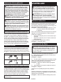
SAFETY WARNINGS
General power tool safety warnings
WARNING: Read all safety warnings, instruc-
tions, illustrations and specications provided
with this power tool. Failure to follow all instructions
listed below may result in electric shock, re and/or
serious injury.
Save all warnings and instruc-
tions for future reference.
The term "power tool" in the warnings refers to your
mains-operated (corded) power tool or battery-operated
(cordless) power tool.
Additional safety instructions
1. Always keep your hands, face, and clothes
away from the cutting tool when it is rotating.
Failure to do so may cause personal injury.
2. During operation, keep bystanders or animals
at least 15 m away from the tool. Stop the tool
as soon as someone approaches.
3. During operation, never stand on an unstable
or slippery surface or a steep slope. During
the cold season, beware of ice and snow and
always ensure secure footing.
4. Never work on a ladder or tree to avoid loss of
control.
5. Before operation, examine the work area for
stones or other solid objects. They can be
thrown or cause dangerous kickback and result in
serious injury and/or property damage.
6. When using cutting blades, avoid kickback
and always prepare for an accidental kickback.
See the section for Kickback.
7. When you leave the tool, even if it is a short
time, always remove the battery cartridge. The
unattended tool with the battery cartridge installed
may be used by unauthorized person and cause
serious accident.
8. Before doing any maintenance or repair work
or cleaning the tool, always turn it o and
remove the battery cartridge.
9. Before storing the tool, perform full cleaning
and maintenance. Remove the battery car-
tridge. Attach the cover to the cutting blade.
10. Store the tool in a dry and high or locked loca-
tion out of reach of children.
11. When touching the cutting blade, wear protec-
tive gloves. Cutting blades can cut bare hands
severely.
12. When handling a cutter blade, always wear
gloves and put the blade cover on the blade.
13. When not in use, attach the blade cover onto
the blade. Remove the cover before operation.
14. Before transporting the tool, turn it o and
remove the battery cartridge. Attach the cover
to the cutting blade.
15. Before starting the tool, be sure that the cut-
ting tool is not touching the ground and other
obstacles such as a tree.
16. The cutting tool has to be equipped with the
guard. Never run the tool with damaged guards
or without guards in place!
17. Check the cutting attachment frequently
during operation for cracks or damages.
Before the inspection, remove the battery
cartridge and wait until the cutting attachment
stops completely. Replace damaged cutting
attachment immediately, even if it has only
supercial cracks.
18. Do not operate the tool in bad weather or if
there is a risk of lightning.
19. Make sure there are no electrical cables, water
pipes, gas pipes etc. that could cause a hazard
if damaged by use of the tool.
20. During operation always hold the tool with
both hands. Never hold the tool with one hand
during use.
21. Keep handles dry, clean and free from oil and
grease. Keep all cooling air inlets clear of
debris.
22. During operation, use the shoulder harness.
Keep the tool on your right side rmly.
23. Do not touch the gear case during and imme-
diately after the operation. The gear case
becomes hot during operation and can cause burn
injury.
24. Take a rest to prevent loss of control caused
by fatigue. We recommend taking a10 to 20-min-
ute rest every hour.
25. Avoid dangerous environment. Don't use the
tool in dump or wet locations or expose it to
rain. Water entering the tool will increase the risk
of electric shock.
26. Do not dispose of the battery(ies) in a re.
The cell may explode. Check with local codes for
possible special disposal instructions.
27. Do not open or mutilate the battery(ies).
Released electrolyte is corrosive and may cause
damage to the eyes or skin. It may be toxic if
swallowed.
28. Do not charge battery in rain, or in wet
locations.
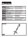
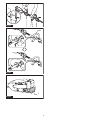
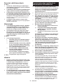
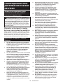
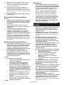
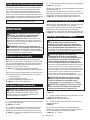
Personal protective equipment
►Fig.1
1. Wear safety helmet, protective goggles and
protective gloves to protect yourself from
ying debris or falling objects.
2. Wear ear protection such as ear mus to pre-
vent hearing loss.
3. Wear proper clothing and shoes for safe
operation, such as a work overall and sturdy,
non-slip shoes. Do not wear loose clothing or
jewelry. Loose clothes, jewelry or long hair can be
caught in moving parts.
4. When touching the cutting blade, wear protec-
tive gloves. Cutting blades can cut bare hands
severely.

11 ENGLISH
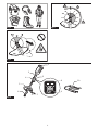
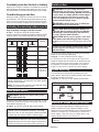
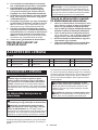
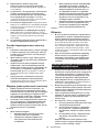
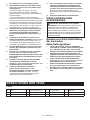
Kickback (Blade thrust)
1. Kickback (blade thrust) is a sudden reaction
to a caught or bound cutting blade. Once it
occurs, the tool is thrown sideway or toward
the operator at great force and it may cause
serious injury.
2. Kickback occurs particularly when applying
the blade segment between 12 and 2 o'clock
to solids, bushes and trees with 3 cm or larger
diameter.
►Fig.2
3. To avoid kickback:
1. Apply the segment between 8 and 11
o'clock.
2. Never apply the segment between 12 and
2 o'clock.
3. Never apply the segment between 11 and
12 o'clock and between 2 and 5 o'clock,
unless the operator is well trained and
experienced and does it at his/her own
risk.
4. Never use cutting blades close to solids,
such as fences, walls, tree trunks and
stones.
5. Never use cutting blades vertically, for
such operations as edging and trimming
hedges.
►Fig.3
Vibration
1. People with poor circulation who are exposed
to excessive vibration may experience injury
to blood vessels or the nervous system.
Vibration may cause the following symptoms
to occur in the ngers, hands or wrists: "Falling
asleep" (numbness), tingling, pain, stabbing sen-
sation, alteration of skin color or of the skin. If any
of these symptoms occur, see aphysician!
2. To reduce the risk of "white nger disease",
keep your hands warm during operation and
well maintain the tool and accessories.
Important safety instructions for
battery cartridge
1. Before using battery cartridge, read all instruc-
tions and cautionary markings on (1) battery
charger, (2) battery, and (3) product using
battery.
2. Do not disassemble or tamper with the battery
cartridge. It may result in are, excessive heat,
or explosion.
3. If operating time has become excessively
shorter, stop operating immediately. It may
result in a risk of overheating, possible burns
and even an explosion.
4. If electrolyte gets into your eyes, rinse them
out with clear water and seek medical atten-
tion right away. It may result in loss of your
eyesight.
5. Do not short the battery cartridge:
(1) Do not touch the terminals with any con-
ductive material.
(2) Avoid storing battery cartridge in a con-
tainer with other metal objects such as
nails, coins, etc.
(3) Do not expose battery cartridge to water
or rain.
A battery short can cause a large current ow, over-
heating, possible burns and even a breakdown.
6. Do not store and use the tool and battery car-
tridge in locations where the temperature may
reach or exceed 50 °C (122 °F).
7. Do not incinerate the battery cartridge even if
it is severely damaged or is completely worn
out. The battery cartridge can explode in a re.
8. Do not nail, cut, crush, throw, drop the battery
cartridge, or hit against a hard object to the
battery cartridge. Such conduct may result in a
re, excessive heat, or explosion.
9. Do not use a damaged battery.
10.
The contained lithium-ion batteries are subject to
the Dangerous Goods Legislation requirements.
For commercial transports e.g. by third parties,
forwarding agents, special requirement on pack-
aging and labeling must be observed.
For preparation of the item being shipped, consult-
ing an expert for hazardous material is required.
Please also observe possibly more detailed
national regulations.
Tape or mask o open contacts and pack up the
battery in such amanner that it cannot move
around in the packaging.
11. When disposing the battery cartridge, remove
it from the tool and dispose of it in a safe
place. Follow your local regulations relating to
disposal of battery.
12. Use the batteries only with the products
specied by Makita. Installing the batteries to
non-compliant products may result in are, exces-
sive heat, explosion, or leak of electrolyte.
13. If the tool is not used for a long period of time,
the battery must be removed from the tool.
14. During and after use, the battery cartridge may
take on heat which can cause burns or low
temperature burns. Pay attention to the han-
dling of hot battery cartridges.
15.
Do not touch the terminal of the tool immediately
after use as it may get hot enough to cause burns.
16. Do not allow chips, dust, or soil stuck into the
terminals, holes, and grooves of the battery
cartridge. It may result in poor performance or
breakdown of the tool or battery cartridge.
17. Unless the tool supports the use near
high-voltage electrical power lines, do not use
the battery cartridge near high-voltage electri-
cal power lines. It may result in amalfunction or
breakdown of the tool or battery cartridge.
18. Keep the battery away from children.
SAVE THESE INSTRUCTIONS.
CAUTION: Only use genuine Makita batteries.
Use of non-genuine Makita batteries, or batteries that
have been altered, may result in the battery bursting
causing res, personal injury and damage. It will
also void the Makita warranty for the Makita tool and
charger.

12 ENGLISH
Tips for maintaining maximum
battery life
1.
Charge the battery cartridge before completely dis-
charged. Always stop tool operation and charge the
battery cartridge when you notice less tool power.
2. Never recharge a fully charged battery car-
tridge. Overcharging shortens the battery
service life.
3. Charge the battery cartridge with room tem-
perature at 10 °C - 40 °C (50 °F - 104 °F). Let
a hot battery cartridge cool down before
charging it.
4. When not using the battery cartridge, remove
it from the tool or the charger.
5. Charge the battery cartridge if you do not use
it for a long period (more than six months).
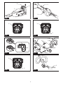
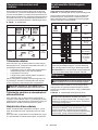
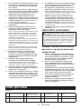
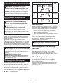
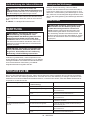
PARTS DESCRIPTION
►Fig.4
1Battery cartridge 2Lock-o lever 3Switch trigger 4Hanger
5Handle 6Release button 7Barrier 8Indicator lamps
9Main power button 10 Shoulder harness ----
FUNCTIONAL
DESCRIPTION
WARNING: Always be sure that the tool is
switched o and the battery cartridge is removed
before adjusting or checking function on the tool.
Failure to switch o and remove the battery cartridge
may result in serious personal injury from accidental
start-up.
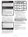
Installing or removing battery
cartridge
CAUTION: Always switch o the tool before
installing or removing of the battery cartridge.
CAUTION: Hold the tool and the battery car-
tridge rmly when installing or removing battery
cartridge. Failure to hold the tool and the battery
cartridge rmly may cause them to slip o your hands
and result in damage to the tool and battery cartridge
and apersonal injury.
►Fig.5: 1. Red indicator 2. Button 3. Battery cartridge
To remove the battery cartridge, slide it from the tool
while sliding the button on the front of the cartridge.
To install the battery cartridge, align the tongue on the
battery cartridge with the groove in the housing and slip
it into place. Insert it all the way until it locks in place
with alittle click. If you can see the red indicator on the
upper side of the button, it is not locked completely.
CAUTION: Always install the battery cartridge
fully until the red indicator cannot be seen. If not,
it may accidentally fall out of the tool, causing injury to
you or someone around you.
CAUTION: Do not install the battery cartridge
forcibly. If the cartridge does not slide in easily, it is
not being inserted correctly.
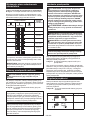
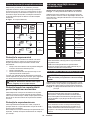
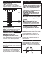
Tool / battery protection system
The tool is equipped with atool/battery protection system.
This system automatically cuts o power to the motor to
extend tool and battery life. The tool will automatically
stop during operation and the indicator lamps light up if
the tool is placed under one of the following conditions:
►Fig.6: 1. Indicator lamps
Indicator lamps Protection
status
Color
Lighted O Blinking
Green Overload
Red Overheat
Red Over-
discharge
Overload protection
If the tool or battery gets into one of the following situa-
tion, the tool automatically stops and the indicator lamp
starts blinking in green:
— The tool or battery is overloaded by entangled
weeds or other debris.
—The tool is locked.
— The main power button is turned on while the
switch trigger is being pulled.
In this situation, release the switch trigger and remove
the cause of overload if necessary. After that, pull the
switch trigger again to resume.
CAUTION: Before you remove the cause of
overload, be sure to turn the tool o.

13 ENGLISH
Overheat protection for tool or battery
When the tool or battery cartridge is overheated, the tool stops
automatically and the indicator lamp lights up in red. Let the
tool and/or battery cool down before turning the tool on again.
Overdischarge protection
When the battery capacity becomes low, the tool stops
automatically. The indicator lamp starts blinking in red.
If the tool does not operate even when the switches are oper-
ated, remove the battery cartridge from the tool and charge it.
Indicating the remaining battery capacity
Only for battery cartridges with the indicator
►Fig.7: 1. Indicator lamps 2. Check button
Press the check button on the battery cartridge to indicate the remain-
ing battery capacity. The indicator lamps light up for afew seconds.
Indicator lamps Remaining
capacity
Lighted O Blinking
75% to 100%
50% to 75%
25% to 50%
0% to 25%
Charge the
battery.
The battery
may have
malfunctioned.
NOTE: Depending on the conditions of use and the
ambient temperature, the indication may dier slightly
from the actual capacity.
NOTE: The rst (far left) indicator lamp will blink when
the battery protection system works.
Main power switch
WARNING: Always turn o the main power
switch when not in use.
Press the main power button to turn on the tool. To turn
o the tool, press and hold the main power button until
the indicator lamps go o.
►Fig.8: 1. Indicator lamps 2. Main power button
NOTE: The indicator lamp brinks if the switch trigger
is pulled under unoperatable conditions. The lamp
blinks if you turn on the main power switch while hold-
ing down the lock-o lever and the switch trigger.
NOTE:
This tool employs the auto power-o function. To
avoid unintentional start up, the main power switch will auto-
matically shut down when the switch trigger is not pulled for
a certain period after the main power switch is turned on.
Switch action
WARNING: For your safety, this tool is
equipped with lock-o lever which prevents the
tool from unintended starting. NEVER use the tool
if it runs when you simply pull the switch trigger
without pressing the lock-o lever. Return the
tool to our authorized service center for proper
repairs BEFORE further usage.
WARNING: NEVER tape down or defeat pur-
pose and function of lock-o lever.
CAUTION: Before installing the battery car-
tridge into the tool, always check to see that the
switch trigger actuates properly and returns to
the "OFF" position when released.
CAUTION: Never put your nger on the main
power button and switch trigger when carrying
the tool. The tool may start unintentionally and cause
injury.
NOTICE: Do not pull the switch trigger hard with-
out pressing the lock-o lever. This can cause
switch breakage.
To prevent the switch trigger from being accidentally
pulled, alock-o lever is provided.
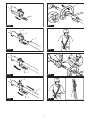
►Fig.9: 1. Lock-o lever 2. Switch trigger
To start the tool, turn on the main power switch and
grasp the handle (the lock-o lever is released by the
grasp) and then pull the switch trigger. Tool speed is
increased by increasing the pressure on the switch
trigger. To stop the tool, release the switch trigger.
Speed adjusting
You can select the tool speed by tapping the main
power button. Each time you tap the main power button,
the level of speed will change.
►Fig.10: 1. Indicator lamps 2. Main power button
Indicator lamps Mode
High
Low
Electronic torque control function
The tool electronically detects asudden drop in the
rotation speed which may cause akickback. In this
situation, the tool automatically stops to prevent further
rotation of cutting tool. To restart the tool, release the
switch trigger. Clear the cause of sudden drop in the
rotation speed and then turn the tool on.
NOTE: This function is not a preventive measure for
kickbacks.

14 ENGLISH
ASSEMBLY
WARNING: Always be sure that the tool is
switched o and battery cartridge is removed
before carrying out any work on the tool. Failure to
switch o and remove the battery cartridge may result
in serious personal injury from accidental start-up.
WARNING: Never start the tool unless it is
completely assembled. Operation of the tool in a
partially assembled state may result in serious per-
sonal injury from accidental start-up.
Mounting the handle
Attach the handle with supplied clamps and bolts. Make
sure that the handle is located between the spacer and
the arrow mark. Do not remove or shrink the spacer.
►Fig.11: 1. Clamp 2. Hex socket bolt 3. Handle
4. Arrow mark 5. Spacer
When using the following attachments, be sure to attach
the barrier to the handle using the screw on the barrier.
•Grass trimmer attachment *
• Edger attachment
*. Only when metal blade is attached.
►Fig.12: 1. Barrier 2. Screw
Mounting the attachment pipe
CAUTION: Always check that the attachment
pipe is secured after installation. Improper instal-
lation may cause the attachment falling o from the
power unit and cause personal injury.
Mount the attachment pipe to the power unit.
1. Turn the lever of the power unit toward the attach-
ment side.
►Fig.13: 1. Lever
2. Remove the cap of the attachment. Align the pin
with the arrow mark and insert the attachment pipe until
the release button pops up.
►Fig.14: 1. Release button 2. Arrow mark 3. Pin
3. Turn the lever toward the power unit side.
►Fig.15: 1. Lever
Make sure that the surface of the lever is parallel to the
pipe.
To remove the pipe, turn the lever toward the attach-
ment side and pull the pipe out while pressing down the
release button.
►Fig.16: 1. Release button 2. Lever 3. Pipe
Adjusting the handle position
Adjust the handle position to obtain comfortable han-
dling of the tool.
Loosen the hex socket head bolt on the handle. Move
the handle to acomfortable working position and then
tighten the bolt.
►Fig.17: 1. Handle 2. Hex socket head bolt
Attaching the shoulder harness
WARNING: Be extremely careful to maintain
control of the tool at all times. Do not allow the
tool to be deected toward you or anyone in the
work vicinity. Failure to keep control of the tool
could result in serious injury to the bystander and the
operator.
CAUTION: When you use the tool in combi-
nation of the backpack-type power supply such
as portable power pack, do not use the shoulder
harness included in the tool package, but use the
hanging band recommended by Makita.
If you put on the shoulder harness included in the
tool package and the shoulder harness of the back-
pack-type power supply at the same time, removing
the tool or backpack-type power supply is dicult in
case of an emergency, and it may cause an accident
or injury. For the recommended hanging band, ask
Makita Authorized Service Centers.
CAUTION: Always use the shoulder harness
attached to the tool. Before operation, adjust the
shoulder harness according to the user size to
prevent fatigue.
CAUTION: Before operation, make sure that
the shoulder harness is properly attached to the
hanger on the tool.
1. Wear the shoulder harness on your left shoulder.
►Fig.18
2. Clasp the hook on the shoulder strap to tool's
hanger.
►Fig.19: 1. Hanger 2. Hook
3. Adjust the shoulder harness to acomfortable
working position.
►Fig.20
The shoulder harness features a means of quick
release.
Simply squeeze the sides of the buckle to release the
tool from the shoulder harness.
►Fig.21: 1. Buckle
Hex wrench storage
CAUTION: Be careful not to leave the hex
wrench inserted in the tool head. It may cause
injury and/or damage to the tool.
When not in use, store the hex wrench as illustrated to
keep it from being lost.
►Fig.22: 1. Handle 2. Hex wrench

15 ENGLISH
MAINTENANCE
WARNING: Always be sure that the tool is
switched o and battery cartridge is removed
before attempting to perform inspection or main-
tenance on the tool. Failure to switch o and remove
the battery cartridge may result in serious personal
injury from accidental start-up.
NOTICE: Never use gasoline, benzine, thinner,
alcohol or the like. Discoloration, deformation or
cracks may result.
To maintain product SAFETY and RELIABILITY,
repairs, any other maintenance or adjustment should
be performed by Makita Authorized or Factory Service
Centers, always using Makita replacement parts.
Cleaning the tool
Clean the tool by wiping o dust, dirt, or cut o grass
with adry cloth or one dipped in soapy water and wrung
out. To avoid overheating of the tool, be sure to remove
the cut o grass or debris adhered to the vent of the
tool.
Battery guard
WARNING: Do not remove the battery
guard. Do not use the tool with the battery guard
removed or damaged. Direct impact to the battery
cartridge may cause battery malfunction and result
in injury and/or re. If the battery guard is deformed
or damaged, contact your authorized service center
for repairs.
►Fig.23: 1. Battery guard
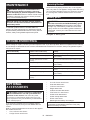
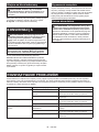
TROUBLESHOOTING
Before asking for repairs, conduct your own inspection rst. If you nd aproblem that is not explained in the manual,
do not attempt to dismantle the tool. Instead, ask Makita Authorized Service Centers, always using Makita replace-
ment parts for repairs.
State of abnormality Probable cause (malfunction) Remedy
Motor does not run. Battery cartridge is not installed. Install the battery cartridge.
Battery problem (under voltage) Recharge the battery. If recharging is not eective,
replace battery.
The drive system does not work
correctly.
Ask your local authorized service center for repair.
Motor stops running after alittle use. Battery's charge level is low. Recharge the battery. If recharging is not eective,
replace battery.
Overheating. Stop using of tool to allow it to cool down.
It does not reach maximum RPM. Battery is installed improperly. Install the battery cartridge as described in this
manual.
Battery power is dropping. Recharge the battery. If recharging is not eective,
replace battery.
The drive system does not work
correctly.
Ask your local authorized service center for repair.
OPTIONAL
ACCESSORIES
CAUTION: These accessories or attachments
are recommended for use with your Makita tool
specied in this manual. The use of any other
accessories or attachments might present a risk of
injury to persons. Only use accessory or attachment
for its stated purpose.
If you need any assistance for more details regard-
ing these accessories, ask your local Makita Service
Center.
Refer to "Approved attachment" section for the applica-
ble models for this tool.
•Grass trimmer attachment
•Hedge trimmer attachment
•Ground trimmer attachment
• Pole saw attachment
•Cultivator attachment
• Edger attachment
• Coee harvester attachment
•Shaft extension attachment
• Power brush attachment
• Power sweep attachment
•Blower attachment
• Makita genuine battery and charger
NOTE: Some items in the list may be included in the
tool package as standard accessories. They may
dier from country to country.

16 POLSKI
POLSKI (Instrukcja oryginalna)
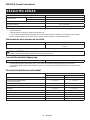
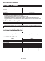
DANE TECHNICZNE
Model: DUX18
Prędkość bez obciążenia
(bez przyrządu) Niska 0 - 6 800 min-1
Wysoka 0 - 9 700 min-1
Długość całkowita 977 mm
Napięcie znamionowe Prąd stały 18 V
Masa netto 4,0 kg - 10,3 kg
• W związku ze stale prowadzonym przez naszą rmę programem badawczo-rozwojowym niniejsze dane mogą
ulec zmianom bez wcześniejszego powiadomienia.
• Dane techniczne mogą różnić się wzależności od kraju.
• Masa może być różna wzależności od osprzętu, wtym akumulatora. Wtabeli przedstawiona jest najlżejsza i
najcięższa konguracja, zgodnie zprocedurą EPTA 01/2014.
Kompatybilne akumulatory i ładowarki
Akumulator BL1820B /BL1830B /BL1840B /BL1850B /BL1860B
Ładowarka DC18RC /DC18RD /DC18RE /DC18SD /DC18SE /DC18SF /
DC18SH
• Pewne zwymienionych powyżej akumulatorów iładowarek mogą być niedostępne wregionie zamieszkania
użytkownika.
OSTRZEŻENIE: Należy używać wyłącznie akumulatorów i ładowarek wymienionych powyżej.
Używanie innych akumulatorów iładowarek może stwarzać ryzyko wystąpienia obrażeń ciała lub pożaru.
Zalecana przenośna jednostka zasilająca
Przenośna jednostka zasilająca PDC01
• Wymieniona powyżej przenośna jednostka zasilająca może być niedostępna wregionie zamieszkania
użytkownika.
• Przed użyciem przenośnej jednostki zasilającej należy przeczytać instrukcję oraz ostrzeżenia umieszczone na
jednostce.
Prędkość bez obciążenia z przyrządem
Model Prędkość obrotowa
Niska Wysoka
EM408MP, EM409MP 0–5 000 min-1 0–7 000 min-1
EN401MP, EN410MP, EN420MP
(Liczba oscylacji na minutę)
0–2 800 min-1 0–4 000 min-1
EY401MP (prędkość łańcucha) 0–14 m/s 0–20 m/s
KR400MP 0–200 min-1 0–280 min-1
KR401MP 0–160 min-1 0–230 min-1
EE400MP 0–3 300 min-1 0–4 700 min-1
EJ400MP 0–2 000 min-1 0–2 800 min-1
BR400MP 0–160 min-1 0–230 min-1
SW400MP 0–160 min-1 0–230 min-1
UB400MP 0–6 100 min-1 0–6 700 min-1

17 POLSKI
Przyrząd zatwierdzony
Typ Model
Wykaszarka —przystawka EM408MP, EM409MP
Przyrząd Do Cięcia Żywopłotu EN401MP, EN410MP
Przystawka —Nożyce do Żywopłotu EN420MP
Przyrząd Do Podcinania Gałęzi EY401MP
Przyrząd Do Spulchniania Gleby KR400MP, KR401MP
Przystawka —Krawędziarka EE400MP
Przyrząd Do Zbioru Kawy EJ400MP
Przedłużenie Wału LE400MP
Szczotka Obrotowa BR400MP
Zamiatarka SW400MP
Przystawka dmuchawy UB400MP
Symbole
Poniżej pokazano symbole, jakie mogą być zastoso-
wane na urządzeniu. Przed rozpoczęciem użytkowania
należy zapoznać się zich znaczeniem.
Przeczytać instrukcję obsługi.
Zachować szczególną ostrożność.
Chronić przed wilgocią.
Ni-MH
Li-ion Dotyczy tylko państw UE
Nie wyrzucać urządzeń elektrycznych ani
akumulatorów wraz zodpadami zgospo-
darstwa domowego! Zgodnie zdyrekty-
wami europejskimi wsprawie zużytego
sprzętu elektrycznego ielektronicznego
oraz baterii iakumulatorów oraz zużytych
baterii iakumulatorów, atakże dostoso-
waniem ich do prawa krajowego, zużyte
urządzenia elektryczne, baterie iakumu-
latory należy składować osobno iprzeka-
zywać do zakładu recyklingu działającego
zgodnie zprzepisami dotyczącymi ochrony
środowiska.
Przeznaczenie
Bezprzewodowa Wielofunkcyjna Jednostka Napędowa
pełni funkcję napędu dla zatwierdzonych przyrządów,
wymienionych wpunkcie „DANE TECHNICZNE” niniej-
szej instrukcji obsługi. Nigdy nie używać tego urządze-
nia do innych celów.
OSTRZEŻENIE: Zaleca się przeczyta-
nie instrukcji obsługi przyrządu, jak również
niniejszej instrukcji przed użyciem urządzenia.
Niezastosowanie się do wspomnianych zasad i
zaleceń może przyczynić się do poważnych obrażeń
ciała.

18 POLSKI
Hałas
Przyrząd Średni poziom ciśnienia
akustycznego Średni poziom mocy
akustycznej
Obowiązująca
norma
LPA (dB (A))
Niepewność K
(dB (A))
LWA (dB (A))
Niepewność K
(dB (A))
EM408MP Nóż metalowy 78,7 1,2 94,0 2,3
ISO22868
(ISO11806-1)
Żyłkowa głowica tnąca 77,7 1,7 91,7 1,2
ISO22868
(ISO11806-1)/
EN50636-2-91
Nóż ztworzywa sztucznego 79,3 1,0 90,5 1,3
ISO22868
(ISO11806-1)/
EN50636-2-91
EM409MP Żyłkowa głowica tnąca 78,2 2,1 92,4 1,2
ISO22868
(ISO11806-1)/
EN50636-2-91
Nóż ztworzywa sztucznego 79,8 0,8 91,0 2,0
ISO22868
(ISO11806-1)/
EN50636-2-91
EN401MP 83 394 3
EN62841-4-2
EN401MP +LE400MP 84 395 3
EN62841-4-2
EN410MP 81 392 3
EN62841-4-2
EN410MP +LE400MP 79 390 3
EN62841-4-2
EN420MP 82 393 3
EN62841-4-2
EY401MP 87 3102 3
ISO22868
(ISO11680-1)
EY401MP +LE400MP 87 3102 3
ISO22868
(ISO11680-1)
KR400MP 73,0 3,2 83,4 2,7 EN709
KR401MP 73,6 3,8 83,2 2,9 EN709
EE400MP 73,8 1,4 86,8 3,3 ISO11789 /
2000/14/EC
EJ400MP 80,7 0,7 91,4 1,2
ISO22868
(ISO11806-1)
EJ400MP +LE400MP 78,1 0,9 91,3 0,6
ISO22868
(ISO11806-1)
BR400MP 76,0 1,3 86,8 1,2
EN60335-2-72
SW400MP 76,2 0,2 85,8 0,7
EN60335-2-72
UB400MP 85,3 1,7 99,5 1,2
EN50636-2-100
• Nawet jeśli podany powyżej poziom ciśnienia akustycznego wynosi 80 dB (A) lub mniej, poziom ten podczas
pracy może przekroczyć 80 dB (A). Nosić ochronniki słuchu.
WSKAZÓWKA: Deklarowana wartość emisji hałasu została zmierzona zgodnie ze standardową metodą testową i
można ją wykorzystać do porównywania narzędzi.
WSKAZÓWKA: Deklarowaną wartość emisji hałasu można także wykorzystać we wstępnej ocenie narażenia.
OSTRZEŻENIE: Nosić ochronniki słuchu.
OSTRZEŻENIE: Poziom hałasu wytwarzanego podczas rzeczywistego użytkowania elektronarzędzia
może się różnić od wartości deklarowanej w zależności od sposobu użytkowania narzędzia, a w szczegól-
ności od rodzaju obrabianego elementu.
OSTRZEŻENIE: W oparciu o szacowane narażenie w rzeczywistych warunkach użytkowania należy
określić środki bezpieczeństwa w celu zapewnienia ochrony operatora (uwzględniając wszystkie elementy
cyklu działania, tj. czas, kiedy narzędzie jest wyłączone i kiedy pracuje na biegu jałowym, a także czas,
kiedy jest włączone).

19 POLSKI
Drgania
Przyrząd Lewy uchwyt
(rękojeść przednia) Prawy uchwyt
(rękojeść tylna)
Obowiązująca
norma
ah (m/s2)
Niepewność K
(m/s2)
ah (m/s2)
Niepewność K
(m/s2)
EM408MP Nóż metalowy 2,5 lub mniej 1,5 2,5 lub mniej 1,5
ISO22867
(ISO11806-1)
Żyłkowa głowica tnąca 2,5 lub mniej 1,5 2,5 lub mniej 1,5
ISO22867
(ISO11806-1)
Nóż ztworzywa sztucznego 2,5 lub mniej 1,5 2,5 lub mniej 1,5
ISO22867
(ISO11806-1)
EM409MP Żyłkowa głowica tnąca 2,5 lub mniej 1,5 2,5 lub mniej 1,5
ISO22867
(ISO11806-1)
Nóż ztworzywa sztucznego 2,5 lub mniej 1,5 2,5 lub mniej 1,5
ISO22867
(ISO11806-1)
EN401MP 3,1 1,5 3,5 1,5
EN62841-4-2
EN401MP +LE400MP 5,5 1,5 3,8 1,5
EN62841-4-2
EN410MP 2,5 lub mniej 1,5 2,9 1,5
EN62841-4-2
EN410MP +LE400MP 4,3 1,5 3,7 1,5
EN62841-4-2
EN420MP 2,9 1,5 3,0 1,5
EN62841-4-2
EY401MP 2,5 lub mniej 1,5 2,5 lub mniej 1,5
ISO22867
(ISO11680-1)
EY401MP +LE400MP 2,5 lub mniej 1,5 2,5 lub mniej 1,5
ISO22867
(ISO11680-1)
KR400MP 2,5 lub mniej 1,5 2,5 lub mniej 1,5 EN709
KR401MP 2,5 lub mniej 1,5 2,5 lub mniej 1,5 EN709
EE400MP 2,5 lub mniej 1,5 2,5 lub mniej 1,5 ISO11789
EJ400MP 3,4 1,9 5,0 1,9
ISO22867
(ISO11806-1)
EJ400MP +LE400MP 4,6 1,5 3,2 1,5
ISO22867
(ISO11806-1)
BR400MP 2,5 lub mniej 1,5 2,5 lub mniej 1,5
EN60335-2-72
SW400MP 2,6 1,5 2,5 lub mniej 1,5
EN60335-2-72
UB400MP 4,2 2,2 2,8 1,2
EN50636-2-100
WSKAZÓWKA: Deklarowana wartość poziomu drgań została zmierzona zgodnie ze standardową metodą
testową imożna ją wykorzystać do porównywania narzędzi.
WSKAZÓWKA: Deklarowaną wartość poziomu drgań można także wykorzystać we wstępnej ocenie narażenia.
OSTRZEŻENIE: Drgania wytwarzane podczas rzeczywistego użytkowania elektronarzędzia mogą się
różnić od wartości deklarowanej w zależności od sposobu użytkowania narzędzia, a w szczególności od
rodzaju obrabianego elementu.
OSTRZEŻENIE: W oparciu o szacowane narażenie w rzeczywistych warunkach użytkowania należy
określić środki bezpieczeństwa w celu zapewnienia ochrony operatora (uwzględniając wszystkie elementy
cyklu działania, tj. czas, kiedy narzędzie jest wyłączone i kiedy pracuje na biegu jałowym, a także czas,
kiedy jest włączone).
Deklaracja zgodności WE
Dotyczy tylko krajów europejskich
Deklaracja zgodności WE jest dołączona jako załącznik
Ado niniejszej instrukcji obsługi.

20 POLSKI
OSTRZEŻENIA DOTYCZĄCE
BEZPIECZEŃSTWA
Ogólne zasady bezpiecznej
eksploatacji elektronarzędzi
OSTRZEŻENIE: Należy zapoznać się z
ostrzeżeniami dotyczącymi bezpieczeństwa,
instrukcjami, ilustracjami i danymi technicz-
nymi dołączonymi do tego elektronarzędzia.
Niezastosowanie się do podanych poniżej instrukcji
może prowadzić do porażenia prądem, pożaru i/lub
poważnych obrażeń ciała.
Wszystkie ostrzeżenia i instruk-
cje należy zachować do wykorzy-
stania w przyszłości.
Pojęcie „elektronarzędzie", występujące wwymienio-
nych tu ostrzeżeniach, odnosi się do elektronarzędzia
zasilanego zsieci elektrycznej (z przewodem zasilają-
cym) lub do elektronarzędzia akumulatorowego (bez
przewodu zasilającego).
Dodatkowe zalecenia dotyczące
bezpieczeństwa
1. W czasie obrotów narzędzia tnącego nigdy nie
należy zbliżać do niego dłoni, twarzy i odzieży.
Niezastosowanie się do tej zasady może spowo-
dować obrażenia ciała.
2. Podczas pracy z użyciem narzędzia należy
zachować odległość co najmniej 15 m od osób
postronnych i zwierząt. W przypadku zbliżania
się osoby trzeciej wyłączyć narzędzie.
3. Podczas obsługi narzędzia nigdy nie stawać
na niestabilnej lub śliskiej nawierzchni bądź
stromym zboczu. Podczas zimy należy zwrócić
szczególną uwagę na lód i śnieg oraz zawsze
przyjąć stabilną pozycję.
4. Aby nie dopuścić do utraty równowagi nigdy
nie pracować na drabinie ani drzewie.
5. Przed rozpoczęciem eksploatacji należy
sprawdzić miejsce pracy pod kątem występo-
wania kamieni lub innych obiektów. Mogą one
zostać wyrzucone lub spowodować niebezpieczny
odrzut, co może być przyczyną poważnych obra-
żeń i/lub uszkodzenia mienia.
6. W przypadku stosowania ostrzy tnących
należy unikać sytuacji mogących spowodować
„odrzut” oraz być przygotowanym w każdej
chwili na przypadkowy odrzut. Więcej informa-
cji zawiera punkt dotyczący odrzutu.
7.
W przypadku pozostawienia narzędzia, nawet na
krótką chwilę, należy zawsze wyjąć akumulator.
Pozostawione bez nadzoru narzędzie zzamontowanym
akumulatorem może zostać użyte przez nieupoważ-
nioną osobę idoprowadzić do poważnego wypadku.
8. Przed przystąpieniem do prac konserwacyj-
nych lub naprawczych narzędzia lub przed
przystąpieniem do jego czyszczenia należy
zawsze wyłączyć narzędzie i wyjąć akumulator.
9. Przed rozpoczęciem przechowywania narzę-
dzia należy je dokładnie oczyścić i zakonser-
wować. Wyjąć akumulator. Zamocować osłonę
do ostrza tnącego.
10. Narzędzie należy przechowywać w suchym,
zamkniętym pomieszczeniu, wysoko, poza
zasięgiem dzieci.
11. Przed dotknięciem ostrza tnącego należy
założyć rękawice ochronne. Ostrza tnące mogą
poważnie zranić odsłonięte dłonie.
12. Podczas obsługi noża tnącego zawsze używać
rękawic i zamocować na nożu pokrywę.
13. Jeśli narzędzie nie jest używane, założyć
osłonę na ostrze. Przed rozpoczęciem pracy
zdjąć osłonę.
14. Przed przetransportowaniem narzędzia należy
je wyłączyć i wyjąć akumulator. Zamocować
osłonę do ostrza tnącego.
15. Przed uruchomieniem narzędzia upewnić
się, czy narzędzie tnące nie dotyka podłoża i
innych przeszkód, takich jak drzewa.
16. Narzędzie tnące musi być wyposażone w
osłonę. Nie wolno uruchamiać narzędzia z
uszkodzonymi lub zdjętymi osłonami!
17. Podczas pracy należy często sprawdzać,
czy nie doszło do pęknięcia lub uszkodzenia
głowicy tnącej. Przed sprawdzeniem wyjąć
akumulator i poczekać, aż głowica tnąca cał-
kowicie się zatrzyma. Wymienić uszkodzoną
głowicę tnącą, nawet jeśli pęknięcia są tylko
powierzchowne.
18. Nie korzystać z narzędzia przy złej pogo-
dzie lub jeśli istnieje ryzyko wyładowań
atmosferycznych.
19. Należy się upewnić, że w obszarze pracy
nie ma żadnych przewodów elektrycznych,
rur instalacji wodnej, rur z gazem itp., które
mogłyby stanowić zagrożenie po uszkodzeniu
przez narzędzie.
20. Podczas pracy zawsze należy trzymać narzę-
dzie oburącz. Nie wolno trzymać włączonego
narzędzia jedną ręką.
21. Utrzymywać uchwyty suche, czyste i nieza-
brudzone olejem ani smarem. Dbać o to, by we
wlotach powietrza chłodzącego nie gromadziły
się odłamki.
22. Podczas pracy zawsze używać szelek
nośnych. Trzymać narzędzie stabilnie po pra-
wej stronie ciała.
23. Nie dotykać przekładni podczas pracy ani bez-
pośrednio po jej zakończeniu. Podczas pracy
przekładnia nagrzewa się imoże spowodować
poparzenie.
24. Robić przerwy podczas pracy, aby zapobiec
utracie kontroli w wyniku zmęczenia. Zaleca się
przerwę od 10 do 20 minut po każdej przepraco-
wanej godzinie.
25. Unikać niebezpiecznych warunków pracy. Nie
wolno używać narzędzia w otoczeniu wilgot-
nym lub mokrym ani narażać go na działanie
deszczu. Woda, która dostanie się do wnętrza
narzędzia, zwiększa ryzyko porażenia prądem
elektrycznym.
Pagina se încarcă...
Pagina se încarcă...
Pagina se încarcă...
Pagina se încarcă...
Pagina se încarcă...
Pagina se încarcă...
Pagina se încarcă...
Pagina se încarcă...
Pagina se încarcă...
Pagina se încarcă...
Pagina se încarcă...
Pagina se încarcă...
Pagina se încarcă...
Pagina se încarcă...
Pagina se încarcă...
Pagina se încarcă...
Pagina se încarcă...
Pagina se încarcă...
Pagina se încarcă...
Pagina se încarcă...
Pagina se încarcă...
Pagina se încarcă...
Pagina se încarcă...
Pagina se încarcă...
Pagina se încarcă...
Pagina se încarcă...
Pagina se încarcă...
Pagina se încarcă...
Pagina se încarcă...
Pagina se încarcă...
Pagina se încarcă...
Pagina se încarcă...
Pagina se încarcă...
Pagina se încarcă...
Pagina se încarcă...
Pagina se încarcă...
Pagina se încarcă...
Pagina se încarcă...
Pagina se încarcă...
Pagina se încarcă...
Pagina se încarcă...
Pagina se încarcă...
Pagina se încarcă...
Pagina se încarcă...
Pagina se încarcă...
Pagina se încarcă...
Pagina se încarcă...
Pagina se încarcă...
Pagina se încarcă...
Pagina se încarcă...
Pagina se încarcă...
Pagina se încarcă...
Pagina se încarcă...
Pagina se încarcă...
Pagina se încarcă...
Pagina se încarcă...
Pagina se încarcă...
Pagina se încarcă...
Pagina se încarcă...
Pagina se încarcă...
Pagina se încarcă...
Pagina se încarcă...
Pagina se încarcă...
Pagina se încarcă...
Pagina se încarcă...
Pagina se încarcă...
Pagina se încarcă...
Pagina se încarcă...
Pagina se încarcă...
Pagina se încarcă...
Pagina se încarcă...
Pagina se încarcă...
Pagina se încarcă...
Pagina se încarcă...
Pagina se încarcă...
Pagina se încarcă...
-
 1
1
-
 2
2
-
 3
3
-
 4
4
-
 5
5
-
 6
6
-
 7
7
-
 8
8
-
 9
9
-
 10
10
-
 11
11
-
 12
12
-
 13
13
-
 14
14
-
 15
15
-
 16
16
-
 17
17
-
 18
18
-
 19
19
-
 20
20
-
 21
21
-
 22
22
-
 23
23
-
 24
24
-
 25
25
-
 26
26
-
 27
27
-
 28
28
-
 29
29
-
 30
30
-
 31
31
-
 32
32
-
 33
33
-
 34
34
-
 35
35
-
 36
36
-
 37
37
-
 38
38
-
 39
39
-
 40
40
-
 41
41
-
 42
42
-
 43
43
-
 44
44
-
 45
45
-
 46
46
-
 47
47
-
 48
48
-
 49
49
-
 50
50
-
 51
51
-
 52
52
-
 53
53
-
 54
54
-
 55
55
-
 56
56
-
 57
57
-
 58
58
-
 59
59
-
 60
60
-
 61
61
-
 62
62
-
 63
63
-
 64
64
-
 65
65
-
 66
66
-
 67
67
-
 68
68
-
 69
69
-
 70
70
-
 71
71
-
 72
72
-
 73
73
-
 74
74
-
 75
75
-
 76
76
-
 77
77
-
 78
78
-
 79
79
-
 80
80
-
 81
81
-
 82
82
-
 83
83
-
 84
84
-
 85
85
-
 86
86
-
 87
87
-
 88
88
-
 89
89
-
 90
90
-
 91
91
-
 92
92
-
 93
93
-
 94
94
-
 95
95
-
 96
96


Makita DUX18 Manual de utilizare
- Categorie
- Unelte electrice
- Tip
- Manual de utilizare
în alte limbi
- slovenčina: Makita DUX18 Používateľská príručka
- polski: Makita DUX18 Instrukcja obsługi
Lucrări înrudite
-
Makita UX01G Manual de utilizare
-
Makita DUR192L Manual de utilizare
-
-
-
-
-
-
Makita UR006G Instrucțiuni de utilizare
-
-