
45587003
Edition 3
May 2014
Save These Instructions
Product Information
EN
Product Information
Especicaciones del producto
Spécications du produit
Προδιαγραφές προϊόντος
Especicações do Produto
Tuote-erittely
Produktspesikasjoner
Produktspecikationer
Produktspecikationer
Productspecicaties
Technische Produktdaten
Speciche prodotto
Технические характеристики изделия
Informacje o Produkcie
Ierices specikacijas
Gaminio techniniai duomenys
A termék jellemzői
Toote spetsikatsioon
Specikace výrobku
Špecikácie produktu
Specikacije izdelka
ES
FR
IT
DE
NL
DA
SV
NO
FI
PT
EL
SL
SK
CS
ET
HU
LT
LV
PL
RU
Informaţii privind produsul
Информация за продукта
BG
RO
Podaci o proizvodu
HR
Air Drill
QP1S Series Tapper

2 45587003_ed3
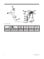
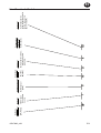
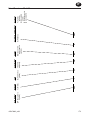
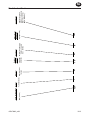
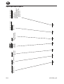
4
7
5
3
2
1
9
10
6
48h
1m
PMAX
24h
8
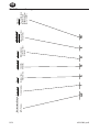
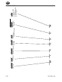
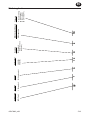
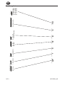
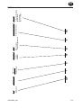
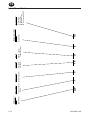
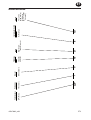
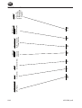
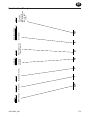
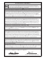
(Dwg. 16608929)
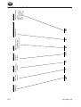
1
3
2
5
6
9
10
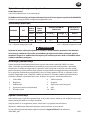
IR # - NPT IR # - BS inch (mm) NPT IR # IR #
C38121-800 C381B1-800 1/4 (6) 1/4 10 67

45587003_ed3 EN-1
EN
Product Safety Information
Intended Use:
These Air Drills are designed for tapping operations.
For additional information refer to Product Safety Information Manual Form 04580353.
Manuals can be downloaded from Ingersollrandproducts.com.
Product Specications
Model(s) Style
Free
Speed
Chuck
Capacity
Sound Level dB (A)
(ISO15744)
Vibration m/s²
(ISO28927)
rpm in (mm) † Pressure (L
p
) ‡ Power (L
w
) Level
QP1S10D8 Pistol 1000 1/4 (6) 78.1 -- <2.5
QP1S05D8 Pistol 500 1/4 (6) 78.1 -- <2.5
† K
pA
= 3dB measurement uncertainty ‡ K
wA
= 3dB measurement uncertainty
WARNING
Sound and vibration values were measured in compliance with internationally recognized
test standards. The exposure to the user in a specic tool application may vary from these
results. Therefore, on site measurements should be used to determine the hazard level in
that specic application.
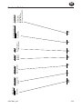
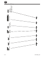
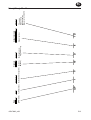
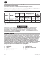
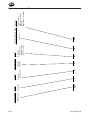
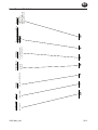
Installation and Lubrication
Size air supply line to ensure tool’s maximum operating pressure (PMAX) at tool inlet. Drain
condensate from valve(s) at low point(s) of piping, air lter and compressor tank daily. Install
a properly sized Safety Air Fuse upstream of hose and use an anti-whip device across any
hose coupling without internal shut-o, to prevent hose whipping if a hose fails or coupling
disconnects. See drawing 16608929 and table on page 2. Maintenance frequency is shown in
circular arrow and dened as h=hours, d=days, and m=months of actual use. Items identied as:
1. Air lter 6. Thread size
2. Regulator 7. Coupling
3. Lubricator 8. Safety Air Fuse
4. Emergency shut-o valve 9. Oil
5. Hose diameter 10. Grease
Parts and Maintenance
When the life of the tool has expired, it is recommended that the tool be disassembled,
degreased and parts be separated by material so that they can be recycled.
Original instructions are in English. Other languages are a translation of the original instructions.
Tool repair and maintenance should only be carried out by an authorized Service Center.
Refer all communications to the nearest Ingersoll Rand Oce or Distributor.

EN-2 45587003_ed3
EN
Model Identication
Accessory
Bit Holder or Driver
Clutch
Free Speed
Throttle
Rotation
Tool Style
TD
8
D
10
S
1
QP
QP (Pistol)
8 (Tapper)
1 (Reversible) S (Trigger Start)
10 (1000)
05 (0500)
D (Direct Drive;
Trigger Start only)
T (Top Inlet)
A (Small Grip)
D (Memory Chip)
B (1/4-19 BSPT Inlet)

45587003_ed3 ES-1
ES
Información de Seguridad Sobre el Producto
Uso Indicado:
Estos taladros neumáticos están diseñados para realizar perforaciones.
Para obtener más información, consulte el formulario 04580353 del manual de
información de seguridad del producto.
Los manuales pueden descargarse desde ingersollrandproducts.com
Especicaciones del Producto
Modelo(s) Estilo
Velocidad
Libre
Capacidad del
Portabrocas
Nivel Sonoro dB(A)
(ISO15744)
Vibración (m/s²)
(ISO28927)
rpm pulg. (mm) † Presión (L
p
) ‡ Potencia (L
w
) Nivel
QP1S10D8 Pistola 1000 1/4 (6) 78.1 --- <2.5
QP1S05D8 Pistola 500 1/4 (6) 78.1 --- <2.5
† K
pA
= 3dB de error
‡ K
wA
= 3dB de errored
ADVERTENCIA
Los valores de ruido y vibración se han medido de acuerdo con los estándares para prue-
bas reconocidos internacionalmente. Es posible que la exposición del usuario en una apli-
cación especíca de herramienta diera de estos resultados. Por lo tanto, la mediciones in
situ se deberían utilizar para determinar el nivel de riesgo en esa aplicación especíca.
Instalación y Lubricación
Ajuste la línea de suministro de aire para asegurar la máxima presión de funcionamiento (PMAX)
de la herramienta en su entrada. Vacíe el condensado de las válvulas en los puntos inferiores
de la canalización, ltro de aire y depósito del compresor diariamente. Instale una válvula de
seguridad de tamaño adecuado y utilice un dispositivo antilatigazos en cualquier acoplamiento
de manguera sin apagador interno para evitar que las mangueras den latigazos en caso de que
falle una manguera o de que se desconecte el acoplamiento. Consulte la ilustración 16608929 de
la página 2. La frecuencia de mantenimiento se muestra dentro de una echa circular y se dene
como h = horas, d = días y m = meses de uso real. Los elementos se identican como:
1. Filtro de aire 6. Tamaño de la rosca
2. Regulador 7. Acoplamiento
3. Lubricante 8. Dispositivo de seguridad
4. Válvula de corte de emergencia 9. Aceite
5. Diámetro de la manguera 10. Grasa

ES-2 45587003_ed3
ES
Piezas y Mantenimiento
Una vez agotada la vida útil de la herramienta, se recomienda desarmarla, desengrasarla y
agrupar las piezas en función del material del que están fabricadas para reciclarlas.
Las instrucciones originales están en inglés. Las demás versiones son una traducción de las
instrucciones originales.
Las labores de reparación y mantenimiento de las herramientas sólo pueden realizarse en un
centro de servicio autorizado.
Remita todas las comunicaciones a la ocina o distribuidor de Ingersoll Rand más cercano.

45587003_ed3 ES-3
ES
Identicación de Modelos
Accesorio
Portapuntas o
cuadradrillo
Embrague
Velocidad
en vacío
Palanca de mando
Rotación
Estilo de
herramienta
TD
8
D
10
S
1
QP
QP (Pistola)
8 (Roscadora)
1 (Embrague
de suministro
de aire)
S (Arranque por
gatillo)
10 (1000)
05 (0500)
D (Accionamiento directo;
arranque por gatillo
solamente)
T (entrada superior)
A (empuñadura pequeña)
D (chip de memoria)
B (1/4-19 BSPT)

FR-1 45587003_ed3
FR
Consignes de Sécurité du Produit
Utilisation Prévue:
Ces perceuses pneumatiques ont été conçues pour le taraudage.
Pour des informations complémentaires, consultez le manuel 04580353 relatif aux
informations de sécurité du produit.
Les manuels peuvent être téléchargés sur le site ingersollrandproducts.com
Spécications du produit
Modèle(s)
Burin Vit. Libre
Capacité du
Mandrin
Niveau Sonore dB (A)
(ISO15744)
Vibration
(m/s²)
(ISO28927)
tr/min pouces (mm) † Pression (L
p
) ‡ Puissance (L
w
) Niveau
QP1S10D8 Pistolet 1000 1/4 (6) 78.1 --- <2.5
QP1S05D8 Pistolet 500 1/4 (6) 78.1 --- <2.5
† K
pA
= incertitude de mesure de 3dB
‡ K
wA
= incertitude de mesure de 3dB
AVERTISSEMENT
Les valeurs sonores et vibratoires ont été mesurées dans le respect des normes de tests
reconnues au niveau international. L’exposition de l’utilisateur lors d’une application
d’outil spécique peut diérer de ces résultats. Par conséquent, il faut utiliser des mesures
sur site an de déterminer le niveau de risque de cette application spécique.
Installation et Lubrication
Réglez l’alimentation en air de façon à obtenir une pression de fonctionnement maximale
(PMAX) de l’outil au niveau de l’entrée. Drainez quotidiennement le condensat des vannes
situées aux points bas de la tuyauterie, du ltre à air et du réservoir du compresseur. Installez
un raccordement de sûreté pneumatique de taille appropriée en amont du tuyau et utilisez
un dispositif anti-débattement sur tous les raccords pour tuyaux sans coupure interne, an
d’empêcher les tuyaux de fouetter si l’un d’eux se décroche ou si le raccord se détache.
Reportez-vous au schéma 16608929 et au tableau de la page 2. La fréquence des opérations
d’entretien est indiquée dans la èche circulaire et est dénie en h=heures, d=jours, et m=mois
de fonctionnement. Eléments identiés en tant que:
1. Filtre à air 6. Taille du letage
2. Régulateur 7. Raccord
3. Lubricateur 8. Raccordement de sûreté pneumatique
4. Vanne d’arrêt d’urgence 9. Huile
5. Diamètre du tuyau 10. Graisse

45587003_ed3 FR-2
FR
Pièces Détachées et Maintenance
Lorsque l’outil est arrivé en n de vie, il est recommandé de le démonter, de dégraisser les pièces
et de trier ces dernières par matériau de manière à pouvoir les recycler.
Les instructions d’origine sont en anglais. Les autres langues sont une traduction des instructions
d’origine.
Seul un centre de service agréé peut eectuer la réparation et la maintenance des outils.
Transmettez toutes vos communications au bureau ou au distributeur Ingersoll Rand le
plus proche.

FR-3 45587003_ed3
FR
Identication des Modèles
Accessoire
Porte-embout ou entraîneur
Limiteur
Vitesse à vide
Commande
Rotation
Style d’outil
TD
8
D
10
S
1
QP
QP (Pistolet)
8 (Taraudeuse)
1 (Gâchette
-poussoir)
S (Déclenchement
gâchette)
10 (1000)
05 (0500)
D (Entraînement direct
- Démarrage par
gâchette seulement)
T (Admission par le
haut)
A (Petite poignée)
D (Puce mémoire)
B (1/4-19 BSPT
Tuyau d’entrée)

45587003_ed3 IT-1
IT
Informazioni sulla Sicurezza del Prodotto
Destinazione D’uso:
Questi trapani pneumatici sono adatti per operazioni di maschiatura.
Per ulteriori informazioni, consultare il modulo 04580353 del Manuale contenente le
informazioni sulla sicurezza del prodotto.
I manuali possono essere scaricati dal sito ingersollrandproducts.com
Speciche del Prodotto
Modello/i Stile
Velocità a
Vuoto
Capacità del
Mandrino
Livello Sonoro dB (A)
(ISO15744)
Vibrazioni
(m/s²)
(ISO28927)
giri al
minuto
poll. (mm) † Pressione (L
p
) ‡ Potenza (L
w
) Livello
QP1S10D8 Impugnatura 1000 1/4 (6) 78.1 --- <2.5
QP1S05D8 Impugnatura 500 1/4 (6) 78.1 --- <2.5
† K
pA
= incertezza misurazione 3dB
‡ K
wA
= incertezza misurazione 3dB
AVVERTIMENTO
I valori relativi a suoni e vibrazioni sono stati misurati in conformità agli standard di test
riconosciuti a livello internazionale. L’esposizione all’utente nell’applicazione di uno
specico strumento può variare rispetto ai presenti risultati. Pertanto, sarebbe necessario
utilizzare le misurazioni in loco per determinare il livello di pericolo della specica ap-
plicazione.
Installazione e Lubricazione
La linea di alimentazione dell’aria deve essere dimensionata in maniera tale da assicurare
all’utensile la massima pressione di esercizio (PMAX) in ingresso. Scaricare quotidianamente la
condensa dalla valvola o dalle valvole sulla parte bassa della tubatura, dal ltro dell’aria e dal
serbatoio del compressore. Installare un fusibile di sicurezza di dimensioni adatte a monte del
tubo essibile e utilizzare un dispositivo antivibrazioni su tutti i manicotti senza arresto interno
per evitare i colpi di frusta dei essibili, se questi si guastano o se si staccano gli accoppiamenti.
Vedere il disegno 16608929 e la tabella a pag. 2. La frequenza di manutenzione viene illustrata
da una freccia circolare e denita con h=ore, d=giorni (days) e m=mesi di uso eettivo.
Componenti:
1. Filtro dell’aria 6. Dimensione della lettatura
2. Regolatore 7. Accoppiamento
3. Ingrassatore 8. Fusibile di sicurezza
4. Valvola di arresto di emergenza 9. Olio
5. Diametro tubo essibile 10. Grasso

IT-2 45587003_ed3
IT
Ricambi e Manutenzione
Raggiunto il limite di operatività dell’utensile, si consiglia di smontarlo, sgrassarlo e separare i
pezzi in base al materiale con il quale sono costituiti, in modo da poterli riciclare.
Le istruzioni originali sono in lingua inglese. Le altre lingue sono una traduzione delle istruzioni
originali.
La riparazione e la manutenzione dell’utensile devono essere eseguite soltanto da un centro di
assistenza autorizzato.
Per qualsiasi comunicazione, rivolgersi all’ucio o al rivenditore Ingersoll Rand più vicino.

45587003_ed3 IT-3
IT
Identicazione Modello
Accessori
Portapunta o trasmissione
Frizione
Velocità libera
Leva
Rotazione
Stile attrezzo
TD
8
D
10
S
1
QP
QP (Impugnatura
a pistola )
1 (Farfalla)
8 (Filettatrici)
S (Avviamento a
grilletto)
10 (1000)
05 (0500)
D (Attacco diretto;
solo Avviamento
a grilletto)
T (Ingresso
superiore)
A (Impugnatura
piccola)
D (Chip di memoria)
B (1/4-19 BSPT)

DE-1 45587003_ed3
DE
Produktsicherheitsinformationen
Beabsichtigte Verwendung:
Diese Druckluft-Bohrmaschinen sind zum Gewindeschneiden konzipiert.
Die Kappen von Umsteuer- und Betätigungsventil stehen unter Federdruck. Lassen Sie
Vorsicht walten, wenn Sie die Kappen entfernen.
Handbücher können von ingersollrandproducts.com heruntergeladen werden.
Technische Produktdaten
Modell(e) Machart
Nenndreh-
zahl
Kapazität
Spannfutter
Schallpegel dB (A)
(ISO15744)
Schwingungs
(m/s²)
(ISO28927)
rpm Zoll (mm) † Druck (L
p
) ‡ Stromzufuhr (L
w
) Spegel
QP1S10D8 Pistole 1000 1/4 (6) 78.1 --- <2.5
QP1S05D8 Pistole 500 1/4 (6) 78.1 --- <2.5
† K
pA
= 3dB Messunsicherheit
‡ K
wA
= 3dB Messunsicherheit
WARNUNG
Schall- und Vibrationswerte wurden gemäß den international anerkannten Teststandards
gemessen. Die tatsächlichen Werte, denen der Benutzer während der Anwendung eines
bestimmten Werkzeugs ausgesetzt ist, können von diesen Ergebnissen abweichen. Vor
Ort sollten daher Maßnahmen getroen werden, um die Gefahrenstufe der jeweiligen
Anwendung zu bestimmen.
Montage und Schmierung
Druckluftzufuhrleitung an der Druckluftzufuhr des Werkzeugs gemäß des maximalen
Betriebsdrucks (PMAX) bemessen. Kondensat an den Ventilen an Tiefpunkten von Leitungen,
Luftlter und Kompressortank täglich ablassen. Eine Sicherheits- Druckluftsicherung gegen die
Strömungsrichtung im Schlauch und eine Anti- Schlagvorrichtung an jeder Verbindung ohne
interne Sperre installieren, um ein Peitschen des Schlauchs zu verhindern, wenn ein Schlauch
fehlerhaft ist oder sich eine Verbindung löst. Siehe Zeichnung 16608929 und Tabelle auf
Seite 2. Die Wartungshäugkeit mit einem Pfeil eingekreist und ist deniert in h=Stunden,
d=Tagen und m=Monaten der tatsächlichen Verwendung. Teile:
1. Luftlter 6. Gewindegröße
2. Regler 7. Verbindung
3. Schmierbüchse 8. Sicherheits-Druckluftsicherung
4. Notabsperrventil 9. Ölen
5. Schlauchdurchmesser 10. Fetten

45587003_ed3 DE-2
DE
Teile und Wartung
Zur Entsorgung ist das Werkzeug vollständig zu demontieren, zu entfetten und nach
Materialarten getrennt der Wiederverwertung zuzuführen.
Die Originalanleitung ist in englischer Sprache verfasst. Bei anderen Sprachen handelt es sich um
ein Übersetzung der Originalanleitung.
Die Werkzeug-Reparatur und -Wartung darf nur von einem autorisierten Wartungszentrum
durchgeführt werden.
Wenden Sie sich bei Rückfragen an Ihre nächste Ingersoll Rand Niederlassung oder den
autorisierten Fachhandel.

DE-3 45587003_ed3
DE
Modellkennzeichnung
Zubehör
Schraubvorsatz
oder Antrieb
Kupplung
Freie Drehzahl
Drossel
Drehrichtung
Werkzeugausführung
TD
8
D
10
S
1
QP
QP (Pistole) 1 (Umschaltbar)
8 (Gewindeschnei-
dmaschinen)
S (Anlauf über
Kombinierter)
10 (1000)
05 (0500)
D (Direktantrieb;
nur Anlauf über
Drücker)
T (Lufteinlaß oben)
A (Kleiner Griff)
D (Speicher-Chip)
B (1/4-19 BSPT)

45587003_ed3 NL-1
NL
Productveiligheidsinformatie
Bedoeld Gebruik:
Deze pneumatische boormachines zijn bedoeld voor tapwerkzaamheden.
Zie formulier 04580353 van de productveiligheidshandleiding voor aanvullende
informatie.
Handleidingen kunnen worden gedownload vanaf ingersollrandproducts.com
Productspecicaties
Model(len) Soort
Onbelast
Toerental
Capaciteit
Houder
Geluidsniveau dB(A)
(ISO15744)
Trillings (m/s²)
(ISO28927)
tpm in. (mm) † Druk (L
p
) ‡ Vermogen (L
w
) Niveau
QP1S10D8 Pistool 1000 1/4 (6) 78.1 --- <2.5
QP1S05D8 Pistool 500 1/4 (6) 78.1 --- <2.5
† Meetonnauwkeurigheid bij K
pA
= 3dB
‡ Meetonnauwkeurigheid bij K
wA
= 3dB
WAARSCHUWING
Geluids- en vibratiewaarden worden gemeten in overeenstemming met internationaal
erkende testnormen. De blootstelling van een gebruiker bij een specieke toepassing van
gereedschap kan afwijken van deze resultaten. Daarom moeten er op locatie metingen
worden genomen om het gevaarniveau in die specieke toepassing te bepalen.
Installatie en Smering
Meet luchttoevoerleiding om zeker te zijn van maximale bedrijfsdruk (PMAX) van gereedschap
bij gereedschapsinlaat. Tap dagelijks condensaat af van kleppen bij lage punten van leidingwerk,
luchtlter en compressortank. Monteer een debiet-afslagklep met de juiste afmeting
bovenstrooms van de slang en gebruik een antislingerelement op elke slangkoppeling zonder
interne afsluiter om te voorkomen dat de slang gaat slingeren als een koppeling losraakt of
bij slangbreuk. Zie tekening 16608929 en tabel op pagina 2. De onderhoudsfrequentie wordt
weergegeven in een cirkelvormige pijl met h=uren, d=dagen en m=maanden reëel gebruik.
Aangegeven onderdelen:
1. Luchtlter 6. Tapmaat
2. Regelaar 7. Koppeling
3. Smeerinrichting 8. Debiet-afslagklep
4. Noodafsluitklep 9. Olie
5. Slangdiameter 10. Smeren

NL-2 45587003_ed3
NL
Onderdelen en Onderhoud
Als het gereedschap niet meer wordt gebruikt vanwege ouderdom, slijtage of defecten, wordt
u geadviseerd het gereedschap te demonteren en de onderdelen te ontvetten en te scheiden
voor recycling.
De originele instructies zijn opgesteld in het Engels. Andere talen zijn een vertaling van de
originele instructies.
Reparatie en onderhoud van dit gereedschap mogen uitsluitend door een erkend
servicecentrum worden uitgevoerd.
Voor alle communicatie wordt u verwezen naar de dichtstbijzijnde Ingersoll Rand vestiging
of dealer.

45587003_ed3 NL-3
NL
Modelindenticatie
Toebehoren
Bithouder of
aandrijving
Koppeling
Onbelast
toerental
Regelaar
Rotatie
Type gereedschap
TD
8
D
10
S
1
QP
QP (Pistool)
1 (Omkeerbaar)
8 (Tapmachine)
S (Starten m.b.v.
trekker)
10 (1000)
05 (0500)
D (Directe aandrijving;
Starten uitsluitend
m.b.v. trekker)
T (Bovenste inlaat)
A (Kleine handgreep)
D (Geheugenchip)
B (1/4-19 BSPT)

DA-1 45587003_ed3
DA
Produktsikkerhedsinformation
Anvendelsesområder:
Disse trykluftbor er udformet til gevindskæring.
For yderligere oplysninger henvises der til formular 04580353 i vejledningen med
produktsikkerhedsinformation.
Vejledninger kan downloades fra ingersollrandproducts.com
Produktspecikationer
Model(ler) Stil
Fri
Hastighed
Borepatron-
skapacitet
Lydniveau dB(A)
(ISO15744)
Vibrations (m/s²)
(ISO28927)
rpm tommer (mm) † Tryk (L
p
) ‡ Eekt (L
w
) Niveau
QP1S10D8 Pistol 1000 1/4 (6) 78.1 --- <2.5
QP1S05D8 Pistol 500 1/4 (6) 78.1 --- <2.5
† K
pA
= 3dB måleusikkerhed
‡ K
wA
= 3dB måleusikkerhed
ADVARSEL
Lyd- og vibrationsværdier blev målt i overensstemmelse med internationalt anerkendte
teststandarder. Brugerens eksponering under en specik værktøjsanvendelse kan adskille
sig fra disse resultater. Derfor bør der anvendes stedspecikke målinger til at bedømme
fareniveauet for denne specikke anvendelse.
Installation og Smøring
Sørg for at lufttilførselsledningen har den korrekte størrelse for at sikre maksimalt driftstryk
(PMAX) ved værktøjsindgangen. Tøm dagligt ventilen(-erne) for kondensat ved rørenes,
luftlterets og kompressortankens lavpunkt(er). Montér en sikkerhedstryksikring i korrekt
størrelse op ad slangen og brug en anti-piskeanordning tværs over eventuelle slangekoblinger
uden intern aukning for at forhindre, at slangen pisker, hvis en slange svigter, eller koblingen
frakobles. Se tegning 16608929 og tabellen på side 2. Vedligeholdelseshyppigheden vises med
en rund pil og deneres som t=timer, d=dage og m=måneder for reel brug. Elementerne er
identiceret som:
1. Luftlter 6. Gevindstørrelse
2. Regulator 7. Kobling
3. Smøreapparat 8. Sikkerhedstryksikring
4. Nødafspærringsventil 9. Olie
5. Slangediameter 10. Smøre
Pagina se încarcă...
Pagina se încarcă...
Pagina se încarcă...
Pagina se încarcă...
Pagina se încarcă...
Pagina se încarcă...
Pagina se încarcă...
Pagina se încarcă...
Pagina se încarcă...
Pagina se încarcă...
Pagina se încarcă...
Pagina se încarcă...
Pagina se încarcă...
Pagina se încarcă...
Pagina se încarcă...
Pagina se încarcă...
Pagina se încarcă...
Pagina se încarcă...
Pagina se încarcă...
Pagina se încarcă...
Pagina se încarcă...
Pagina se încarcă...
Pagina se încarcă...
Pagina se încarcă...
Pagina se încarcă...
Pagina se încarcă...
Pagina se încarcă...
Pagina se încarcă...
Pagina se încarcă...
Pagina se încarcă...
Pagina se încarcă...
Pagina se încarcă...
Pagina se încarcă...
Pagina se încarcă...
Pagina se încarcă...
Pagina se încarcă...
Pagina se încarcă...
Pagina se încarcă...
Pagina se încarcă...
Pagina se încarcă...
Pagina se încarcă...
Pagina se încarcă...
Pagina se încarcă...
Pagina se încarcă...
Pagina se încarcă...
Pagina se încarcă...
Pagina se încarcă...
Pagina se încarcă...
Pagina se încarcă...
Pagina se încarcă...
Pagina se încarcă...
Pagina se încarcă...
Pagina se încarcă...
Pagina se încarcă...
Pagina se încarcă...
Pagina se încarcă...
-
 1
1
-
 2
2
-
 3
3
-
 4
4
-
 5
5
-
 6
6
-
 7
7
-
 8
8
-
 9
9
-
 10
10
-
 11
11
-
 12
12
-
 13
13
-
 14
14
-
 15
15
-
 16
16
-
 17
17
-
 18
18
-
 19
19
-
 20
20
-
 21
21
-
 22
22
-
 23
23
-
 24
24
-
 25
25
-
 26
26
-
 27
27
-
 28
28
-
 29
29
-
 30
30
-
 31
31
-
 32
32
-
 33
33
-
 34
34
-
 35
35
-
 36
36
-
 37
37
-
 38
38
-
 39
39
-
 40
40
-
 41
41
-
 42
42
-
 43
43
-
 44
44
-
 45
45
-
 46
46
-
 47
47
-
 48
48
-
 49
49
-
 50
50
-
 51
51
-
 52
52
-
 53
53
-
 54
54
-
 55
55
-
 56
56
-
 57
57
-
 58
58
-
 59
59
-
 60
60
-
 61
61
-
 62
62
-
 63
63
-
 64
64
-
 65
65
-
 66
66
-
 67
67
-
 68
68
-
 69
69
-
 70
70
-
 71
71
-
 72
72
-
 73
73
-
 74
74
-
 75
75
-
 76
76


Ingersoll-Rand QP1S Series Informații despre produs
- Tip
- Informații despre produs
în alte limbi
Lucrări înrudite
-
Ingersoll-Rand 728LA2 Informații despre produs
-
-
-
Ingersoll-Rand 7807R-EU Informații despre produs
-
Ingersoll-Rand QS091BD Informații despre produs
-
Ingersoll-Rand QP151D Informații despre produs
-
-
-
Ingersoll-Rand LD22 Serie Informații despre produs
-