
Robert Bosch Power Tools GmbH
70538 Stuttgart
GERMANY
www.bosch-pt.com
1 609 92A 3PW (2017.04) T / 219
GLL 3-80 Professional
de Originalbetriebsanleitung
en Original instructions
fr Notice originale
es Manual original
pt Manual original
it Istruzioni originali
nl Oorspronkelijke gebruiksaanwijzing
da Original brugsanvisning
sv Bruksanvisning i original
no Original driftsinstruks
fi Alkuperäiset ohjeet
el Πρωτότυπο οδηγιών χρήσης
tr Orijinal işletme talimatı
pl Instrukcja oryginalna
cs Původní návod k používání
sk Pôvodný návod na použitie
hu Eredeti használati utasítás
ru Оригинальное руководство по
эксплуатации
uk Оригінальна інструкція з
експлуатації
kk Пайдалану нұсқаулығының
түпнұсқасы
ro Instrucţiuni originale
bg Оригинална инструкция
mk Оригинално упатство за работа
sr Originalno uputstvo za rad
sl Izvirna navodila
hr Originalne upute za rad
et Algupärane kasutusjuhend
lv Instrukcijas oriģinālvalodā
lt Originali instrukcija
ja オリジナル取扱説明書
cn 正本使用说明书
tw 原始使用說明書
ko 사용 설명서 원본
th หนังสือคู่มือการใช้งานฉบับต้นแบบ
id Petunjuk-Petunjuk untuk
Penggunaan Orisinal
vi
Bản gốc hướng dẫn sử dụng
ar
fa
ςТЎϩХʉ ЌТϾϦφЍʉ ʌμВТЎϺυ
ΖЎϩʉ ˒μВЖЙʉʓ ИͳϞφЁʑ
OBJ_BUCH-3085-001.book Page 1 Thursday, April 27, 2017 11:21 AM

2 |
1 609 92A 3PW | (27.4.17) Bosch Power Tools
Deutsch. . . . . . . . . . . . . . . . . . . . . . . . . . . . . . . . . . . . . . . . . Seite 6
English . . . . . . . . . . . . . . . . . . . . . . . . . . . . . . . . . . . . . . . . . . Page 11
Français . . . . . . . . . . . . . . . . . . . . . . . . . . . . . . . . . . . . . . . . . Page 17
Español. . . . . . . . . . . . . . . . . . . . . . . . . . . . . . . . . . . . . . . . Página 23
Português . . . . . . . . . . . . . . . . . . . . . . . . . . . . . . . . . . . . . . Página 29
Italiano . . . . . . . . . . . . . . . . . . . . . . . . . . . . . . . . . . . . . . . . Pagina 35
Nederlands. . . . . . . . . . . . . . . . . . . . . . . . . . . . . . . . . . . . . Pagina 40
Dansk . . . . . . . . . . . . . . . . . . . . . . . . . . . . . . . . . . . . . . . . . . . Side 46
Svenska . . . . . . . . . . . . . . . . . . . . . . . . . . . . . . . . . . . . . . . . . Sida 51
Norsk. . . . . . . . . . . . . . . . . . . . . . . . . . . . . . . . . . . . . . . . . . . . Side 56
Suomi . . . . . . . . . . . . . . . . . . . . . . . . . . . . . . . . . . . . . . . . . . . Sivu 61
Ελληνικά . . . . . . . . . . . . . . . . . . . . . . . . . . . . . . . . . . . . . . . Σελίδα 66
Türkçe. . . . . . . . . . . . . . . . . . . . . . . . . . . . . . . . . . . . . . . . . . Sayfa 72
Polski . . . . . . . . . . . . . . . . . . . . . . . . . . . . . . . . . . . . . . . . . Strona 77
Česky . . . . . . . . . . . . . . . . . . . . . . . . . . . . . . . . . . . . . . . . . Strana 83
Slovensky . . . . . . . . . . . . . . . . . . . . . . . . . . . . . . . . . . . . . . Strana 88
Magyar . . . . . . . . . . . . . . . . . . . . . . . . . . . . . . . . . . . . . . . . . Oldal 93
Русский . . . . . . . . . . . . . . . . . . . . . . . . . . . . . . . . . . . . Страница 99
Українська . . . . . . . . . . . . . . . . . . . . . . . . . . . . . . . . . . . Сторінка 106
Қазақша . . . . . . . . . . . . . . . . . . . . . . . . . . . . . . . . . . . . . . . . . . Бет 112
Română. . . . . . . . . . . . . . . . . . . . . . . . . . . . . . . . . . . . . . . . Pagina 118
Български . . . . . . . . . . . . . . . . . . . . . . . . . . . . . . . . . . Страница 124
Македонски . . . . . . . . . . . . . . . . . . . . . . . . . . . . . . . . . . . Страна 130
Srpski . . . . . . . . . . . . . . . . . . . . . . . . . . . . . . . . . . . . . . . . . Strana 135
Slovensko . . . . . . . . . . . . . . . . . . . . . . . . . . . . . . . . . . . . . . . Stran 140
Hrvatski. . . . . . . . . . . . . . . . . . . . . . . . . . . . . . . . . . . . . . . Stranica 145
Eesti . . . . . . . . . . . . . . . . . . . . . . . . . . . . . . . . . . . . . . . . Lehekülg 150
Latviešu . . . . . . . . . . . . . . . . . . . . . . . . . . . . . . . . . . . . . . Lappuse 156
Lietuviškai. . . . . . . . . . . . . . . . . . . . . . . . . . . . . . . . . . . . . Puslapis 161
日本語 . . . . . . . . . . . . . . . . . . . . . . . . . . . . . . . . . . . . . . . . . . . ページ 166
中文 . . . . . . . . . . . . . . . . . . . . . . . . . . . . . . . . . . . . . . . . . . . . . . . . . 页172
中文 . . . . . . . . . . . . . . . . . . . . . . . . . . . . . . . . . . . . . . . . . . . . . . . . . 頁177
한국어 . . . . . . . . . . . . . . . . . . . . . . . . . . . . . . . . . . . . . . . . . . . . . . 페이지 182
. . . . . . . . . . . . . . . . . . . . . . . . . . . . . . . . . . . . . . . . 187
Bahasa Indonesia. . . . . . . . . . . . . . . . . . . . . . . . . . . . . . Halaman 193
Tiếng Việt
. . . . . . . . . . . . . . . . . . . . . . . . . . . . . . . . . . . . . . .
Trang
199
. . . . . . . . . . . . . . . . . . . . . . . . . . . . . . . . . . . . . . . . . 212
. . . . . . . . . . . . . . . . . . . . . . . . . . . . . . . . . . . . . . . 218
OBJ_BUCH-3085-001.book Page 2 Thursday, April 27, 2017 11:41 AM

3 |
1 609 92A 3PW | (27.4.17) Bosch Power Tools
17
1 608 M00 05B
21
23
BT 150
0 601 096 B00
LR 7
0 601 069 J00
LR 6
0 601 069 H00
20
15
BM 1
0 601 015 A01
22
GCC 30-4
1 600 A01 1..
24
BT 350
0 601 015 B00
16
1 608 M00 C20
19
1 608 M00 C1Y
18
OBJ_BUCH-3085-001.book Page 3 Thursday, April 27, 2017 11:41 AM

1 609 92A 3PW | (27.4.17) Bosch Power Tools
4 |
1
23
456
98
7
10
13
14
12
11
1
1
GLL 3-80
OBJ_BUCH-3085-001.book Page 4 Thursday, April 27, 2017 11:41 AM

5 |
1 609 92A 3PW | (27.4.17) Bosch Power Tools
FE
DC
BA
OBJ_BUCH-3085-001.book Page 5 Thursday, April 27, 2017 11:41 AM

6 | Deutsch
1 609 92A 3PW | (27.4.17) Bosch Power Tools
Deutsch
Sicherheitshinweise
Sämtliche Anweisungen sind zu lesen und
zu beachten, um mit dem Messwerkzeug ge-
fahrlos und sicher zu arbeiten. Wenn das
Messwerkzeug nicht entsprechend den vor-
liegenden Anweisungen verwendet wird,
können die integrierten Schutzvorkehrungen im Mess-
werkzeug beeinträchtigt werden. Machen Sie Warnschil-
der am Messwerkzeug niemals unkenntlich. BEWAHREN
SIE DIESE ANWEISUNGEN GUT AUF UND GEBEN SIE SIE
BEI WEITERGABE DES MESSWERKZEUGS MIT.
Vorsicht – wenn andere als die hier angegebenen Be-
dienungs- oder Justiereinrichtungen benutzt oder an-
dere Verfahrensweisen ausgeführt werden, kann dies
zu gefährlicher Strahlungsexposition führen.
Das Messwerkzeug wird mit einem Warnschild ausge-
liefert (in der Darstellung des Messwerkzeugs auf der
Grafikseite mit Nummer 12 gekennzeichnet).
Ist der Text des Warnschildes nicht in Ihrer Landes-
sprache, dann überkleben Sie ihn vor der ersten Inbe-
triebnahme mit dem mitgelieferten Aufkleber in Ihrer
Landessprache.
Richten Sie den Laserstrahl nicht auf
Personen oder Tiere und blicken Sie
nicht selbst in den direkten oder reflek-
tierten Laserstrahl. Dadurch können Sie
Personen blenden, Unfälle verursachen
oder das Auge schädigen.
Falls Laserstrahlung ins Auge trifft, sind die Augen be-
wusst zu schließen und der Kopf sofort aus dem Strahl
zu bewegen.
Nehmen Sie keine Änderungen an der Lasereinrich-
tung vor.
Verwenden Sie die Laser-Sichtbrille nicht als Schutz-
brille. Die Laser-Sichtbrille dient zum besseren Erkennen
des Laserstrahls, sie schützt jedoch nicht vor der Laser-
strahlung.
Verwenden Sie die Laser-Sichtbrille nicht als Sonnen-
brille oder im Straßenverkehr. Die Laser-Sichtbrille
bietet keinen vollständigen UV-Schutz und vermindert die
Farbwahrnehmung.
Lassen Sie das Messwerkzeug von qualifiziertem Fach-
personal und nur mit Original-Ersatzteilen reparieren.
Damit wird sichergestellt, dass die Sicherheit des Mess-
werkzeuges erhalten bleibt.
Lassen Sie Kinder das Laser-Messwerkzeug nicht un-
beaufsichtigt benutzen. Sie könnten unbeabsichtigt Per-
sonen blenden.
Arbeiten Sie mit dem Messwerkzeug nicht in explo-
sionsgefährdeter Umgebung, in der sich brennbare
Flüssigkeiten, Gase oder Stäube befinden. Im Mess-
werkzeug können Funken erzeugt werden, die den Staub
oder die Dämpfe entzünden.
Beim Betrieb des Messwerkzeugs ertönen unter be-
stimmten Bedingungen laute Signaltöne. Halten Sie
deshalb das Messwerkzeug vom Ohr bzw. von anderen
Personen fern. Der laute Ton kann das Gehör schädigen.
Bringen Sie das Messwerkzeug, die Laser-
Zieltafel 18 und die universelle Halterung
15 nicht in die Nähe von Herzschrittma-
chern. Durch die Magnete des Messwerk-
zeugs, der Laser-Zieltafel und der universellen
Halterung wird ein Feld erzeugt, das die Funk-
tion von Herzschrittmachern beeinträchtigen
kann.
Halten Sie das Messwerkzeug, die Laser-Zieltafel 18
und die universelle Halterung 15 fern von magneti-
schen Datenträgern und magnetisch empfindlichen
Geräten. Durch die Wirkung der Magnete des Messwerk-
zeugs, der Laser-Zieltafel und der universellen Halterung
kann es zu irreversiblen Datenverlusten kommen.
Produkt- und Leistungsbeschreibung
Bitte klappen Sie die Ausklappseite mit der Darstellung des
Messwerkzeugs auf, und lassen Sie diese Seite aufgeklappt,
während Sie die Betriebsanleitung lesen.
Bestimmungsgemäßer Gebrauch
Das Messwerkzeug ist bestimmt zum Ermitteln und Über-
prüfen von waagrechten und senkrechten Linien.
Abgebildete Komponenten
Die Nummerierung der abgebildeten Komponenten bezieht
sich auf die Darstellung des Messwerkzeugs auf der Grafik-
seite.
1Austrittsöffnung Laserstrahlung
2Batterie-Anzeige
3Anzeige Arbeiten ohne Nivellierautomatik
4Taste Empfängermodus
5Anzeige Empfängermodus
6Taste für Laser-Betriebsart
7Ein-/Ausschalter
8Stativaufnahme 1/4"
9Stativaufnahme 5/8"
10 Arretierung des Batteriefachdeckels
11 Batteriefachdeckel
12 Laser-Warnschild
13 Seriennummer
14 Aussparung für nachrüstbares Bluetooth®-Modul
15 Universelle Halterung*
16 Laserempfänger*
17 Laser-Sichtbrille*
18 Laser-Zieltafel*
OBJ_BUCH-3085-001.book Page 6 Thursday, April 27, 2017 11:41 AM

Deutsch | 7
Bosch Power Tools 1 609 92A 3PW | (27.4.17)
19 Koffer*
20 Einlage*
21 Schutztasche*
22 Nachrüstbares Bluetooth®-Modul*
23 Stativ*
24 Teleskopstange*
* Abgebildetes oder beschriebenes Zubehör gehört nicht zum
Standard-Lieferumfang.
Technische Daten
Montage
Batterien einsetzen/wechseln
Für den Betrieb des Messwerkzeugs wird die Verwendung
von Alkali-Mangan-Batterien empfohlen.
Zum Öffnen des Batteriefachdeckels 11 ziehen Sie an der Ar-
retierung 10 und nehmen den Batteriefachdeckel ab. Setzen
Sie die Batterien ein. Achten Sie dabei auf die richtige Polung
entsprechend der Darstellung auf der Innenseite des Batte-
riefachs.
Die Batterie-Anzeige 2 zeigt immer den aktuellen Batterie-
status an:
Werden die Batterien schwach, wird die Helligkeit der Laser-
linien langsam verringert.
Ersetzen Sie immer alle Batterien gleichzeitig. Verwenden Sie
nur Batterien eines Herstellers und mit gleicher Kapazität.
Nehmen Sie die Batterien aus dem Messwerkzeug,
wenn Sie es längere Zeit nicht benutzen. Die Batterien
können bei längerer Lagerung korrodieren und sich selbst
entladen.
Betrieb
Inbetriebnahme
Schützen Sie das Messwerkzeug vor Nässe und direk-
ter Sonneneinstrahlung.
Setzen Sie das Messwerkzeug keinen extremen Tem-
peraturen oder Temperaturschwankungen aus. Lassen
Sie es z. B. nicht längere Zeit im Auto liegen. Lassen Sie das
Messwerkzeug bei größeren Temperaturschwankungen
erst austemperieren, bevor Sie es in Betrieb nehmen. Bei
extremen Temperaturen oder Temperaturschwankungen
kann die Präzision des Messwerkzeugs beeinträchtigt
werden.
Vermeiden Sie heftige Stöße oder Stürze des Mess-
werkzeuges. Nach starken äußeren Einwirkungen auf das
Messwerkzeug sollten Sie vor dem Weiterarbeiten immer
eine Genauigkeitsüberprüfung durchführen (siehe „Nivel-
liergenauigkeit“).
Schalten Sie das Messwerkzeug aus, wenn Sie es trans-
portieren. Beim Ausschalten wird die Pendeleinheit ver-
riegelt, die sonst bei starken Bewegungen beschädigt wer-
den kann.
Ein-/Ausschalten
Zum Einschalten des Messwerkzeugs schieben Sie den
Ein-/Ausschalter 7 in die Position „On“ (für Arbeiten ohne
Nivellierautomatik) oder in die Position „On“ (für Ar-
beiten mit Nivellierautomatik). Das Messwerkzeug sendet
sofort nach dem Einschalten Laserlinien aus den Austritts-
öffnungen 1.
Richten Sie den Laserstrahl nicht auf Personen oder
Tiere und blicken Sie nicht selbst in den Laserstrahl,
auch nicht aus größerer Entfernung.
Zum Ausschalten des Messwerkzeugs schieben Sie den
Ein-/Ausschalter 7 in Position „Off“. Beim Ausschalten wird
die Pendeleinheit verriegelt.
Lassen Sie das eingeschaltete Messwerkzeug nicht un-
beaufsichtigt und schalten Sie das Messwerkzeug nach
Gebrauch ab. Andere Personen könnten vom Laserstrahl
geblendet werden.
Linienlaser GLL 3-80
Sachnummer 3 601 K63 S..
Arbeitsbereich1)
–Standard
–im Empfängermodus
–mit Laserempfänger
30 m
25 m
5–120m
Nivelliergenauigkeit typisch ±0,2mm/m
Selbstnivellierbereich typisch ±4°
Nivellierzeit typisch <4s
Betriebstemperatur –10 °C ... +40 °C
Lagertemperatur –20 °C ... +70 °C
Relative Luftfeuchte max. 90 %
Laserklasse 2
Lasertyp <10 mW, 630–650 nm
C610
Divergenz Laserlinie 50 x 10 mrad (Vollwinkel)
kürzeste Impulsdauer 1/10000 s
Stativaufnahme 1/4", 5/8"
Batterien 4x1,5VLR6(AA)
Betriebsdauer mit
3 Laserebenen 4h
Gewicht entsprechend
EPTA-Procedure 01:2014 0,82 kg
Maße (Länge x Breite x Höhe) 149 x 84 x 142 mm
Schutzart IP 54 (staub- und spritz-
wassergeschützt)
1) Der Arbeitsbereich kann durch ungünstige Umgebungsbedingungen
(z.B. direkte Sonneneinstrahlung) verringert werden.
Zur eindeutigen Identifizierung Ihres Messwerkzeugs dient die Serien-
nummer 13 auf dem Typenschild.
Anzeige Kapazität
Dauerlicht grün 100–75 %
Dauerlicht gelb 75–35 %
Dauerlicht rot 35–10 %
Kein Licht Batterien leer
OBJ_BUCH-3085-001.book Page 7 Thursday, April 27, 2017 11:41 AM

8 | Deutsch
1 609 92A 3PW | (27.4.17) Bosch Power Tools
Bei Überschreiten der höchstzulässigen Betriebstemperatur
von 40 °C erfolgt die Abschaltung zum Schutz der Laser-
diode. Nach dem Abkühlen ist das Messwerkzeug wieder
betriebsbereit und kann erneut eingeschaltet werden.
Nähert sich die Temperatur des Messwerkzeugs der höchst-
zulässigen Betriebstemperatur, wird die Helligkeit der Laser-
linien langsam verringert.
Abschaltautomatik deaktivieren
Wird ca. 120 min lang keine Taste am Messwerkzeug ge-
drückt, schaltet sich das Messwerkzeug zur Schonung der
Batterien automatisch ab.
Um das Messwerkzeug nach der automatischen Abschaltung
wieder einzuschalten, können Sie entweder den Ein-/Aus-
schalter 7 erst in Position „Off“ schieben und das Messwerk-
zeug dann wieder einschalten, oder Sie drücken einmal die
Taste Laser-Betriebsart 6 oder die Taste Empfängermodus 4.
Um die Abschaltautomatik zu deaktivieren, halten Sie (bei
eingeschaltetem Messwerkzeug) die Taste Laser-Betriebsart
6 mindestens 3 s lang gedrückt. Ist die Abschaltautomatik de-
aktiviert, blinken die Laserstrahlen kurz zur Bestätigung.
Um die automatische Abschaltung zu aktivieren, schalten Sie
das Messwerkzeug aus und wieder ein.
Signalton deaktivieren
Nach dem Einschalten des Messwerkzeugs ist der Signalton
immer aktiviert.
Zum Deaktivieren bzw. Aktivieren des Signaltons drücken Sie
gleichzeitig die Taste Laser-Betriebsart 6 und die Taste Emp-
fängermodus 4 und halten sie mindestens 3 s gedrückt.
Sowohl beim Aktivieren als auch beim Deaktivieren ertönen
drei kurze Signaltöne zur Bestätigung.
Betriebsarten
Das Messwerkzeug verfügt über mehrere Betriebsarten,
zwischen denen Sie jederzeit wechseln können:
– Erzeugen einer waagrechten Laserebene,
– Erzeugen einer senkrechten Laserebene,
– Erzeugen von zwei senkrechten Laserebenen,
– Erzeugen einer waagrechten Laserebene sowie von zwei
senkrechten Laserebenen.
Nach dem Einschalten erzeugt das Messwerkzeug eine waag-
rechte Laserebene. Um die Betriebsart zu wechseln, drücken
Sie die Taste Laser-Betriebsart 6.
Alle Betriebsarten können sowohl mit als auch ohne Nivellier-
automatik gewählt werden.
Empfängermodus
Für das Arbeiten mit dem Laserempfänger 16 muss – un-
abhängig von der gewählten Betriebsart – der Empfänger-
modus aktiviert werden.
Im Empfängermodus blinken die Laserlinien mit sehr hoher
Frequenz und werden dadurch für den Laserempfänger 16
auffindbar.
Zum Einschalten des Empfängermodus drücken Sie die Taste
4. Die Anzeige 5 leuchtet grün.
Für das menschliche Auge ist die Sichtbarkeit der Laserlinien
bei eingeschaltetem Empfängermodus verringert. Für Ar-
beiten ohne Laserempfänger schalten Sie deshalb den Emp-
fängermodus durch erneutes Drücken der Taste 4 aus. Die
Anzeige 5 erlischt.
Nivellierautomatik
Arbeiten mit Nivellierautomatik
Stellen Sie das Messwerkzeug auf eine waagerechte, feste
Unterlage, befestigen Sie es auf der Halterung 15 oder dem
Stativ 23.
Schieben Sie für Arbeiten mit Nivellierautomatik den Ein-/Aus-
schalter 7 in Position „ On“.
Die Nivellierautomatik gleicht Unebenheiten innerhalb des
Selbstnivellierbereiches von ±4° automatisch aus. Die Nivel-
lierung ist abgeschlossen, sobald sich die Laserlinien nicht
mehr bewegen.
Ist die automatische Nivellierung nicht möglich, z.B. weil die
Standfläche des Messwerkzeugs mehr als 4° von der Waage-
rechten abweicht, beginnen die Laserlinien in schnellem Takt
zu blinken. Bei aktiviertem Signalton ertönt ein Signalton in
schnellem Takt.
Stellen Sie das Messwerkzeug waagerecht auf und warten Sie
die Selbstnivellierung ab. Sobald sich das Messwerkzeug in-
nerhalb des Selbstnivellierbereiches von ±4° befindet, leuch-
ten die Laserstrahlen dauerhaft und der Signalton wird abge-
schaltet.
Bei Erschütterungen oder Lageänderungen während des Be-
triebs wird das Messwerkzeug automatisch wieder einnivel-
liert. Überprüfen Sie nach einer erneuten Nivellierung die
Position der waagrechten bzw. senkrechten Laserlinie in
Bezug auf Referenzpunkte, um Fehler zu vermeiden.
Arbeiten ohne Nivellierautomatik
Schieben Sie für Arbeiten ohne Nivellierautomatik den
Ein-/Ausschalter 7 in Position „On“. Bei ausgeschalteter
Nivellierautomatik leuchtet die Anzeige 3 rot und die Laser-
linien blinken dauerhaft in langsamem Takt.
Bei abgeschalteter Nivellierautomatik können Sie das Mess-
werkzeug frei in der Hand halten oder auf eine geneigte Unter-
lage stellen. Die Laserlinien verlaufen nicht mehr zwingend
senkrecht zueinander.
Nivelliergenauigkeit
Genauigkeitseinflüsse
Den größten Einfluss übt die Umgebungstemperatur aus.
Besonders vom Boden nach oben verlaufende Temperatur-
unterschiede können den Laserstrahl ablenken.
Da die Temperaturschichtung in Bodennähe am größten ist,
sollten Sie das Messwerkzeug ab einer Messstrecke von 20 m
immer auf einem Stativ montieren. Stellen Sie das Messwerk-
zeug außerdem nach Möglichkeit in der Mitte der Arbeits-
fläche auf.
Neben äußeren Einflüssen können auch gerätespezifische
Einflüsse (wie z.B. Stürze oder heftige Stöße) zu Abweichun-
gen führen. Überprüfen Sie deshalb vor jedem Arbeitsbeginn
die Nivelliergenauigkeit.
OBJ_BUCH-3085-001.book Page 8 Thursday, April 27, 2017 11:41 AM

Deutsch | 9
Bosch Power Tools 1 609 92A 3PW | (27.4.17)
Überprüfen Sie jeweils zuerst die Nivelliergenauigkeit der
waagrechten Laserlinie und danach die Nivelliergenauigkeit
der senkrechten Laserlinien.
Sollte das Messwerkzeug bei einer der Prüfungen die maxima-
le Abweichung überschreiten, dann lassen Sie es von einem
Bosch-Kundendienst reparieren.
Waagerechte Nivelliergenauigkeit der Querachse
überprüfen
Für die Überprüfung benötigen Sie eine freie Messstrecke von
5 m auf festem Grund zwischen zwei Wänden A und B.
– Montieren Sie das Messwerkzeug nahe der Wand A auf
einem Stativ oder stellen Sie es auf festen, ebenen Unter-
grund. Schalten Sie das Messwerkzeug im Betrieb mit
Nivellierautomatik ein. Wählen Sie die Betriebsart, in der
eine waagrechte Laserebene sowie eine senkrechte Laser-
ebene frontal vor dem Messwerkzeug erzeugt werden.
– Richten Sie den Laser auf die nahe Wand A und lassen Sie
das Messwerkzeug einnivellieren. Markieren Sie die Mitte
des Punktes, an dem sich die Laserlinien an der Wand A
kreuzen (Punkt I).
– Drehen Sie das Messwerkzeug um 180°, lassen Sie es ein-
nivellieren und markieren Sie den Kreuzungspunkt der
Laserlinien an der gegenüberliegenden Wand B (Punkt II).
– Platzieren Sie das Messwerkzeug – ohne es zu drehen –
nahe der Wand B, schalten Sie es ein und lassen Sie es ein-
nivellieren.
–Richten Sie das Messwerkzeug in der Höhe so aus (mithilfe
des Stativs oder gegebenenfalls durch Unterlegen), dass
der Kreuzungspunkt der Laserlinien genau den zuvor
markierten Punkt II auf der Wand B trifft.
– Drehen Sie das Messwerkzeug um 180°, ohne die Höhe zu
verändern. Richten Sie es so auf die Wand A, dass die
senkrechte Laserlinie durch den bereits markierten
Punkt I läuft. Lassen Sie das Messwerkzeug einnivellieren
und markieren Sie den Kreuzungspunkt der Laserlinien auf
der Wand A (Punkt III).
– Die Differenz d der beiden markierten Punkte I und III auf
der Wand A ergibt die tatsächliche Höhenabweichung des
Messwerkzeugs entlang der Querachse.
Auf der Messstrecke von 2 x 5 m = 10 m beträgt die maximal
zulässige Abweichung:
10mx±0,2mm/m=±2mm.
Die Differenz d zwischen den Punkten I und III darf folglich
höchstens 2 mm betragen.
Nivelliergenauigkeit der senkrechten Linien überprüfen
Für die Überprüfung benötigen Sie eine Türöffnung, bei der
(auf festem Grund) auf jeder Seite der Tür mindestens 2,5 m
Platz sind.
– Stellen Sie das Messwerkzeug in 2,5 m Entfernung von der
Türöffnung auf festem, ebenem Grund auf (nicht auf einem
Stativ). Schalten Sie das Messwerkzeug im Betrieb mit
Nivellierautomatik ein. Wählen Sie eine Betriebsart, in der
eine senkrechte Laserebene frontal vor dem Messwerk-
zeug erzeugt wird.
AB
5 m
AB
180°
AB
AB
dd
180°
OBJ_BUCH-3085-001.book Page 9 Thursday, April 27, 2017 11:41 AM

10 | Deutsch
1 609 92A 3PW | (27.4.17) Bosch Power Tools
– Markieren Sie die Mitte der senkrechten Laserlinie am
Boden der Türöffnung (Punkt I), in 5 m Entfernung auf der
anderen Seite der Türöffnung (Punkt II) sowie am oberen
Rand der Türöffnung (Punkt III).
– Drehen Sie das Messwerkzeug um 180° und stellen Sie es
auf der anderen Seite der Türöffnung direkt hinter den
Punkt II. Lassen Sie das Messwerkzeug einnivellieren und
richten Sie die senkrechte Laserlinie so aus, dass ihre Mit-
te genau durch die Punkte I und II verläuft.
– Markieren Sie die Mitte der Laserlinie am oberen Rand der
Türöffnung als Punkt IV.
– Die Differenz d der beiden markierten Punkte III und IV
ergibt die tatsächliche Abweichung des Messwerkzeugs
von der Senkrechten.
– Messen Sie die Höhe der Türöffnung.
Wiederholen Sie den Messvorgang für die zweite senkrechte
Laserebene. Wählen Sie dazu eine Betriebsart, in der eine
senkrechte Laserebene seitlich neben dem Messwerkzeug
erzeugt wird, und drehen Sie das Messwerkzeug vor dem
Beginn des Messvorganges um 90°.
Die maximale zulässige Abweichung berechnen Sie wie folgt:
doppelte Höhe der Türöffnung x 0,2 mm/m
Beispiel: Bei einer Höhe der Türöffnung von 2 m darf die
maximale Abweichung
2x2mx±0,2mm/m=±0,8mm betragen. Die Punkte III
und IV dürfen bei jeder der beiden Messungen folglich
höchstens 0,8 mm auseinander liegen.
Arbeitshinweise
Verwenden Sie immer nur die Mitte der Laserlinie zum
Markieren. Die Breite der Laserlinie ändert sich mit der
Entfernung.
Arbeiten mit der Laser-Zieltafel
Die Laser-Zieltafel 18 verbessert die Sichtbarkeit des Laser-
strahls bei ungünstigen Bedingungen und größeren Entfer-
nungen.
Die reflektierende Hälfte der Laser-Zieltafel 18 verbessert die
Sichtbarkeit der Laserlinie, durch die transparente Hälfte ist
die Laserlinie auch von der Rückseite der Laser-Zieltafel er-
kennbar.
Arbeiten mit dem Stativ (Zubehör)
Ein Stativ bietet eine stabile, höheneinstellbare Messunter-
lage. Setzen Sie das Messwerkzeug mit der 1/4"-Stativauf-
nahme 8 auf das Gewinde des Stativs 23 oder eines handels-
üblichen Fotostativs. Für die Befestigung auf einem
handelsüblichen Baustativ benutzen Sie die 5/8"-Stativauf-
nahme 9. Schrauben Sie das Messwerkzeug mit der Feststell-
schraube des Stativs fest.
Richten Sie das Stativ grob aus, bevor Sie das Messwerkzeug
einschalten.
Befestigen mit der universellen Halterung (Zubehör)
(siehe Bild B)
Mithilfe der universellen Halterung 15 können Sie das Mess-
werkzeug z.B. an senkrechten Flächen, Rohren oder magneti-
sierbaren Materialien befestigen. Die universelle Halterung ist
ebenso als Bodenstativ geeignet und erleichtert die Höhen-
ausrichtung des Messwerkzeugs.
Richten Sie die universelle Halterung 15 grob aus, bevor Sie
das Messwerkzeug einschalten.
Arbeiten mit Laserempfänger (Zubehör) (siehe Bild B)
Bei ungünstigen Lichtverhältnissen (helle Umgebung, direkte
Sonneneinstrahlung) und auf größere Entfernungen verwen-
den Sie zum besseren Auffinden der Laserlinien den Laser-
empfänger 16. Schalten Sie beim Arbeiten mit dem Laser-
empfänger den Empfängermodus ein (siehe
„Empfängermodus“, Seite 8).
Laser-Sichtbrille (Zubehör)
Die Laser-Sichtbrille filtert das Umgebungslicht aus. Dadurch
erscheint das rote Licht des Lasers für das Auge heller.
Verwenden Sie die Laser-Sichtbrille nicht als Schutz-
brille. Die Laser-Sichtbrille dient zum besseren Erkennen
des Laserstrahls, sie schützt jedoch nicht vor der Laser-
strahlung.
Verwenden Sie die Laser-Sichtbrille nicht als Sonnen-
brille oder im Straßenverkehr. Die Laser-Sichtbrille
bietet keinen vollständigen UV-Schutz und vermindert die
Farbwahrnehmung.
2,5 m 2,5 m
2 m
d
OBJ_BUCH-3085-001.book Page 10 Thursday, April 27, 2017 11:41 AM

English | 11
Bosch Power Tools 1 609 92A 3PW | (27.4.17)
Arbeitsbeispiele (siehe Bilder A–F)
Beispiele für Anwendungsmöglichkeiten des Messwerkzeugs
finden Sie auf den Grafikseiten.
Stellen Sie das Messwerkzeug immer nah an die Fläche oder
Kante, die überprüft werden soll, und lassen Sie es vor Beginn
jeder Messung einnivellieren.
Wartung und Service
Wartung und Reinigung
Lagern und transportieren Sie das Messwerkzeug nur in der
mitgelieferten Schutztasche oder dem Koffer.
Halten Sie das Messwerkzeug stets sauber.
Tauchen Sie das Messwerkzeug nicht ins Wasser oder andere
Flüssigkeiten.
Wischen Sie Verschmutzungen mit einem feuchten, weichen
Tuch ab. Verwenden Sie keine Reinigungs- oder Lösemittel.
Reinigen Sie insbesondere die Flächen an der Austrittsöff-
nung des Lasers regelmäßig und achten Sie dabei auf Fusseln.
Senden Sie im Reparaturfall das Messwerkzeug in der Schutz-
tasche 21 ein.
Kundendienst und Anwendungsberatung
Der Kundendienst beantwortet Ihre Fragen zu Reparatur und
Wartung Ihres Produkts sowie zu Ersatzteilen. Explosions-
zeichnungen und Informationen zu Ersatzteilen finden Sie
auch unter:
www.bosch-pt.com
Das Bosch-Anwendungsberatungs-Team hilft Ihnen gerne bei
Fragen zu unseren Produkten und deren Zubehör.
www.powertool-portal.de, das Internetportal für Hand-
werker und Heimwerker.
Geben Sie bei allen Rückfragen und Ersatzteilbestellungen
bitte unbedingt die 10-stellige Sachnummer laut Typenschild
des Produkts an.
Deutschland
Robert Bosch Power Tools GmbH
Servicezentrum Elektrowerkzeuge
Zur Luhne 2
37589 Kalefeld – Willershausen
Unter www.bosch-pt.de können Sie online Ersatzteile
bestellen oder Reparaturen anmelden.
Kundendienst: Tel.: (0711) 40040460
Fax: (0711) 40040461
E-Mail: Servicezentrum.Ele[email protected]osch.com
Anwendungsberatung: Tel.: (0711) 40040460
Fax: (0711) 40040462
E-Mail: [email protected]sch.com
Österreich
Unter www.bosch-pt.at können Sie online Ersatzteile
bestellen.
Tel.: (01) 797222010
Fax: (01) 797222011
E-Mail: service.elektrowerkzeuge@at.bosch.com
Schweiz
Unter www.bosch-pt.com/ch/de können Sie online Ersatz-
teile bestellen.
Tel.: (044) 8471511
Fax: (044) 8471551
E-Mail: [email protected]h.com
Luxemburg
Tel.: +32 2 588 0589
Fax: +32 2 588 0595
E-Mail: outillage.gere[email protected]osch.com
Entsorgung
Messwerkzeuge, Zubehör und Verpackungen sollen einer um-
weltgerechten Wiederverwertung zugeführt werden.
Werfen Sie Messwerkzeuge und Akkus/Batterien
nicht in den Hausmüll!
Nur für EU-Länder:
Gemäß der europäischen Richtlinie 2012/19/EU müssen
nicht mehr gebrauchsfähige Messwerkzeuge und gemäß der
europäischen Richtlinie 2006/66/EG müssen defekte oder
verbrauchte Akkus/Batterien getrennt gesammelt und einer
umweltgerechten Wiederverwendung zugeführt werden.
Nicht mehr gebrauchsfähige Akkus/Batterien können direkt
abgegeben werden bei:
Deutschland
Recyclingzentrum Elektrowerkzeuge
Osteroder Landstraße 3
37589 Kalefeld
Schweiz
Batrec AG
3752 Wimmis BE
Änderungen vorbehalten.
English
Safety Notes
All instructions must be read and observed
in order to work safely with the measuring
tool. The integrated protections in the
measuring tool may be compromised if the
measuring tool is not used in accordance
with the instructions provided. Never make warning signs
on the measuring tool unrecognisable. STORE THESE IN-
STRUCTIONS IN A SAFE PLACE AND INCLUDE THEM WITH
THE MEASURING TOOL WHEN GIVING IT TO A THIRD
PARTY.
Caution – The use of other operating or adjusting
equipment or the application of other processing meth-
ods than those mentioned here can lead to dangerous
radiation exposure.
OBJ_BUCH-3085-001.book Page 11 Thursday, April 27, 2017 11:41 AM

12 | English
1 609 92A 3PW | (27.4.17) Bosch Power Tools
The measuring tool is provided with a warning label
(marked with number 12 in the representation of the
measuring tool on the graphics page).
If the text of the warning label is not in your national
language, stick the provided warning label in your na-
tional language over it before operating for the first
time.
Do not direct the laser beam at persons
or animals and do not stare into the di-
rect or reflected laser beam yourself, not
even from a distance. You could blind
somebody, cause accidents or damage
your eyes.
If laser radiation strikes your eye, you must deliberate-
ly close your eyes and immediately turn your head
away from the beam.
Do not make any modifications to the laser equipment.
Do not use the laser viewing glasses as safety goggles.
The laser viewing glasses are used for improved visualisa-
tion of the laser beam, but they do not protect against laser
radiation.
Do not use the laser viewing glasses as sun glasses or in
traffic. The laser viewing glasses do not afford complete
UV protection and reduce colour perception.
Have the measuring tool repaired only through quali-
fied specialists using original spare parts. This ensures
that the safety of the measuring tool is maintained.
Do not allow children to use the laser measuring tool
without supervision. They could unintentionally blind
other persons or themselves.
Do not operate the measuring tool in explosive environ-
ments, such as in the presence of flammable liquids,
gases or dusts. Sparks can be created in the measuring
tool which may ignite the dust or fumes.
Loud audio signals will sound under certain conditions
while operating the measuring tool. Therefore, keep
the measuring tool away from your ear or other per-
sons. The loud audio signal can cause hearing damage.
Keep the measuring tool, the laser target
plate 18 and the universal holder 15 away
from cardiac pacemakers. The magnets in-
side the measuring tool, the laser target plate
and the universal holder generate a field that
can impair the function of cardiac pace-
makers.
Keep the measuring tool, the laser target plate 18 and
the universal holder 15 away from magnetic data carri-
ers and magnetically sensitive devices. The effect of the
magnets inside the measuring tool, the laser target plate
and the universal holder can lead to irreversible data loss.
Product Description and
Specifications
Please unfold the fold-out page with the representation of the
measuring tool and leave it unfolded while reading the operat-
ing instructions.
Intended Use
The measuring tool is intended for determining and checking
horizontal and vertical lines.
Product Features
The numbering of the product features shown refers to the
illustration of the measuring tool on the graphic page.
1Exit opening for laser beam
2Battery indicator
3Working without automatic levelling indicator
4Receiver mode button
5Receiver mode indicator
6Button for laser operating mode
7On/Off switch
8Tripod mount 1/4"
9Tripod mount 5/8"
10 Latch of battery lid
11 Battery lid
12 Laser warning label
13 Serial number
14 Recess for Bluetooth® module that can be retrofitted
15 Universal holder*
16 Laser receiver*
17 Laser viewing glasses*
18 Laser target plate*
19 Case*
20 Inlay*
21 Protective pouch*
22 Bluetooth® module that can be retrofitted*
23 Tripod*
24 Telescopic rod*
* The accessories illustrated or described are not included as
standard delivery.
Technical Data
Line laser GLL 3-80
Article number 3 601 K63 S..
Working range1)
–Standard
–in receiver mode
– with laser receiver
30 m
25 m
5–120m
Levelling Accuracy, typically ±0.2 mm/m
Self-levelling range, typically ±4°
1) The working range can be decreased by unfavourable environmental
conditions (e.g. direct sun irradiation).
The measuring tool can be clearly identified with the serial number 13
on the type plate.
OBJ_BUCH-3085-001.book Page 12 Thursday, April 27, 2017 11:41 AM

English | 13
Bosch Power Tools 1 609 92A 3PW | (27.4.17)
Assembly
Inserting/Replacing the Batteries
Alkali-manganese batteries are recommended for the meas-
uring tool.
To open the battery lid 11, pull on the latch 10 and remove
the battery lid. Insert the batteries. When inserting, pay atten-
tion to the correct polarity according to the representation on
the inside of the battery compartment.
The battery indicator 2 always indicates the current battery
status:
If the batteries are running low, the laser lines will gradually
become dimmer.
Always replace all batteries at the same time. Only use batter-
ies from one brand and with the identical capacity.
Remove the batteries from the measuring tool when
not using it for extended periods. When storing for
extended periods, the batteries can corrode and self-
discharge.
Operation
Initial Operation
Protect the measuring tool against moisture and direct
sun light.
Do not subject the measuring tool to extreme tempera-
tures or variations in temperature. As an example, do
not leave it in vehicles for a long time. In case of large vari-
ations in temperature, allow the measuring tool to adjust to
the ambient temperature before putting it into operation.
In case of extreme temperatures or variations in tempera-
ture, the accuracy of the measuring tool can be impaired.
Avoid heavy impact or falling of the measuring tool.
After heavy exterior impact on the measuring tool, an accu-
racy check should always be carried out before continuing
to work (see “Levelling Accuracy”).
Switch the measuring tool off during transport. When
switching off, the levelling unit is locked. Else it can be
damaged in case of intense movement.
Switching On and Off
To switch on the measuring tool, slide the On/Off switch 7 to
the “On” position (when working without automatic level-
ling) or to the “On” position (when working with automa-
tic levelling). Immediately after switching on, the measuring
tool sends laser beams out of the exit openings 1.
Do not point the laser beam at persons or animals and
do not look into the laser beam yourself, not even from
a large distance.
To switch off the measuring tool, slide the On/Off switch 7 to
the “Off” position. When switching off, the levelling unit is
locked.
Do not leave the switched-on measuring tool unattend-
ed and switch the measuring tool off after use. Other
persons could be blinded by the laser beam.
When exceeding the maximum permitted operating tempera-
ture of 40 °C, the measuring tool switches off to protect the
laser diode. After cooling down, the measuring tool is ready
for operation and can be switched on again.
If the temperature of the measuring tool is approaching the
maximum permissible operating temperature, the laser lines
will gradually become dimmer.
Deactivating the Automatic Shut-off
When no button on the measuring tool is pressed for approx.
120 minutes, the measuring tool automatically switches off
to save the batteries.
To switch the measuring tool back on after automatic shut-off,
you can either slide the On/Off switch 7 to the “Off” position
first and then switch the measuring tool back on, or press
either the laser mode button 6 or the receiver mode button 4
once.
To deactivate the automatic shut-off function, hold down the
laser mode button 6 for at least 3 s (with the measuring tool
switched on). If the automatic shut-off function is deactivat-
ed, the laser beams will flash briefly as confirmation.
Levelling duration, typically <4s
Operating temperature –10 °C ... +40 °C
Storage temperature –20 °C ... +70 °C
Relative air humidity, max. 90 %
Laser class 2
Laser type <10 mW, 630–650 nm
C610
Divergence of laser line 50 x 10 mrad (full angle)
Shortest pulse duration 1/10000 s
Tripod mount 1/4", 5/8"
Batteries 4x1.5VLR6(AA)
Operating time with 3 laser
levels 4h
Weight according to
EPTA-Procedure 01:2014 0.82 kg
Dimensions
(length x width x height) 149 x 84 x 142 mm
Degree of protection IP 54 (dust and splash
water protected)
Indication Capacity
Continuous lighting, green 100–75 %
Continuous lighting, yellow 75–35 %
Continuous lighting, red 35–10 %
No light Batteries empty
Line laser GLL 3-80
1) The working range can be decreased by unfavourable environmental
conditions (e.g. direct sun irradiation).
The measuring tool can be clearly identified with the serial number 13
on the type plate.
OBJ_BUCH-3085-001.book Page 13 Thursday, April 27, 2017 11:41 AM

14 | English
1 609 92A 3PW | (27.4.17) Bosch Power Tools
To activate the automatic shut-off, switch the measuring tool
off and then on again.
Deactivating the Signal Tone
After the measuring tool has been switched on, the audio
signal is always activated.
To deactivate or activate the audio signal, simultaneously
press the laser mode button 6 and the receiver mode button
4 and hold them down for at least 3 s.
The audio signal activation and deactivation are both con-
firmed by three short beeps.
Operating Modes
The measuring tool has several operating modes between
which you can switch at any time. These are for:
– Generating a horizontal laser plane,
– Generating a vertical laser plane,
– Generating two vertical laser planes,
– Generating a horizontal laser plane as well as two vertical
laser planes.
After you switch it on, the measuring tool generates a horizon-
tal laser plane. To change the operating mode, press the laser
mode button 6.
All operating modes can be selected both with and without
automatic levelling.
Receiver mode
Receiver mode must be activated to work with the laser re-
ceiver 16 – regardless of which operating mode is selected.
In receiver mode the laser lines flash at very high frequency,
enabling them to be detected by the laser receiver 16.
To switch on receiver mode, press button 4. Indicator 5 will
light up green.
When receiver mode is switched on, the laser lines are less
visible to the human eye. For this reason, switch receiver
mode off by pressing button 4 again to work without a laser
receiver. Indicator 5 will extinguish.
Automatic Levelling
Working with Automatic Levelling
Position the measuring tool on a level and firm support, attach
it to the holder 15 or to the tripod 23.
When working with automatic levelling, push the On/Off
switch 7 to the “ On” position.
After switching on, the levelling function automatically com-
pensates irregularities within the self-levelling range of ±4°.
The levelling is finished as soon as the laser beams do not
move any more.
If automatic levelling is not possible, e. g. because the surface
on which the measuring tool stands deviates by more than 4°
from the horizontal plane, the laser lines begin to flash rapid-
ly. When the audio signal is activated, a fast-beat signal
sounds.
Set up the measuring tool in level position and wait for the
self-levelling to take place. As soon as the measuring tool is
within the self-levelling range of ±4°, all laser beams light up
continuously and the audio signal is switched off.
In case of ground vibrations or position changes during oper-
ation, the measuring tool is automatically levelled in again. To
avoid errors, check the position of the horizontal and vertical
laser line with regard to the reference points upon re-
levelling.
Working without Automatic Levelling
For work without automatic levelling, slide the on/off switch 7
to the “On” position. When automatic levelling is switched
off, the indicator 3 lights up red and the laser lines continu-
ously flash slowly.
When automatic levelling is switched off, you can hold the
measuring tool freely in your hand or place it on an inclined
surface. The laser lines no longer necessarily run perpendicu-
lar to each other.
Levelling Accuracy
Influences on Accuracy
The ambient temperature has the greatest influence. Espe-
cially temperature differences occurring from the ground
upward can divert the laser beam.
Because the largest difference in temperature layers is close
to the ground, the measuring tool should always be mounted
on a tripod when measuring distances exceeding 20 m. If pos-
sible, also set up the measuring tool in the centre of the work
area.
In addition to external influences, device-specific influences
(e.g. falls or heavy impacts) can also lead to deviations. For
this reason, check the levelling accuracy each time before be-
ginning work.
Firstly, check the levelling accuracy of the horizontal laser line
and then the levelling accuracy of the vertical laser lines.
Should the measuring tool exceed the maximum deviation
during one of the tests, please have it repaired by a Bosch
after-sales service.
Checking the Horizontal Levelling Accuracy of the Lateral
Axis
For this check, a free measuring distance of 5 m on a firm sur-
face between two walls A and B is required.
– Mount the measuring tool onto a tripod, or place it on a firm
and level surface close to wall A. Switch on the measuring
tool to operation with automatic levelling. Select the oper-
ating mode in which a horizontal laser plane as well as a
vertical laser plane in front of the measuring tool are gener-
ated.
AB
5 m
OBJ_BUCH-3085-001.book Page 14 Thursday, April 27, 2017 11:41 AM

English | 15
Bosch Power Tools 1 609 92A 3PW | (27.4.17)
– Direct the laser against the close wall A and allow the meas-
uring tool to level in. Mark the centre of the point where the
laser lines cross each other at wall A (point I).
– Turn the measuring tool by 180°, allow it to level in and
mark the cross point of the laser lines on the opposite wall
B (point II).
– Without turning the measuring tool, position it close to
wall B. Switch the measuring tool on and allow it to level in.
– Align the height of the measuring tool (using a tripod or by
underlaying, if required) in such a manner that the cross
point of the laser lines is projected against the previously
marked point II on the wall B.
– Without changing the height, turn around the measuring
tool by 180°. Direct it against the wall A in such a manner
that the vertical laser line runs through the already marked
point I. Allow the measuring tool to level in and mark the
cross point of the laser lines on the wall A (point III).
– The difference d of both marked points I and III on wall A
results in the actual height deviation of the measuring tool
alongside the lateral axis.
On the measuring distance of 2 x 5 m = 10 m, the maximum
allowable deviation is:
10mx±0.2mm/m=±2mm.
Thus, the difference d between points I and III must not
exceed 2 mm (max.).
Checking the Levelling Accuracy of the Vertical Lines
For this check, a door opening is required with at least 2.5 m
of space (on a firm surface) to each side of the door.
– Position the measuring tool on a firm, level surface (not on
a tripod) 2.5 m away from the door opening. Switch on the
measuring tool to operation with automatic levelling.
Select an operating mode in which a vertical laser plane is
generated in front of the measuring tool.
– Mark the centre of the vertical laser line at the floor of the
door opening (point I), at a distance of 5 m beyond the
other side of the door opening (point II) and at the upper
edge of the door opening (point III).
– Rotate the measuring tool by 180° and position it on the
other side of the door opening directly behind point II.
Allow the measuring tool to level in and align the vertical
laser line in such a manner that its centre runs exactly
through points I and II.
– Mark the centre of the laser line at the upper edge of the
door opening as point IV.
– The difference d of both marked points III and IV results in
the actual deviation of the measuring tool to the plumb line.
– Measure the height of the door opening.
Repeat the measuring procedure for the second vertical laser
plane. For this, select an operating mode in which a vertical la-
ser plane is generated aside of the measuring tool, and turn
the measuring tool by 90° before beginning with the measur-
ing procedure.
AB
180°
AB
AB
dd
180°
2,5 m 2,5 m
2 m
d
OBJ_BUCH-3085-001.book Page 15 Thursday, April 27, 2017 11:41 AM

16 | English
1 609 92A 3PW | (27.4.17) Bosch Power Tools
The maximum admissible deviation is calculated as follows:
Doubled height of the door opening x 0.2 mm/m
Example: For a door-opening height of 2 m, the maximum
deviation may be 2 x 2 m x ±0.2 mm/m = ±0.8 mm. Conse-
quently, points III and IV may be no more than 0.8 mm
(max.) apart from each other for each of both measurements.
Working Advice
Always use the centre of the laser line for marking. The
width of the laser line changes with the distance.
Working with the Laser Target Plate
The laser target plate 18 increases the visibility of the laser
beam under unfavourable conditions and at large distances.
The reflective part of the laser target plate 18 improves the
visibility of the laser line. Thanks to the transparent part, the
laser line is also visible from the back side of the laser target
plate.
Working with the Tripod (Accessory)
A tripod offers a stable, height-adjustable measuring support.
Position the measuring tool with the 1/4" tripod mount 8 onto
the thread of the tripod 23 or a commercially available
camera tripod. For fastening to a commercially available
construction tripod, use the 5/8" tripod mount 9. Tighten the
measuring tool with the tripod mounting stud.
Adjust the tripod roughly before switching on the measuring
tool.
Fastening with the Universal Holder (Accessory)
(see figure B)
With the universal holder 15, you can fasten the measuring
tool, e.g., to vertical surfaces, pipes or magnetisable mate-
rials. The universal holder is also suitable for use as a ground
tripod and makes the height adjustment of the measuring tool
easier.
Adjust the universal holder roughly before 15 switching on
the measuring tool.
Working with the Laser Receiver (Accessory)
(see figure B)
Use the laser receiver 16 to improve detection of the laser
lines in adverse lighting conditions (bright environment, di-
rect sunlight) and over greater distances. Switch on receiver
mode when working with the laser receiver (see “Receiver
mode”, page14).
Laser Viewing Glasses (Accessory)
The laser viewing glasses filter out the ambient light. This
makes the red light of the laser appear brighter for the eyes.
Do not use the laser viewing glasses as safety goggles.
The laser viewing glasses are used for improved visualisa-
tion of the laser beam, but they do not protect against laser
radiation.
Do not use the laser viewing glasses as sun glasses or in
traffic. The laser viewing glasses do not afford complete
UV protection and reduce colour perception.
Work Examples (see figures A–F)
Applicational examples for the measuring tool can be found
on the graphics pages.
Always position the measuring tool close to the surface or
edge you want to check, and allow it to level in prior to each
measurement.
Maintenance and Service
Maintenance and Cleaning
Store and transport the measuring tool only in the protective
pouch or in the case.
Keep the measuring tool clean at all times.
Do not immerse the measuring tool in water or other fluids.
Wipe off debris using a moist and soft cloth. Do not use any
cleaning agents or solvents.
Regularly clean the surfaces at the exit opening of the laser in
particular, and pay attention to any fluff or fibres.
In case of repairs, send in the measuring tool packed in its
protective pouch 21.
After-sales Service and Application Service
Our after-sales service responds to your questions concern-
ing maintenance and repair of your product as well as spare
parts. Exploded views and information on spare parts can
also be found under:
www.bosch-pt.com
Bosch’s application service team will gladly answer questions
concerning our products and their accessories.
In all correspondence and spare parts orders, please always
include the 10-digit article number given on the nameplate of
the product.
Great Britain
Robert Bosch Ltd. (B.S.C.)
P.O. Box 98
Broadwater Park
North Orbital Road
Denham
Uxbridge
UB 9 5HJ
At www.bosch-pt.co.uk you can order spare parts or arrange
the collection of a product in need of servicing or repair.
Tel. Service: (0344) 7360109
E-Mail: boschse[email protected]
Ireland
Origo Ltd.
Unit 23 Magna Drive
Magna Business Park
City West
Dublin 24
Tel. Service: (01) 4666700
Fax: (01) 4666888
OBJ_BUCH-3085-001.book Page 16 Thursday, April 27, 2017 11:41 AM

Français | 17
Bosch Power Tools 1 609 92A 3PW | (27.4.17)
Australia, New Zealand and Pacific Islands
Robert Bosch Australia Pty. Ltd.
Power Tools
Locked Bag 66
Clayton South VIC 3169
Customer Contact Center
Inside Australia:
Phone: (01300) 307044
Fax: (01300) 307045
Inside New Zealand:
Phone: (0800) 543353
Fax: (0800) 428570
Outside AU and NZ:
Phone: +61 3 95415555
www.bosch-pt.com.au
www.bosch-pt.co.nz
Republic of South Africa
Customer service
Hotline: (011) 6519600
Gauteng – BSC Service Centre
35 Roper Street, New Centre
Johannesburg
Tel.: (011) 4939375
Fax: (011) 4930126
E-Mail: [email protected]
KZN – BSC Service Centre
Unit E, Almar Centre
143 Crompton Street
Pinetown
Tel.: (031) 7012120
Fax: (031) 7012446
E-Mail: [email protected]
Western Cape – BSC Service Centre
Democracy Way, Prosperity Park
Milnerton
Tel.: (021) 5512577
Fax: (021) 5513223
E-Mail: [email protected].za
Bosch Headquarters
Midrand, Gauteng
Tel.: (011) 6519600
Fax: (011) 6519880
E-Mail: rbsa-hq.pt[email protected]
Disposal
Measuring tools, accessories and packaging should be sorted
for environmental-friendly recycling.
Do not dispose of measuring tools and batteries/re-
chargeable batteries into household waste!
Only for EC countries:
According to the European Guideline 2012/19/EU, measur-
ing tools that are no longer usable, and according to the Euro-
pean Guideline 2006/66/EC, defective or used battery
packs/batteries, must be collected separately and disposed
of in an environmentally correct manner.
Batteries no longer suitable for use can be directly returned
at:
Great Britain
Robert Bosch Ltd. (B.S.C.)
P.O. Box 98
Broadwater Park
North Orbital Road
Denham
Uxbridge
UB 9 5HJ
At www.bosch-pt.co.uk you can order spare parts or arrange
the collection of a product in need of servicing or repair.
Tel. Service: (0344) 7360109
E-Mail: boschse[email protected]
Subject to change without notice.
Français
Avertissements de sécurité
Pour une utilisation sans danger et en toute
sécurité de l’appareil de mesure, lisez at-
tentivement toutes les instructions et te-
nez-en compte. Si l’appareil de mesure n’est
pas utilisé conformément aux présentes
instructions, les dispositifs de protection intégrés dans
l’appareil sont susceptibles d’être endommagés. Faites
en sorte que les étiquettes d’avertissement se trouvant
sur l’appareil de mesure restent toujours lisibles.
CONSERVEZ CES INSTRUCTIONS DANS UN LIEU SÛR ET
REMETTEZ-LES À TOUT NOUVEL UTILISATEUR DE L’AP-
PAREIL DE MESURE.
Attention – si d’autres dispositifs d’utilisation ou
d’ajustage que ceux indiqués ici sont utilisés ou si
d’autres procédés sont appliqués, ceci peut entraîner
une exposition dangereuse au rayonnement.
Cet appareil de mesure est fourni avec une plaque
d’avertissement (dans la représentation de l’appareil
de mesure se trouvant sur la page des graphiques elle
est marquée du numéro 12).
Avant la première mise en service, recouvrir le texte de
la plaque d’avertissement par l’autocollant fourni dans
votre langue.
Ne pas diriger le faisceau laser vers des
personnes ou des animaux et ne jamais
regarder soi-même dans le faisceau la-
ser. Vous risquez sinon d’éblouir des per-
sonnes, de causer des accidents ou de bles-
ser les yeux.
OBJ_BUCH-3085-001.book Page 17 Thursday, April 27, 2017 11:41 AM

18 | Français
1 609 92A 3PW | (27.4.17) Bosch Power Tools
Au cas où le faisceau laser frappe un œil, fermez immé-
diatement les yeux et déplacez la tête pour l’éloigner
du faisceau. Ne jamais apporter de modifications au
dispositif laser.
Ne jamais apporter de modifications au dispositif laser.
Ne pas utiliser les lunettes de vision du faisceau laser
en tant que lunettes de protection. Les lunettes de vision
du faisceau laser servent à mieux visualiser le faisceau
laser, elles ne protègent cependant pas du rayonnement
laser.
Ne pas utiliser les lunettes de vision du faisceau laser
en tant que lunettes de soleil ou en circulation routière.
Les lunettes de vision du faisceau laser ne protègent pas
parfaitement contre les rayons ultra-violets et réduisent la
perception des couleurs.
Ne faire réparer l’appareil de mesure que par une per-
sonne qualifiée et seulement avec des pièces de re-
change d’origine. Ceci permet d’assurer la sécurité de
l’appareil de mesure.
Ne pas laisser les enfants utiliser l’appareil de mesure
laser sans surveillance. Ils risqueraient d’éblouir d’autres
personnes par mégarde.
Ne pas faire fonctionner les appareils de mesure en at-
mosphère explosive, par exemple en présence de li-
quides inflammables, de gaz ou de poussières. L’appa-
reil de mesure produit des étincelles qui peuvent
enflammer les poussières ou les vapeurs.
Sous certaines conditions, des signaux sonores se font
entendre lors de l’utilisation de l’appareil de mesure.
Maintenez pour cette raison l’appareil de mesure éloi-
gné de l’oreille ou d’autres personnes. Un niveau sonore
élevé peut provoquer des séquelles auditives.
Ne pas approcher l’appareil de mesure, la
mire de visée laser 18 et le support univer-
sel 15 trop près de stimulateurs cardiaques.
Les aimants de l’appareil de mesure, de la mire
de visée laser et du support universel génèrent
un champ magnétique susceptible d’altérer le
fonctionnement de stimulateurs cardiaques.
Tenir l’appareil de mesure, la mire de visée laser 18 et
le support universel 15 éloignés de supports de don-
nées magnétiques et d’appareils sensibles aux champs
magnétiques. Les aimants de l’appareil de mesure, de la
mire de visée laser et du support universel peuvent provo-
quer des pertes de données irréversibles.
Description et performances du
produit
Dépliez le volet sur lequel l’appareil de mesure est représenté
de manière graphique. Laissez le volet déplié pendant la lec-
ture de la présente notice d’utilisation.
Utilisation conforme
L’appareil de mesure est conçu pour déterminer et vérifier
des lignes horizontales et verticales.
Eléments de l’appareil
La numérotation des éléments de l’appareil se réfère à la re-
présentation de l’appareil de mesure sur la page graphique.
1Orifice de sortie du faisceau laser
2Indicateur du niveau de charge des piles
3Mode Opératoire sans nivellement automatique
4Touche mode récepteur laser
5Affichage mode récepteur laser
6Touche pour le mode laser
7Interrupteur Marche/Arrêt
8Raccord de trépied 1/4"
9Raccord de trépied 5/8"
10 Dispositif de verrouillage du couvercle du compartiment
à piles
11 Couvercle du compartiment à piles
12 Plaque signalétique du laser
13 Numéro de série
14 Évidement pour le module Bluetooth® disponible en tant
qu’accessoire séparé
15 Support de fixation universelle*
16 Récepteur*
17 Lunettes de vision du faisceau laser*
18 Mire de visée laser *
19 Coffret*
20 Insertion*
21 Etui de protection*
22 Module Bluetooth® disponible en tant qu’accessoire
séparé*
23 Trépied*
24 Tige télescopique*
* Les accessoires décrits ou illustrés ne sont pas tous compris dans
la fourniture.
Caractéristiques techniques
Laser linéaire GLL 3-80
N° d’article 3 601 K63 S..
Portée1)
–Standard
– en mode récepteur laser
– avec récepteur laser
30 m
25 m
5–120m
Précision de mise à niveau
typique ±0,2 mm/m
Plage typique de nivellement
automatique ±4°
Temps typique de nivellement <4s
Température de fonctionnement –10 °C ... +40 °C
Température de stockage –20 °C ... +70 °C
Humidité relative de l’air max. 90 %
1) La portée peut être réduite par des conditions défavorables (par ex.
exposition directe au soleil).
Le numéro de série 13 qui se trouve sur la plaque signalétique permet
une identification précise de votre appareil.
OBJ_BUCH-3085-001.book Page 18 Thursday, April 27, 2017 11:41 AM

Français | 19
Bosch Power Tools 1 609 92A 3PW | (27.4.17)
Montage
Mise en place/changement des piles
Pour le fonctionnement de l’appareil de mesure, nous recom-
mandons d’utiliser des piles alcalines au manganèse.
Pour ouvrir le couvercle du compartiment à piles 11, tirez le
dispositif de verrouillage 10 et retirez le couvercle. Insérez les
piles. Respectez ce faisant la polarité indiquée sur le gra-
phique se trouvant à l’intérieur du compartiment à piles.
L’indicateur du niveau de charge des piles 2 indique l’état ac-
tuel de charge de la pile :
Quand les piles arrivent en fin de vie, la luminosité des lignes
laser se met à baisser lentement.
Remplacez toujours toutes les piles en même temps. N’utili-
sez que des piles de la même marque avec la même capacité.
Sortez les piles de l’appareil de mesure au cas où
l’appareil ne serait pas utilisé pendant une période
prolongée. En cas de stockage prolongé, les piles peuvent
se corroder et se décharger.
Fonctionnement
Mise en service
Protégez l’appareil de mesure contre l’humidité, ne
l’exposez pas directement aux rayons du soleil.
N’exposez pas l’appareil de mesure à des températures
extrêmes ou de forts changements de température. Ne
le stockez pas trop longtemps dans une voiture par ex. S’il
est exposé à d’importants changements de température,
laissez-le revenir à la température ambiante avant de le re-
mettre en marche. Des températures extrêmes ou de forts
changements de température peuvent réduire la précision
de l’appareil de mesure.
Evitez les chocs ou les chutes de l’appareil de mesure.
Lorsque l’appareil de mesure a été soumis à de fortes solli-
citations extérieures, effectuez toujours un contrôle de
précision avant de continuer à travailler (voir « Précision
de nivellement »).
Eteignez l’appareil de mesure quand vous le transpor-
tez. Lorsque l’appareil est éteint, l’unité pendulaire se ver-
rouille afin de prévenir un endommagement lors du trans-
port.
Mise en marche/arrêt
Pour mettre en marche l’appareil de mesure, placez l’inter-
rupteur Marche/Arrêt 7 dans la position «On» (pour les
travaux sans nivellement automatique) ou dans la position
«On» (pour les travaux avec nivellement automatique). À
la mise en marche de l’appareil de mesure, celui-ci projette
aussitôt des lignes laser via les ouvertures de sortie 1.
Ne dirigez pas le faisceau laser vers des personnes ou
des animaux et ne regardez jamais dans le faisceau la-
ser, même si vous êtes à grande distance de ce dernier.
Pour arrêter l’appareil de mesure, poussez l’interrupteur
Marche/Arrêt 7 sur la position «Off». Lorsque l’appareil est
éteint, l’unité pendulaire est verrouillée.
Ne laissez pas sans surveillance l’appareil de mesure al-
lumé et éteignez-le après l’utilisation. D’autres per-
sonnes pourraient être éblouies par le faisceau laser.
Lorsque la température de service maximale admissible de
40 °C est dépassée, l’appareil s’éteint automatiquement afin
de protéger la diode laser. Une fois l’appareil de mesure re-
froidi, il est de nouveau prêt à être mis en service, et peut être
remis en marche.
Quand la température de l’appareil de mesure se rapproche
de la température de service maximale admissible, la lumino-
sité des lignes laser se met à baisser lentement.
Désactiver la coupure automatique
Si l’on n’appuie sur aucune touche sur l’appareil de mesure
pendant env. 120 min, l’appareil de mesure s’arrête automa-
tiquement afin d’économiser les piles.
Pour remettre en marche l’appareil de mesure après son arrêt
automatique, vous avez deux possibilités : vous pouvez soit
pousser l’interrupteur Marche/Arrêt 7 en position «Off» puis
remettre en marche l’appareil, soit appuyer sur la touche
Mode de fonctionnement laser 6 ou sur la touche Mode récep-
teur laser 4.
Pour désactiver le système d’arrêt automatique, maintenez
(quand l’appareil de mesure est en marche) la touche 6 enfon-
cée pendant au moins 3 s. La désactivation du système d’ar-
rêt automatique est confirmée par le clignotement bref des
lignes laser.
Classe laser 2
Type de laser <10 mW, 630–650 nm
C610
Divergence ligne laser 50 x 10 mrad (angle plein)
Durée minimum de l’impulsion 1/10000 s
Raccord de trépied 1/4", 5/8"
Piles 4x1,5VLR6(AA)
Autonomie avec 3 plans laser 4h
Poids suivant
EPTA-Procedure 01:2014 0,82 kg
Dimensions
(longueur x largeur x hauteur) 149 x 84 x 142 mm
Type de protection IP 54 (étanche à la
poussière et aux
projections d’eau)
Affichage Capacité
Lumière verte permanente 100–75 %
Lumière jaune permanente 75–35 %
Lumière rouge permanente 35–10 %
Pas de lumière Piles déchargées
Laser linéaire GLL 3-80
1) La portée peut être réduite par des conditions défavorables (par ex.
exposition directe au soleil).
Le numéro de série 13 qui se trouve sur la plaque signalétique permet
une identification précise de votre appareil.
OBJ_BUCH-3085-001.book Page 19 Thursday, April 27, 2017 11:41 AM

20 | Français
1 609 92A 3PW | (27.4.17) Bosch Power Tools
Pour activer la coupure automatique, éteindre l’appareil de
mesure et le remettre en marche.
Désactiver le signal sonore
Après la mise en marche de l’appareil de mesure, le signal
sonore est toujours activé.
Pour désactiver ou activer le signal sonore, actionnez simulta-
nément pendant au moins 3 secondes la touche Mode de
fonctionnement laser 6 et la touche Mode récepteur laser 4.
Pour confirmer la désactivation ou la réactivation, trois courts
signaux sonores se font entendre.
Modes opératoires
L’appareil de mesure dispose de plusieurs modes de fonc-
tionnement entre lesquels vous pouvez commuter à tout
moment :
– génération d’une ligne laser à niveau horizontal,
– génération d’une ligne laser à niveau vertical,
– génération de deux lignes laser à niveau vertical,
– génération d’une ligne laser à niveau horizontal et de deux
lignes laser à niveau vertical.
Après sa mise en marche, l’appareil de mesure projette un
plan laser horizontal. Pour changer de mode de fonctionne-
ment, appuyez sur la touche Mode de fonctionnement laser 6.
Il est possible de choisir chacun des modes de fonctionne-
ment avec ou sans nivellement automatique.
Mode récepteur laser
Pour travailler avec le récepteur laser 16 il convient – quel
que soit le mode de fonctionnement sélectionné – activer le
mode récepteur laser.
Dans le mode récepteur laser, les lignes laser clignotent à très
haute fréquence pour pouvoir être détectées par le récepteur
laser 16.
Pour activer le mode récepteur laser, actionnez la touche 4.
L’affichage 5 s’allume vert.
Dans le mode récepteur laser, les lignes laser sont moins
visibles. Pour travailler sans récepteur laser, désactivez pour
cette raison le mode récepteur laser en actionnant à nouveau
la touche 4. L’affichage 5 s’éteint.
Nivellement automatique
Travailler avec nivellement automatique
Placez l’appareil de mesure sur un support horizontale stable,
montez-le sur le support de fixation 15 ou sur le trépied 23.
Pour travailler avec nivellement automatique, placez l’inter-
rupteur Marche/Arrêt 7 dans la position « On».
Le nivellement automatique compense automatiquement les
déviations d’inclinaisons à l’intérieur de la plage de nivelle-
ment automatique de ±4°. Dès que les lignes laser se stabi-
lisent, le nivellement est terminé.
Quand un nivellement automatique n’est pas possible, par ex.
du fait que la surface sur laquelle repose l’appareil de mesure
est inclinée de plus de 4° par rapport à l’horizontale, les lignes
laser se mettent à clignoter rapidement. Si le signal sonore est
activé, un signal sonore à fréquence rapide retentit.
Placez l’appareil de mesure à l’horizontale et attendez le nivel-
lement automatique. Dès que l’appareil de mesure se trouve à
l’intérieur de la plage de nivellement automatique de ±4°, les
faisceaux laser restent allumés en permanence et le signal
sonore est éteint.
En cas de chocs ou de modifications de place pendant l’utili-
sation, l’appareil de mesure se renivèle à nouveau automa-
tiquement. Après un nivellement, vérifiez la position de la
ligne laser horizontale ou verticale par rapport aux points de
référence afin d’éviter des erreurs.
Travailler sans nivellement automatique
Pour travailler sans nivellement automatique, placez l’inter-
rupteur Marche/Arrêt 7 dans la position « On». Quand le
nivellement automatique est désactivé, l’indicateur 3 s’allume
rouge et les lignes laser clignotent durablement à un rythme
lent.
Lorsque le nivellement automatique est désactivé, il est pos-
sible de tenir l’appareil de mesure simplement en main ou de
le poser sur un support approprié. Les lignes laser ne sont
plus forcément perpendiculaires l’une par rapport à l’autre.
Précision de nivellement
Influences sur la précision
C’est la température ambiante qui exerce la plus grande in-
fluence. Ce sont notamment les différences de température
entre le sol et la hauteur de travail qui peuvent faire dévier le
faisceau laser.
Puisque la stratification de la température est à son maximum
à proximité du sol, l’appareil de mesure devrait toujours être
monté sur un trépied à partir d’une distance à mesurer de
20 m. En plus, si possible, installez l’appareil de mesure au
centre de la zone de travail.
Étant donné que les résultats de mesure peuvent être altérés
à la fois par des facteurs extérieurs (températures extrêmes,
fortes variations de température, etc.) et par des facteurs mé-
caniques (par ex. chutes ou chocs violents). Il est important
de vérifier la précision de nivellement avant chaque travail.
Contrôlez d’abord la précision de nivellement de la ligne laser
horizontale, ensuite la précision de nivellement des lignes
laser verticales.
Si l’appareil de mesure dépasse l’écart maximal de précision
pour un des contrôles, faites-le réparer par un Service Après-
Vente Bosch.
Contrôler la précision de nivellement horizontal de l’axe
transversal
Pour ce contrôle, il est nécessaire de travailler sur une dis-
tance dégagée de 5 m sur un sol stable entre deux murs A et B.
– Montez l’appareil de mesure près du mur A sur un trépied
ou placez-le sur un sol stable et plan. Mettez l’appareil de
mesure en marche en mode de fonctionnement avec nivel-
lement automatique. Choisissez le mode dans lequel une
ligne laser à niveau horizontal ainsi qu’une ligne laser à
niveau vertical sont générées directement devant l’appa-
reil de mesure.
OBJ_BUCH-3085-001.book Page 20 Thursday, April 27, 2017 11:41 AM
Pagina se încarcă ...
Pagina se încarcă ...
Pagina se încarcă ...
Pagina se încarcă ...
Pagina se încarcă ...
Pagina se încarcă ...
Pagina se încarcă ...
Pagina se încarcă ...
Pagina se încarcă ...
Pagina se încarcă ...
Pagina se încarcă ...
Pagina se încarcă ...
Pagina se încarcă ...
Pagina se încarcă ...
Pagina se încarcă ...
Pagina se încarcă ...
Pagina se încarcă ...
Pagina se încarcă ...
Pagina se încarcă ...
Pagina se încarcă ...
Pagina se încarcă ...
Pagina se încarcă ...
Pagina se încarcă ...
Pagina se încarcă ...
Pagina se încarcă ...
Pagina se încarcă ...
Pagina se încarcă ...
Pagina se încarcă ...
Pagina se încarcă ...
Pagina se încarcă ...
Pagina se încarcă ...
Pagina se încarcă ...
Pagina se încarcă ...
Pagina se încarcă ...
Pagina se încarcă ...
Pagina se încarcă ...
Pagina se încarcă ...
Pagina se încarcă ...
Pagina se încarcă ...
Pagina se încarcă ...
Pagina se încarcă ...
Pagina se încarcă ...
Pagina se încarcă ...
Pagina se încarcă ...
Pagina se încarcă ...
Pagina se încarcă ...
Pagina se încarcă ...
Pagina se încarcă ...
Pagina se încarcă ...
Pagina se încarcă ...
Pagina se încarcă ...
Pagina se încarcă ...
Pagina se încarcă ...
Pagina se încarcă ...
Pagina se încarcă ...
Pagina se încarcă ...
Pagina se încarcă ...
Pagina se încarcă ...
Pagina se încarcă ...
Pagina se încarcă ...
Pagina se încarcă ...
Pagina se încarcă ...
Pagina se încarcă ...
Pagina se încarcă ...
Pagina se încarcă ...
Pagina se încarcă ...
Pagina se încarcă ...
Pagina se încarcă ...
Pagina se încarcă ...
Pagina se încarcă ...
Pagina se încarcă ...
Pagina se încarcă ...
Pagina se încarcă ...
Pagina se încarcă ...
Pagina se încarcă ...
Pagina se încarcă ...
Pagina se încarcă ...
Pagina se încarcă ...
Pagina se încarcă ...
Pagina se încarcă ...
Pagina se încarcă ...
Pagina se încarcă ...
Pagina se încarcă ...
Pagina se încarcă ...
Pagina se încarcă ...
Pagina se încarcă ...
Pagina se încarcă ...
Pagina se încarcă ...
Pagina se încarcă ...
Pagina se încarcă ...
Pagina se încarcă ...
Pagina se încarcă ...
Pagina se încarcă ...
Pagina se încarcă ...
Pagina se încarcă ...
Pagina se încarcă ...
Pagina se încarcă ...
Pagina se încarcă ...
Pagina se încarcă ...
Pagina se încarcă ...
Pagina se încarcă ...
Pagina se încarcă ...
Pagina se încarcă ...
Pagina se încarcă ...
Pagina se încarcă ...
Pagina se încarcă ...
Pagina se încarcă ...
Pagina se încarcă ...
Pagina se încarcă ...
Pagina se încarcă ...
Pagina se încarcă ...
Pagina se încarcă ...
Pagina se încarcă ...
Pagina se încarcă ...
Pagina se încarcă ...
Pagina se încarcă ...
Pagina se încarcă ...
Pagina se încarcă ...
Pagina se încarcă ...
Pagina se încarcă ...
Pagina se încarcă ...
Pagina se încarcă ...
Pagina se încarcă ...
Pagina se încarcă ...
Pagina se încarcă ...
Pagina se încarcă ...
Pagina se încarcă ...
Pagina se încarcă ...
Pagina se încarcă ...
Pagina se încarcă ...
Pagina se încarcă ...
Pagina se încarcă ...
Pagina se încarcă ...
Pagina se încarcă ...
Pagina se încarcă ...
Pagina se încarcă ...
Pagina se încarcă ...
Pagina se încarcă ...
Pagina se încarcă ...
Pagina se încarcă ...
Pagina se încarcă ...
Pagina se încarcă ...
Pagina se încarcă ...
Pagina se încarcă ...
Pagina se încarcă ...
Pagina se încarcă ...
Pagina se încarcă ...
Pagina se încarcă ...
Pagina se încarcă ...
Pagina se încarcă ...
Pagina se încarcă ...
Pagina se încarcă ...
Pagina se încarcă ...
Pagina se încarcă ...
Pagina se încarcă ...
Pagina se încarcă ...
Pagina se încarcă ...
Pagina se încarcă ...
Pagina se încarcă ...
Pagina se încarcă ...
Pagina se încarcă ...
Pagina se încarcă ...
Pagina se încarcă ...
Pagina se încarcă ...
Pagina se încarcă ...
Pagina se încarcă ...
Pagina se încarcă ...
Pagina se încarcă ...
Pagina se încarcă ...
Pagina se încarcă ...
Pagina se încarcă ...
Pagina se încarcă ...
Pagina se încarcă ...
Pagina se încarcă ...
Pagina se încarcă ...
Pagina se încarcă ...
Pagina se încarcă ...
Pagina se încarcă ...
Pagina se încarcă ...
Pagina se încarcă ...
Pagina se încarcă ...
Pagina se încarcă ...
Pagina se încarcă ...
Pagina se încarcă ...
Pagina se încarcă ...
Pagina se încarcă ...
Pagina se încarcă ...
Pagina se încarcă ...
Pagina se încarcă ...
Pagina se încarcă ...
Pagina se încarcă ...
Pagina se încarcă ...
Pagina se încarcă ...
Pagina se încarcă ...
Pagina se încarcă ...
Pagina se încarcă ...
Pagina se încarcă ...
Pagina se încarcă ...
-
 1
1
-
 2
2
-
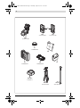 3
3
-
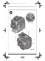 4
4
-
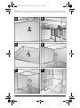 5
5
-
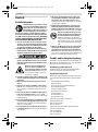 6
6
-
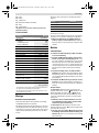 7
7
-
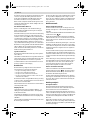 8
8
-
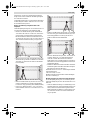 9
9
-
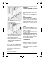 10
10
-
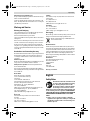 11
11
-
 12
12
-
 13
13
-
 14
14
-
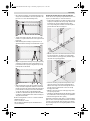 15
15
-
 16
16
-
 17
17
-
 18
18
-
 19
19
-
 20
20
-
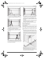 21
21
-
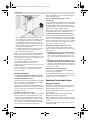 22
22
-
 23
23
-
 24
24
-
 25
25
-
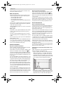 26
26
-
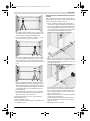 27
27
-
 28
28
-
 29
29
-
 30
30
-
 31
31
-
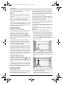 32
32
-
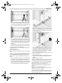 33
33
-
 34
34
-
 35
35
-
 36
36
-
 37
37
-
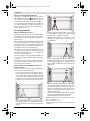 38
38
-
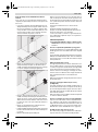 39
39
-
 40
40
-
 41
41
-
 42
42
-
 43
43
-
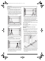 44
44
-
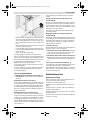 45
45
-
 46
46
-
 47
47
-
 48
48
-
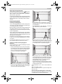 49
49
-
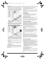 50
50
-
 51
51
-
 52
52
-
 53
53
-
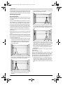 54
54
-
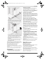 55
55
-
 56
56
-
 57
57
-
 58
58
-
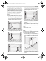 59
59
-
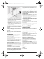 60
60
-
 61
61
-
 62
62
-
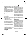 63
63
-
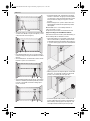 64
64
-
 65
65
-
 66
66
-
 67
67
-
 68
68
-
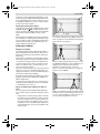 69
69
-
 70
70
-
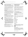 71
71
-
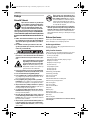 72
72
-
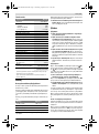 73
73
-
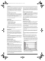 74
74
-
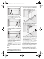 75
75
-
 76
76
-
 77
77
-
 78
78
-
 79
79
-
 80
80
-
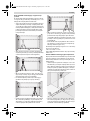 81
81
-
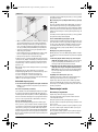 82
82
-
 83
83
-
 84
84
-
 85
85
-
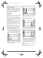 86
86
-
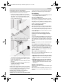 87
87
-
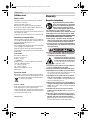 88
88
-
 89
89
-
 90
90
-
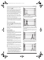 91
91
-
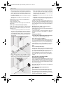 92
92
-
 93
93
-
 94
94
-
 95
95
-
 96
96
-
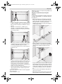 97
97
-
 98
98
-
 99
99
-
 100
100
-
 101
101
-
 102
102
-
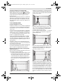 103
103
-
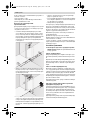 104
104
-
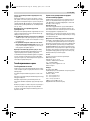 105
105
-
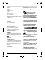 106
106
-
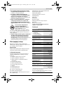 107
107
-
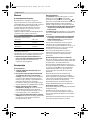 108
108
-
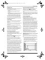 109
109
-
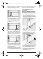 110
110
-
 111
111
-
 112
112
-
 113
113
-
 114
114
-
 115
115
-
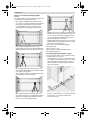 116
116
-
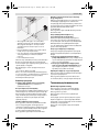 117
117
-
 118
118
-
 119
119
-
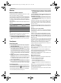 120
120
-
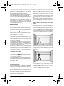 121
121
-
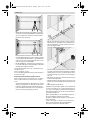 122
122
-
 123
123
-
 124
124
-
 125
125
-
 126
126
-
 127
127
-
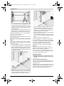 128
128
-
 129
129
-
 130
130
-
 131
131
-
 132
132
-
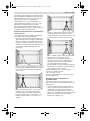 133
133
-
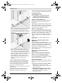 134
134
-
 135
135
-
 136
136
-
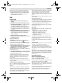 137
137
-
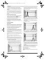 138
138
-
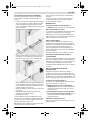 139
139
-
 140
140
-
 141
141
-
 142
142
-
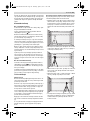 143
143
-
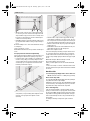 144
144
-
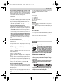 145
145
-
 146
146
-
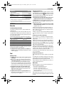 147
147
-
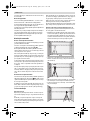 148
148
-
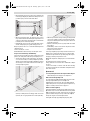 149
149
-
 150
150
-
 151
151
-
 152
152
-
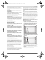 153
153
-
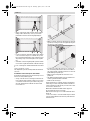 154
154
-
 155
155
-
 156
156
-
 157
157
-
 158
158
-
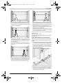 159
159
-
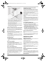 160
160
-
 161
161
-
 162
162
-
 163
163
-
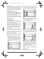 164
164
-
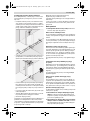 165
165
-
 166
166
-
 167
167
-
 168
168
-
 169
169
-
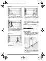 170
170
-
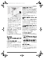 171
171
-
 172
172
-
 173
173
-
 174
174
-
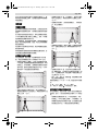 175
175
-
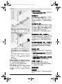 176
176
-
 177
177
-
 178
178
-
 179
179
-
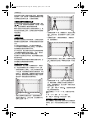 180
180
-
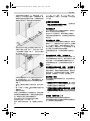 181
181
-
 182
182
-
 183
183
-
 184
184
-
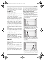 185
185
-
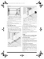 186
186
-
 187
187
-
 188
188
-
 189
189
-
 190
190
-
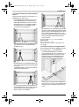 191
191
-
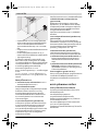 192
192
-
 193
193
-
 194
194
-
 195
195
-
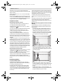 196
196
-
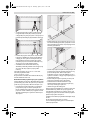 197
197
-
 198
198
-
 199
199
-
 200
200
-
 201
201
-
 202
202
-
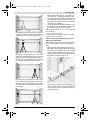 203
203
-
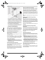 204
204
-
 205
205
-
 206
206
-
 207
207
-
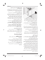 208
208
-
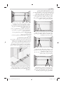 209
209
-
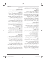 210
210
-
 211
211
-
 212
212
-
 213
213
-
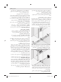 214
214
-
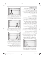 215
215
-
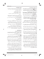 216
216
-
 217
217
-
 218
218


Lucrări conexe
-
Bosch GLL 3-80 C Manual de utilizare
-
Bosch GLL 3-80 Manual de utilizare
-
Bosch GLL 2-15 G Manual de utilizare
-
Bosch GLL 2-80 P Professional Original Instructions Manual
-
Bosch GLL 3-80 G Manual de utilizare
-
Bosch 466-1575 Manual de utilizare
-
-
Bosch GLL 2 Manualul proprietarului
-
Bosch GLL 3-50 Manualul proprietarului