Makita HR3011FC Manual de utilizare
- Categorie
- Ciocane rotative
- Tip
- Manual de utilizare

HR3011FC
HR3012FC
HR3001C
EN Combination Hammer INSTRUCTION MANUAL 9
PL Młotowiertarka z Opcją Kucia INSTRUKCJA OBSŁUGI 17
HU Fúrókalapács HASZNÁLATI KÉZIKÖNYV 26
SK Kombinované kladivo NÁVOD NA OBSLUHU 35
CS Kombinované kladivo NÁVOD K OBSLUZE 44
UK Перфоратор ІНСТРУКЦІЯ З
ЕКСПЛУАТАЦІЇ 53
RO Ansamblu percutor
multifuncţional MANUAL DE INSTRUCŢIUNI 63
DE Kombi-Hammer BETRIEBSANLEITUNG 72

1
Fig.1
1
Fig.2
AB
1
Fig.3
1
32
Fig.4
2
4
1
3
Fig.5
1
2
Fig.6
1
Fig.7
1
Fig.8
2

1
Fig.9
1
Fig.10
1
Fig.11
1
2
Fig.12
1
Fig.13
1
2
Fig.14
1
Fig.15
1 2
4
3
Fig.16
3

1
Fig.17
2
3
1
Fig.18
2
111
Fig.19
1
2
Fig.20
Fig.21
2
111
Fig.22
1
2
Fig.23
Fig.24
4

1
Fig.25
Fig.26
2
1
4
3
Fig.27
1
Fig.28
1
Fig.29
1
Fig.30
5

2
1
Fig.31
1
A
Fig.32
1
2
Fig.33
1
Fig.34
1
Fig.35
Fig.36
1
Fig.37
6

1
2
Fig.38
2
1
Fig.39
Fig.40
Fig.41
2
1
Fig.42
1
2
Fig.43
Fig.44
Fig.45
7

1
2
Fig.46
8

9ENGLISH
ENGLISH (Original instructions)
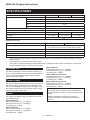
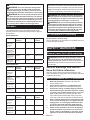
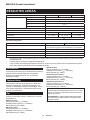
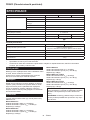
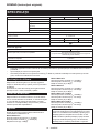
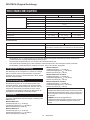
SPECIFICATIONS
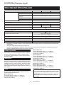
Model: HR3011FC HR3012FC HR3001C
Capacities Concrete 30 mm
Core bit 80 mm
Diamond core bit (dry type) 80 mm
Steel 13 mm
Wood 32 mm
No load speed 0 - 840 min-1
Blows per minute 0 - 4,500 min-1
Overall length 369 mm 386 mm 369 mm
Net weight 4.4 - 4.8 kg 4.5 - 4.7 kg 4.1 - 4.5 kg
Safety class /II
Optional accessory
Model: DX10 (For HR3011FC) DX11 (For HR3012FC)
Applicable workpiece and workmode for concrete drilling only
(not for metal or wood, and not for core drilling or chiseling)
Suction performance 0.35 l/min
Operating stroke Up to 190 mm
Suitable drill bit Up to 265 mm
Net weight 1.2 kg
• Duetoourcontinuingprogramofresearchanddevelopment,thespecicationshereinaresubjecttochange
without notice.
• Specicationsmaydierfromcountrytocountry.
• Theweightmaydierdependingontheattachment(s).Thelightestandheaviestcombination,accordingto
EPTA-Procedure 01/2014, are shown in the table.
Intended use
The tool is intended for hammer drilling and drilling in
brick, concrete and stone as well as for chiselling work.
It is also suitable for drilling without impact in wood,
metal, ceramic and plastic.
Power supply
The tool should be connected only to a power supply of
the same voltage as indicated on the nameplate, and
can only be operated on single-phase AC supply. They
are double-insulated and can, therefore, also be used
from sockets without earth wire.
Noise
The typical A-weighted noise level determined accord-
ing to EN60745-2-6:
Model HR3011FC
Sound pressure level (LpA) : 94 dB(A)
Sound power level (LWA) : 105 dB (A)
Uncertainty (K) : 3 dB(A)
Model HR3012FC
Sound pressure level (LpA) : 93 dB(A)
Sound power level (LWA) : 104 dB (A)
Uncertainty (K) : 3 dB(A)
Model HR3001C
Sound pressure level (LpA) : 94 dB(A)
Sound power level (LWA) : 105 dB (A)
Uncertainty (K) : 3 dB(A)
Model HR3011FC with DX10
Sound pressure level (LpA) : 96 dB(A)
Sound power level (LWA) : 107 dB (A)
Uncertainty (K) : 3 dB(A)
Model HR3012FC with DX11
Sound pressure level (LpA) : 94 dB(A)
Sound power level (LWA) : 105 dB (A)
Uncertainty (K) : 3 dB(A)
NOTE: The declared noise emission value(s) has
been measured in accordance with a standard test
method and may be used for comparing one tool with
another.
NOTE: The declared noise emission value(s)
may also be used in a preliminary assessment of
exposure.

10 ENGLISH
WARNING: Wear ear protection.
WARNING:
The noise emission during actual
use of the power tool can dier from the declared
value(s) depending on the ways in which the tool is
used especially what kind of workpiece is processed.
WARNING:
Be sure to identify safety measures
to protect the operator that are based on an estima-
tion of exposure in the actual conditions of use (tak-
ing account of all parts of the operating cycle such
as the times when the tool is switched o and when
it is running idle in addition to the trigger time).
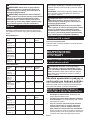
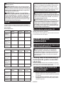
Vibration
The following table shows the vibration total value
(tri-axial vector sum) determined according to applica-
ble standard.
Model HR3011FC
Work mode Vibration
emission
Uncertainty (K)
Applicable
standard
Hammer
drilling into
concrete
(ah, HD)
9.5 m/s21.5 m/s2EN60745-2-6
Hammer
drilling into
concrete with
DX10 (ah, HD)
9.5 m/s21.5 m/s2EN60745-2-6
Chiselling func-
tion with side
grip (ah, Cheq)
6.0 m/s21.5 m/s2EN60745-2-6
Drilling into
metal (ah, D)
5.5 m/s21.5 m/s2EN62841-2-1
Model HR3012FC
Work mode Vibration
emission
Uncertainty (K)
Applicable
standard
Hammer
drilling into
concrete
(ah, HD)
9.5 m/s21.5 m/s2EN60745-2-6
Hammer
drilling into
concrete with
DX11 (ah, HD)
8.0 m/s21.5 m/s2EN60745-2-6
Chiselling func-
tion with side
grip (ah, Cheq)
5.5 m/s21.5 m/s2EN60745-2-6
Drilling into
metal (ah, D)
6.0 m/s21.5 m/s2EN62841-2-1
Model HR3001C
Work mode Vibration
emission
Uncertainty (K)
Applicable
standard
Hammer
drilling into
concrete
(ah, HD)
13.5 m/s21.5 m/s2EN60745-2-6
Chiselling func-
tion with side
grip (ah, Cheq)
11.0 m/s21.5 m/s2EN60745-2-6
Drilling into
metal (ah, D)
6.0 m/s21.5 m/s2EN62841-2-1
NOTE: The declared vibration total value(s) has been
measured in accordance with a standard test method
and may be used for comparing one tool with another.
NOTE: The declared vibration total value(s) may also
be used in a preliminary assessment of exposure.
WARNING: The vibration emission during actual
use of the power tool can dier from the declared val-
ue(s) depending on the ways in which the tool is used
especially what kind of workpiece is processed.
WARNING:
Be sure to identify safety measures
to protect the operator that are based on an estima-
tion of exposure in the actual conditions of use (tak-
ing account of all parts of the operating cycle such
as the times when the tool is switched o and when
it is running idle in addition to the trigger time).
EC Declaration of Conformity
For European countries only
The EC declaration of conformity is included as Annex A
to this instruction manual.
SAFETY WARNINGS
General power tool safety warnings
WARNING: Read all safety warnings, instruc-
tions, illustrations and specications provided
with this power tool. Failure to follow all instructions
listedbelowmayresultinelectricshock,reand/or
seriousinjury.
Save all warnings and instruc-
tions for future reference.
The term "power tool" in the warnings refers to your
mains-operated (corded) power tool or battery-operated
(cordless) power tool.
ROTARY HAMMER SAFETY WARNINGS
1. Wear ear protectors. Exposure to noise can
cause hearing loss.
2. Use auxiliary handle(s), if supplied with the
tool.Lossofcontrolcancausepersonalinjury.
3.
Hold power tool by insulated gripping surfaces,
when performing an operation where the cutting
accessory may contact hidden wiring or its own
cord. Cutting accessory contacting a "live" wire
may make exposed metal parts of the power tool
"live" and could give the operator an electric shock.
4.
Wear a hard hat (safety helmet), safety glasses and/
or face shield. Ordinary eye or sun glasses are NOT
safety glasses. It is also highly recommended that
you wear a dust mask and thickly padded gloves.
5.
Be sure the bit is secured in place before operation.
6.
Under normal operation, the tool is designed to
produce vibration. The screws can come loose
easily, causing a breakdown or accident. Check
tightness of screws carefully before operation.

11 ENGLISH
7.
In cold weather or when the tool has not been used for a
long time, let the tool warm up for a while by operating it
under no load. This will loosen up the lubrication. Without
proper warm-up, hammering operation is dicult.
8.
Always be sure you have a rm footing. Be sure no
one is below when using the tool in high locations.
9. Hold the tool rmly with both hands.
10. Keep hands away from moving parts.
11. Do not leave the tool running. Operate the tool
only when hand-held.
12.
Do not point the tool at any one in the area when operat-
ing. The bit could y out and injure someone seriously.
13.
Do not touch the bit, parts close to the bit, or
workpiece immediately after operation; they may
be extremely hot and could burn your skin.
14.
Some material contains chemicals which may be
toxic. Take caution to prevent dust inhalation and
skin contact. Follow material supplier safety data.
15. Do not touch the power plug with wet hands.
SAVE THESE INSTRUCTIONS.
WARNING:
DO NOT let comfort or familiarity with
product (gained from repeated use) replace strict adher-
ence to safety rules for the subject product. MISUSE or
failure to follow the safety rules stated in this instruc-
tion manual may cause serious personal injury.
FUNCTIONAL
DESCRIPTION
CAUTION: Always be sure that the tool is
switched o and unplugged before adjusting or
checking function on the tool.
Switch action
CAUTION: Before plugging in the tool, always
check to see that the switch trigger actuates
properly and returns to the "OFF" position when
released.
To start the tool, simply pull the switch trigger. Tool
speed is increased by increasing pressure on the switch
trigger. Release the switch trigger to stop.
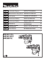
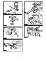
►Fig.1: 1. Switch trigger
Lighting up the front lamp
For HR3011FC, HR3012FC only
CAUTION: Do not look in the light or see the
source of light directly.
To turn on the lamp, pull the switch trigger. Release the
switchtriggertoturnito.
►Fig.2: 1. Lamp
NOTE:Useadryclothtowipethedirtothelensof
the lamp. Be careful not to scratch the lens of lamp, or
it may lower the illumination.
Reversing switch action
CAUTION: Always check the direction of
rotation before operation.
CAUTION: Use the reversing switch only after
the tool comes to a complete stop. Changing the
direction of rotation before the tool stops may dam-
age the tool.
NOTICE: When changing the direction of rota-
tion, be sure to fully set the reversing switch to A
side or B side. Otherwise, when the switch trigger is
pulled, the motor may not rotate or the tool may not
work properly.
This tool has a reversing switch to change the direc-
tion of rotation. Move the reversing switch lever to the
position A side for clockwise rotation or to the position B
side for counterclockwise rotation.
►Fig.3: 1. Reversing switch lever
Changing the quick change chuck
for SDS-plus
For HR3012FC only
The quick change chuck for SDS-plus can be easily
exchanged for the quick change drill chuck.
Removing the quick change chuck
for SDS-plus
CAUTION: Before removing the quick change
chuck for SDS-plus, be sure to remove the bit.
Grasp the change cover of the quick change chuck
for SDS-plus and turn in the direction of the arrow
until the change cover line moves from the symbol
to the symbol. Pull forcefully in the direction of the
arrow.
►Fig.4: 1. Quick change chuck for SDS-plus
2. Change cover 3. Change cover line
Installing the quick change drill
chuck
Check the line of the quick change drill chuck shows
the symbol. Grasp the change cover of the quick
change drill chuck and set the line to the symbol.
Place the quick change drill chuck on the spindle of the
tool. Grasp the change cover of the quick change drill
chuck and turn the change cover line to the symbol
until a click can clearly be heard.
►Fig.5: 1. Quick change drill chuck 2. Spindle
3. Change cover line 4. Change cover

12 ENGLISH
Selecting the action mode
NOTICE:
Do not rotate the action mode changing
knob when the tool is running. The tool will be damaged.
NOTICE: To avoid rapid wear on the mode
change mechanism, be sure that the action mode
changing knob is always positively located in one
of the three action mode positions.
Rotation with hammering
For drilling in concrete, masonry, etc., rotate the action
mode changing knob to the symbol. Use a tungsten-
carbide tipped bit (optional accessory).
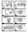
►Fig.6: 1. Rotation with hammering 2. Action mode
changing knob
Rotation only
For drilling in wood, metal or plastic materials, rotate
the action mode changing knob to the symbol. Use a
twist drill bit or wood drill bit.
►Fig.7: 1. Rotation only
Hammering only
For chipping, scaling or demolition operations, rotate
the action mode changing knob to the symbol. Use a
bull point, cold chisel, scaling chisel, etc.
►Fig.8: 1. Hammering only
Torque limiter
NOTICE: As soon as the torque limiter actuates,
switch o the tool immediately. This will help pre-
vent premature wear of the tool.
NOTICE: Drill bits such as hole saw, which tend
to pinch or catch easily in the hole, are not appro-
priate for this tool. This is because they will cause
the torque limiter to actuate too frequently.
The torque limiter will actuate when a certain torque level
is reached. The motor will disengage from the output
shaft. When this happens, the drill bit will stop turning.
Electronic function
The tool is equipped with the electronic functions for easy operation.
• Constant speed control
The speed control function provides the constant
rotation speed regardless of load conditions.
Air duct
For HR3011FC, HR3012FC only
CAUTION: Do not put your nger into the air
duct or do not insert any other object into the air
duct.Otherwiseyoumaygetinjuredorthetoolmay
get damaged.
The air duct is to connect to the dust collection system.
When using the dust collection system, read the section
about the dust collection system.
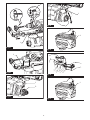
►Fig.9: 1. Air duct
ASSEMBLY
CAUTION: Always be sure that the tool is
switched o and unplugged before carrying out
any work on the tool.
Side grip (auxiliary handle)
CAUTION: Always use the side grip to ensure
safe operation.
CAUTION: After installing or adjusting the
side grip, make sure that the side grip is rmly
secured.
To install the side grip, follow the steps below.
1. Loosen the thumb screw on the side grip.
►Fig.10: 1. Thumb screw
2. Attach the side grip while pressing the thumb
screwsothatthegroovesonthegriptintheprotru-
sions on the tool barrel.
►Fig.11: 1. Thumb screw
3. Tighten the thumb screw to secure the grip. The
gripcanbexedatdesiredangle.
Grease
Coat the shank end of the drill bit beforehand with a
small amount of grease (about 0.5 - 1 g).
This chuck lubrication assures smooth action and lon-
ger service life.
Installing or removing drill bit
Clean the shank end of the drill bit and apply grease
before installing the drill bit.
►Fig.12: 1. Shank end 2. Grease
Insert the drill bit into the tool. Turn the drill bit and push
it in until it engages.
After installing the drill bit, always make sure that the
drill bit is securely held in place by trying to pull it out.
►Fig.13: 1. Drill bit
To remove the drill bit, pull the chuck cover down all the
way and pull the drill bit out.
►Fig.14: 1. Drill bit 2. Chuck cover
Chisel angle (when chipping,
scaling or demolishing)
The chisel can be secured at the desired angle. To
change the chisel angle, rotate the action mode chang-
ing knob to the O symbol. Turn the chisel to the desired
angle.
►Fig.15: 1. Action mode changing knob
Rotate the action mode changing knob to the sym-
bol. Then make sure that the chisel is securely held in
place by turning it slightly.

13 ENGLISH
Depth gauge
The depth gauge is convenient for drilling holes of uniform depth.
Press and hold the lock button, and then insert the
depth gauge into the hex hole. Make sure that the
toothed side of the depth gauge faces the marking.
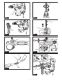
►Fig.16: 1. Depth gauge 2. Lock button 3. Marking
4. Toothed side
Adjustthedepthgaugebymovingitbackandforth
whilepressingthelockbutton.Aftertheadjustment,
release the lock button to lock the depth gauge.
NOTE: Make sure that the depth gauge does not
touch the main body of the tool when attaching it.
Dust cup
Optional accessory
Use the dust cup to prevent dust from falling over the
tool and on yourself when performing overhead drilling
operations. Attach the dust cup to the bit as shown in
thegure.Thesizeofbitswhichthedustcupcanbe
attached to is as follows.
Model Bit diameter
Dust cup 5 6 mm - 14.5 mm
Dust cup 9 12 mm - 16 mm
►Fig.17: 1. Dust cup
Dust cup set
Optional accessory
For Models HR3011FC, HR3001C
NOTICE: When using the dust cup set in
HR3011FC, HR3001C, the spacer is also requied.
Before installing the dust cup set, remove the bit from
the tool if installed.
Attach the spacer to the dust cup set. symbol on the
dust cup is aligned with the groove in the spacer.
►Fig.18: 1. Spacer 2. symbol 3. Groove
Install the dust cup set with the spacer on the tool so
that the symbol on the dust cup is aligned with the
groove in the tool.
►Fig.19: 1. symbol 2. Groove
To remove the dust cup set, remove the bit while pulling
the chuck cover in the direction of the arrow.
►Fig.20: 1. Bit 2. Chuck cover
Hold the spacer and pull it out.
►Fig.21
For Model HR3012FC
Before installing the dust cup set, remove the bit from
the tool if installed.
Install the dust cup set on the tool so that the sym-
bol on the dust cup is aligned with the groove in the tool.
►Fig.22: 1. symbol 2. Groove
To remove the dust cup set, remove the bit while pulling
the chuck cover in the direction of the arrow.
►Fig.23: 1. Bit 2. Chuck cover
Hold the root of dust cup and pull it out.
►Fig.24
NOTE: If you connect a vacuum cleaner to the dust
cup set, remove the dust cap before connecting it.
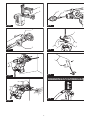
►Fig.25: 1. Dust cap
NOTE:Ifthecapcomesofromthedustcup,attach
it with its printed side facing up so that groove on the
captsintheinsideperipheryoftheattachment.
►Fig.26
Tool hanger
Optional accessory
WARNING: Do not use damaged tool hanger
and screw.
WARNING: Use the screw provided with the
tool hanger only.
WARNING: Before using the tool hanger,
check for damages, cracks or deformations, and
make sure that the screw is tightened.
CAUTION: Install or remove the tool hanger
on a stable table or surface.
The tool hanger is intended for connecting the lanyard
(tether strap). To install the tool hanger to the tool,
follow the steps below.
1. Disconnect the plug from the power source.
2. Inserttheprojectionsofthetoolhangerintothe
holes on the tool.
3. Tightenthescrewsrmly.
►Fig.27: 1. Tool hanger 2. Hole 3.Projection
4. Screw
DUST COLLECTION
SYSTEM
For HR3011FC, HR3012FC only
Optional accessory
The dust collection system is designed to collect dusts
eectivelywhentheconcretedrillingoperation.
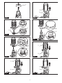
►Fig.28: 1. Dust collection system
CAUTION: Make sure that the tool is switched
o and unplugged before carrying out any work
on the tool. Failure to do so may result in personal
injuryfromaccidentalstart-up.
CAUTION: Always attach the lter to the
dust collection system. Failure to do so cause dust
inhalation.
CAUTION: Check that the lter is not dam-
aged. Failure to do so may cause dust inhalation.

14 ENGLISH
NOTICE: Do not use the dust collection system
for core drilling or chiseling. The dust collection
system is intended for drilling only.
NOTICE: Do not use the dust collection system
for metal or wood. The dust collection system is
intended for concrete only.
NOTICE: Do not use the dust collection system
for drilling in wet concrete or use this system
in wet environment. Failure to do so may cause
malfunction.
NOTE: The dust collection system collects the gener-
ated dust at a considerable rate, but not all dust can
be collected.
Installing or removing the dust
collection system
NOTICE: Before installing the dust collection
system, clean the joint parts of the tool and the
dust collection system.
Foreignmattersonthejointpartsmaycauseitdi-
cult to install the dust collection system. Particularly
the foreign matters on the electrical interface may
cause malfunction.
If any dust remains on the air duct, the dust comes
intothetoolandcausesjamintheairoworbreak-
age of the tool.
Hook the dust collection system on the tool, and then
insert the dust collection system all the way, until it locks
in place with a little double click.
After that, make sure that the dust collection system is
securely installed.
►Fig.29: 1. Air duct
When removing the dust collection system, press the
lock-obutton.
►Fig.30: 1.Lock-obutton
Adjusting the nozzle position of the
dust collection system
CAUTION: Do not point the nozzle at yourself
or others when releasing the nozzle by pushing
the guide adjustment button.
Pushintheguidewhilepushingtheguideadjustment
button,andthenreleasetheguideadjustmentbuttonat
the desired position.
►Fig.31: 1. Guide 2.Guideadjustmentbutton
Adjusting the drilling depth of the
dust collection system
Slidethedepthadjustmentbuttontothedesiredposi-
tion while pushing it. The distance (A) is the drilling
depth.
►Fig.32: 1.Depthadjustmentbutton
Beating dust on the lter
CAUTION: Do not turn the dial on the dust
case while the dust case is removed from the
dust collection system. Doing so may cause dust
inhalation.
CAUTION: Always switch o the tool when
turning the dial on the dust case. Turning the dial
while the tool is running may result in the loss of
control of the tool.
Bybeatingthedustonthelterinsidethedustcase,
youcankeepthevacuumeciencyandalsoreduce
the number of times to dispose of the dust.
Turn the dial on the dust case three times after col-
lecting every 50,000 mm3 of dust or when you feel the
vacuum performance declined.
NOTE: 50,000 mm3 of dust equivalents to drilling 10
holesofø10mmand14mmdepth(2holesofø65″
and3/8″depth).
►Fig.33: 1. Dust case 2. Dial
Disposing of dust
CAUTION:
Wear dust mask when disposing of dust.
CAUTION:
Empty the dust case regularly before the
dust case becomes full. Failure to do so may decrease the
dust collection performance, and then cause dust inhalation.
CAUTION: Replace the lter with new one
after approximately 200 times of dust fulllment
as a guide.Acloggedlterdecreasesdustcollection
performance, and then cause dust inhalation.
NOTICE: When cleaning the lter, tap the case
of the lter gently by hand to remove dust. Do not
tap the lter directly; touch the lter with brush
or similar; or blow compressed air on the lter.
Doing so may damage the lter.
1. Remove the dust case while pressing down the
lever of the dust case.
►Fig.34: 1. Lever
2. Open the cover of the dust case.
►Fig.35: 1. Cover
3. Disposeofthedust,andthencleanthelter.
►Fig.36
Replacing lter of dust case
1. Remove the dust case while pressing down the
lever of the dust case. (Refer to the section for dispos-
ing of dust.)
2. Opentheltercoverofthedustcase.
►Fig.37: 1. Filter cover
3. Removethelterfromtheltercase.
►Fig.38: 1. Filter 2. Filter case
4. Attachanewltertotheltercase,andthen
attachtheltercover.
5. Close the cover of the dust case, and then attach
the dust case to the dust collection system.

15 ENGLISH
Replacing sealing cap
If the sealing cap is worn out, the performance of the
dust collection decreases. Replace it if it is worn out.
Remove the sealing cap, and then attach a new one
with its protrusion facing upward.
►Fig.39: 1. Protrusion 2. Sealing cap
OPERATION
CAUTION: Always use the side grip (auxiliary
handle) and rmly hold the tool by both side grip
and switch handle during operations.
CAUTION: Always make sure that the work-
piece is secured before operation.
CAUTION: Do not pull the tool out forcibly
even the bit gets stuck. Loss of control may
cause injury.
CAUTION: For HR3011FC, HR3012FC only
Before using the dust collection system with the
tool, read the section about the dust collection
system.
►Fig.40
Hammer drilling operation
CAUTION: There is tremendous and sudden
twisting force exerted on the tool/drill bit at the time of
hole break-through, when the hole becomes clogged
with chips and particles, or when striking reinforcing
rods embedded in the concrete. Always use the side
grip (auxiliary handle) and rmly hold the tool by
both side grip and switch handle during opera-
tions. Failure to do so may result in the loss of control
ofthetoolandpotentiallysevereinjury.
Set the action mode changing knob to the symbol.
Position the drill bit at the desired location for the hole,
then pull the switch trigger. Do not force the tool. Light
pressure gives best results. Keep the tool in position
and prevent it from slipping away from the hole.
Do not apply more pressure when the hole becomes
clogged with chips or particles. Instead, run the tool at
an idle, then remove the drill bit partially from the hole.
By repeating this several times, the hole will be cleaned
out and normal drilling may be resumed.
NOTE: Eccentricity in the drill bit rotation may occur
while operating the tool with no load. The tool auto-
matically centers itself during operation. This does not
aectthedrillingprecision.
Chipping/Scaling/Demolition
Set the action mode changing knob to the symbol.
Holdthetoolrmlywithbothhands.Turnthetoolon
and apply slight pressure on the tool so that the tool will
not bounce around, uncontrolled.
Pressingveryhardonthetoolwillnotincreasetheeciency.
►Fig.41
Drilling in wood or metal
CAUTION: Hold the tool rmly and exert care
when the drill bit begins to break through the
workpiece. There is a tremendous force exerted on
the tool/drill bit at the time of hole break through.
CAUTION: A stuck drill bit can be removed
simply by setting the reversing switch to reverse
rotation in order to back out. However, the tool
may back out abruptly if you do not hold it rmly.
CAUTION: Always secure workpieces in a
vise or similar hold-down device.
NOTICE: Never use “rotation with hammering”
when the drill chuck is installed on the tool. The
drill chuck may be damaged.
Also,thedrillchuckwillcomeowhenreversingthe
tool.
NOTICE: Pressing excessively on the tool will
not speed up the drilling. In fact, this excessive
pressure will only serve to damage the tip of your drill
bit, decrease the tool performance and shorten the
service life of the tool.
Set the action mode changing knob to the symbol.
For Models HR3011FC, HR3001C
Optional accessory
Attach the chuck adapter to a keyless drill chuck to
which1/2"-20sizescrewcanbeinstalled,andthen
install them to the tool. When installing it, refer to the
section “Installing or removing drill bit”.
►Fig.42: 1. Keyless drill chuck 2. Chuck adapter
For Model HR3012FC
Use the quick change drill chuck as standard equip-
ment. When installing it, refer to "changing the quick
change chuck for SDS-plus".
Hold the ring and turn the sleeve counterclockwise to
openthechuckjaws.Placethebitinthechuckasfaras
itwillgo.Holdtheringrmlyandturnthesleeveclock-
wise to tighten the chuck.
►Fig.43: 1. Sleeve 2. Ring
To remove the bit, hold the ring and turn the sleeve
counterclockwise.
Diamond core drilling
NOTICE: If performing diamond core drilling
operations using “rotation with hammering”
action, the diamond core bit may be damaged.
When performing diamond core drilling opera-
tions, always set the action mode changing knob to
the position to use "rotation only" action.
Blow-out bulb
Optional accessory
After drilling the hole, use the blow-out bulb to clean the
dust out of the hole.
►Fig.44

16 ENGLISH
Using dust cup set
Optional accessory
Fit the dust cup set against the ceiling when operating the tool.
►Fig.45
NOTICE: Do not use the dust cup set when drill-
ing in metal or similar. It may damage the dust
cup set due to the heat produced by small metal
dust or similar.
NOTICE: Do not install or remove the dust cup
set with the drill bit installed in the tool. It may
damage the dust cup set and cause dust leak.
Connecting lanyard (tether strap) to
tool hanger
Safety warnings specic for use at height
Read all safety warnings and instructions. Failure to follow
thewarningsandinstructionsmayresultinseriousinjury.
1. Always keep the tool tethered when working
"at height". Maximum lanyard length is 2 m.
The maximum permissible fall height for lan-
yard (tether strap) must not exceed 2 m.
2. Use only with lanyards appropriate for this tool
type and rated for at least 7.5 kg.
3. Do not anchor the tool lanyard to anything on
your body or on movable components. Anchor
the tool lanyard to a rigid structure that can
withstand the forces of a dropped tool.
4. Make sure the lanyard is properly secured at
each end prior to use.
5. Inspect the tool and lanyard before each use
for damage and proper function (including
fabric and stitching). Do not use if damaged or
not functioning properly.
6. Do not wrap lanyards around or allow them to
come in contact with sharp or rough edges.
7.
Fasten the other end of the lanyard outside the
working area so that a falling tool is held securely.
8.
Attach the lanyard so that the tool will move away
from the operator if it falls. Dropped tools will swing on
thelanyard,whichcouldcauseinjuryorlossofbalance.
9. Do not use near moving parts or running
machinery. Failure to do so may result in a crush
orentanglementhazard.
10. Do not carry the tool by the attachment device
or the lanyard.
11. Only transfer the tool between your hands
while you are properly balanced.
12. Do not attach lanyards to the tool in a way that
keeps switches or trigger-lock (if supplied)
from operating properly.
13. Avoid getting tangled in the lanyard.
14.
Keep lanyard away from the drilling area of the tool.
15.
Use multi-action and screw gate type carabineers.
Do not use single action spring clip carabineers.
16. In the event the tool is dropped, it must be
tagged and removed from service, and should
be inspected by a Makita Factory or Authorized
Service Center.
►Fig.46: 1. Tool hanger 2. Lanyard (tether strap)
MAINTENANCE
CAUTION: Always be sure that the tool is
switched o and unplugged before attempting to
perform inspection or maintenance.
NOTICE: Never use gasoline, benzine, thinner,
alcohol or the like. Discoloration, deformation or
cracks may result.
To maintain product SAFETY and RELIABILITY,
repairs,anyothermaintenanceoradjustmentshould
beperformedbyMakitaAuthorizedorFactoryService
Centers, always using Makita replacement parts.
OPTIONAL
ACCESSORIES
CAUTION: These accessories or attachments
are recommended for use with your Makita tool
specied in this manual. The use of any other
accessories or attachments might present a risk of
injurytopersons.Onlyuseaccessoryorattachment
for its stated purpose.
If you need any assistance for more details regard-
ing these accessories, ask your local Makita Service
Center.
• Carbide-tipped drill bits (SDS-Plus carbide-tipped
bits)
• Core bit
• Bull point
• Diamond core bit
• Cold chisel
• Scaling chisel
• Grooving chisel
• Chuck adapter
• Keyless drill chuck
• Bit grease
• Depth gauge
• Blow-out bulb
• Dust cup
• Dust cup set
• Spacer (for HR3011FC, HR3001C)
• Dust collection system (for HR3011FC,
HR3012FC)
• Safety goggles
• Tool hanger
NOTE: Some items in the list may be included in the
tool package as standard accessories. They may
dierfromcountrytocountry.

17 POLSKI
POLSKI (Instrukcja oryginalna)
DANE TECHNICZNE
Model: HR3011FC HR3012FC HR3001C
Zakresy wiercenia Beton 30 mm
Wiertłokoronowe 80 mm
Diamentowewiertłokoronowe(suche)
80 mm
Stal 13 mm
Drewno 32 mm
Prędkośćbezobciążenia 0 – 840 min-1
Liczbaudarównaminutę 0 – 4 500 min-1
Długośćcałkowita 369 mm 386 mm 369 mm
Masa netto 4,4 – 4,8 kg 4,5–4,7 kg 4,1 – 4,5 kg
Klasabezpieczeństwa /II
Wyposażenie dodatkowe
Model:
DX10 (dotyczy modelu HR3011FC) DX11 (dotyczy modelu HR3012FC)
Obrabianyelementitrybpracymożliwedozastosowania tylko wiercenie w betonie
(niedotyczymetalulubdrewnaaniwiercenialubkuciakoronowego)
Wydajnośćssania 0,35 l/min
Skokroboczy Maks. 190 mm
Odpowiedniewiertło Maks. 265 mm
Masa netto 1,2 kg
• Wzwiązkuzestaleprowadzonymprzeznasząrmęprogramembadawczo-rozwojowymniniejszedanemogą
uleczmianombezwcześniejszegopowiadomienia.
• Danetechnicznemogąróżnićsięwzależnościodkraju.
• Wysokośćmożebyćróżnawzależnościodosprzętu.Wtabelizostałaprzedstawionanajlżejszainajcięższa
konguracjazgodniezprocedurąEPTA01/2014.
Przeznaczenie
Narzędziejestprzeznaczonedowierceniaudarowegooraz
wierceniawcegle,betonieikamieniu,atakżedopodkuwania.
Nadajesięrównieżdowierceniawdrewnie,metalu,
ceramiceitworzywachsztucznychbezużyciaudaru.
Zasilanie
Narzędziewolnopodłączaćtylkodoźródełzasilaniao
napięciuzgodnymznapięciempodanymnatabliczce
znamionowej.Możnajezasilaćwyłączniejednofazo-
wymprądemprzemiennym.Narzędziemapodwójną
izolację,dlategoteżmożnajezasilaćzgniazdaelek-
trycznegobezuziemienia.
Hałas
TypowyrównoważnypoziomdźwiękuAokreślonyw
oparciuonormęEN60745-2-6:
Model HR3011FC
Poziomciśnieniaakustycznego(LpA): 94 dB(A)
Poziommocyakustycznej(LWA): 105 dB (A)
Niepewność(K):3dB(A)
Model HR3012FC
Poziomciśnieniaakustycznego(LpA): 93 dB(A)
Poziommocyakustycznej(LWA): 104 dB (A)
Niepewność(K):3dB(A)
Model HR3001C
Poziomciśnieniaakustycznego(LpA): 94 dB(A)
Poziommocyakustycznej(LWA): 105 dB (A)
Niepewność(K):3dB(A)
Model HR3011FC z DX10
Poziomciśnieniaakustycznego(LpA): 96 dB(A)
Poziommocyakustycznej(LWA): 107 dB (A)
Niepewność(K):3dB(A)
Model HR3012FC z DX11
Poziomciśnieniaakustycznego(LpA): 94 dB (A)
Poziommocyakustycznej(LWA): 105 dB (A)
Niepewność(K):3dB(A)
WSKAZÓWKA:Deklarowanawartośćemisjihałasu
zostałazmierzonazgodniezestandardowąmetodą
testowąimożnająwykorzystaćdoporównywania
narzędzi.
WSKAZÓWKA:Deklarowanąwartośćemisjihałasu
możnatakżewykorzystaćwewstępnejocenie
narażenia.

18 POLSKI
OSTRZEŻENIE: Nosić ochronniki słuchu.
OSTRZEŻENIE:
Poziom hałasu wytwarzanego
podczas rzeczywistego użytkowania elektronarzę-
dzia może się różnić od wartości deklarowanej w
zależności od sposobu użytkowania narzędzia, a w
szczególności od rodzaju obrabianego elementu.
OSTRZEŻENIE:
W oparciu o szacowane narażenie
w rzeczywistych warunkach użytkowania należy określić
środki bezpieczeństwa w celu zapewnienia ochrony ope-
ratora (uwzględniając wszystkie elementy cyklu działania,
tj. czas, kiedy narzędzie jest wyłączone i kiedy pracuje na
biegu jałowym, a także czas, kiedy jest włączone).
Drgania
Poniższatabelaprzedstawiawartośćpoziomudrgań
(sumawektoróww3osiach)określonązgodniezobo-
wiązującąnormą.
Model HR3011FC
Tryb pracy Emisja drgań
Niepewność (K)
Obowiązująca
norma
Wiercenie
udarowe w
betonie (ah, HD)
9,5 m/s21,5 m/s2EN60745-2-6
Wiercenie uda-
rowe w betonie
zzastosowa-
niem DX10
(ah, HD)
9,5 m/s21,5 m/s2EN60745-2-6
Podkuwaniez
uchwytembocz-
nym (ah, Cheq)
6,0 m/s21,5 m/s2EN60745-2-6
Wiercenie w
metalu (ah, D)
5,5 m/s21,5 m/s2EN62841-2-1
Model HR3012FC
Tryb pracy Emisja drgań
Niepewność (K)
Obowiązująca
norma
Wiercenie
udarowe w
betonie (ah, HD)
9,5 m/s21,5 m/s2EN60745-2-6
Wiercenie uda-
rowe w betonie
zzastosowa-
niem DX11
(ah, HD)
8,0 m/s21,5 m/s2EN60745-2-6
Podkuwaniez
uchwytembocz-
nym (ah, Cheq)
5,5 m/s21,5 m/s2EN60745-2-6
Wiercenie w
metalu (ah, D)
6,0 m/s21,5 m/s2EN62841-2-1
Model HR3001C
Tryb pracy Emisja drgań
Niepewność (K)
Obowiązująca
norma
Wiercenie
udarowe w
betonie (ah, HD)
13,5 m/s21,5 m/s2EN60745-2-6
Podkuwaniez
uchwytembocz-
nym (ah, Cheq)
11,0 m/s21,5 m/s2EN60745-2-6
Wiercenie w
metalu (ah, D)
6,0 m/s21,5 m/s2EN62841-2-1
WSKAZÓWKA:
Deklarowanawartośćpoziomudrgań
zostałazmierzonazgodniezestandardowąmetodątestową
imożnająwykorzystaćdoporównywanianarzędzi.
WSKAZÓWKA:
Deklarowanąwartośćpoziomudrgań
możnatakżewykorzystaćwewstępnejocenienarażenia.
OSTRZEŻENIE: Drgania wytwarzane pod-
czas rzeczywistego użytkowania elektronarzędzia
mogą się różnić od wartości deklarowanej w
zależności od sposobu użytkowania narzędzia,
a w szczególności od rodzaju obrabianego
elementu.
OSTRZEŻENIE: W oparciu o szacowane
narażenie w rzeczywistych warunkach użytkowa-
nia należy określić środki bezpieczeństwa w celu
zapewnienia ochrony operatora (uwzględniając
wszystkie elementy cyklu działania, tj. czas, kiedy
narzędzie jest wyłączone i kiedy pracuje na biegu
jałowym, a także czas, kiedy jest włączone).
Deklaracja zgodności WE
Dotyczy tylko krajów europejskich
DeklaracjazgodnościWEjestdołączonajakozałącznik
Adoniniejszejinstrukcjiobsługi.
OSTRZEŻENIA DOTYCZĄCE
BEZPIECZEŃSTWA
Ogólne zasady bezpiecznej
eksploatacji elektronarzędzi
OSTRZEŻENIE: Należy zapoznać się z
ostrzeżeniami dotyczącymi bezpieczeństwa,
instrukcjami, ilustracjami i danymi technicz-
nymi dołączonymi do tego elektronarzędzia.
Niezastosowaniesiędopodanychponiżejinstrukcji
możeprowadzićdoporażeniaprądem,pożarui/lub
poważnychobrażeńciała.
Wszystkie ostrzeżenia i instruk-
cje należy zachować do wykorzy-
stania w przyszłości.
Pojęcie„elektronarzędzie",występującewwymienio-
nychtuostrzeżeniach,odnosisiędoelektronarzędzia
zasilanegozsiecielektrycznej(zprzewodemzasilają-
cym)lubdoelektronarzędziaakumulatorowego(bez
przewoduzasilającego).
OSTRZEŻENIE DOTYCZĄCE
BEZPIECZEŃSTWA DLA
WIERTARKI UDAROWEJ
1. Nosić ochronniki słuchu.Hałasmożespowodo-
waćutratęsłuchu.
2. Używać narzędzia z uchwytami pomocniczymi,
jeśli zostały dostarczone wraz z nim. Utrata
kontrolimożespowodowaćobrażeniaciała.

19 POLSKI
3. Trzymać elektronarzędzie za izolowane
powierzchnie rękojeści podczas wykonywa-
nia prac, przy których osprzęt może dotknąć
niewidocznej instalacji elektrycznej.Zetknięcie
osprzętuzprzewodemelektrycznymznajdują-
cymsiępodnapięciemmożespowodować,że
odsłonięteelementymetaloweelektronarzędzia
równieżznajdąsiępodnapięciem,grożącporaże-
niemoperatoraprądemelektrycznym.
4. Nosić kask (hełm ochronny), okulary ochronne
oraz/lub osłonę twarzy. Zwykłe okulary bądź
okulary przeciwsłoneczne NIE są okularami
ochronnymi. Stanowczo zaleca się również
noszenie maski przeciwpyłowej oraz grubych
rękawic.
5. Przed uruchomieniem narzędzia należy się
upewnić, czy wiertło jest dobrze zamocowane.
6. W normalnych warunkach pracy narzędzie
wytwarza drgania. W związku z tym śruby
mogą łatwo ulec poluzowaniu, doprowadzając
do awarii lub wypadku. Przed uruchomieniem
narzędzia należy skontrolować, czy śruby są
dobrze dokręcone.
7. W przypadku niskiej temperatury lub gdy
narzędzie nie było używane przez dłuższy
czas, należy najpierw je rozgrzać, uruchamia-
jąc na chwilę bez obciążenia. W ten sposób
gęstość smaru ulegnie zmniejszeniu. Bez wła-
ściwego rozgrzania narzędzia działanie funkcji
udaru jest utrudnione.
8. Podczas pracy należy zadbać o dobre oparcie
dla nóg. W przypadku pracy na pewnej wyso-
kości upewnić się, że na dole nie przebywają
żadne osoby.
9. Narzędzie należy trzymać mocno oburącz.
10. Trzymać ręce z dala od części ruchomych.
11. Nie pozostawiać włączonego narzędzia.
Narzędzie można uruchomić tylko, gdy jest
trzymane w rękach.
12. Podczas pracy nie wolno kierować narzędzia
w stronę osób znajdujących się w pobliżu.
Wiertło może wylecieć z uchwytu i poważnie
kogoś zranić.
13. Nie dotykać wiertła, części w pobliżu wiertła
ani elementu obrabianego od razu po zakoń-
czeniu danej operacji; mogą one być bardzo
gorące i spowodować oparzenie skóry.
14. Niektóre materiały zawierają substancje
chemiczne, które mogą być toksyczne.
Unikać wdychania pyłu i kontaktu ze skórą.
Przestrzegać przepisów bezpieczeństwa poda-
nych przez dostawcę materiałów.
15. Nie dotykać wtyczki mokrymi rękoma.
ZACHOWAĆ NINIEJSZE
INSTRUKCJE.
OSTRZEŻENIE: NIE WOLNO pozwolić,
aby wygoda lub rutyna (nabyta w wyniku wielo-
krotnego używania urządzenia) zastąpiły ścisłe
przestrzeganie zasad bezpieczeństwa obsługi.
NIEWŁAŚCIWE UŻYTKOWANIE narzędzia lub
niestosowanie się do zasad bezpieczeństwa
podanych w niniejszej instrukcji obsługi może
prowadzić do poważnych obrażeń ciała.
OPIS DZIAŁANIA
PRZESTROGA: Przed rozpoczęciem regulacji
lub sprawdzeniem działania narzędzia należy
upewnić się, że jest ono wyłączone i nie podłą-
czone do sieci.
Działanie przełącznika
PRZESTROGA: Przed podłączeniem narzędzia
do zasilania należy zawsze sprawdzić, czy spust
przełącznika działa prawidłowo oraz czy wraca do
położenia wyłączenia po zwolnieniu.
Wceluuruchomienianarzędziawystarczypociągnąć
spustprzełącznika.Prędkośćnarzędziazwiększa
sięwrazzezwiększaniemnaciskunaspustprze-
łącznika.Wceluwyłączeniawystarczyzwolnićspust
przełącznika.
►Rys.1: 1.Spustprzełącznika
Włączanie lampki czołowej
Dotyczy tylko modeli HR3011FC HR3012FC
PRZESTROGA: Nie patrzeć na światło ani
bezpośrednio na źródło światła.
Abywłączyćlampkę,należypociągnąćzaspust
przełącznika.Wceluwyłączenianależyzwolnićspust
przełącznika.
►Rys.2: 1. Lampka
WSKAZÓWKA:Abyusunąćzabrudzeniazklosza
lampki,należyużyćsuchejszmatki.Uważać,abynie
zarysowaćkloszalampki,gdyżmożetozmniejszyć
natężenieoświetlenia.
Działanie przełącznika zmiany
kierunku obrotów
PRZESTROGA: Przed przystąpieniem do pracy
należy zawsze sprawdzić ustawiony kierunek
obrotów.
PRZESTROGA: Przełącznika zmiany kie-
runku obrotów można użyć tylko po całkowitym
zatrzymaniu narzędzia. Zmiana kierunku obro-
tówprzedzatrzymaniemsięnarzędziagrozijego
uszkodzeniem.
UWAGA: Podczas zmiany kierunku obrotów
należy dokładnie ustawić przełącznik obrotów
wstecznych po stronie A lub B.Wprzeciwnym
raziepopociągnięciuspustuprzełącznikasilnik
możesięnieobracaćlubnarzędziemożedziałać
nieprawidłowo.
Omawianenarzędziejestwyposażonewprzełącznikumoż-
liwiającyzmianękierunkuobrotów.Przesunięciedźwigni
przełącznikaobrotówwstecznychwpołożenieApowoduje
wybraniekierunkuobrotówwprawąstronę,awpołożenieB
powodujewybraniekierunkuobrotówwlewąstronę.
►Rys.3: 1.Dźwigniaprzełącznikaobrotów
wstecznych

20 POLSKI
Wymiana szybkowymiennego
uchwytu SDS-plus
Dotyczy tylko modelu HR3012FC
UchwytszybkowymiennySDS-plusmożnałatwo
wymienićnaszybkowymiennyuchwytwiertarski.
Zdejmowanie szybkowymiennego
uchwytu SDS-plus
PRZESTROGA:Przedprzystąpieniemdodemon-
tażuszybkowymiennegouchwytuSDS-plusnależy
zawszewyjąćkońcówkę.
Chwycićzapierścieńwymianyszybkowymiennego
uchwytuSDS-plusiobrócićgowkierunkustrzałki,aż
znacznikpierścieniawymianyprzesuniesięzsym-
bolu na symbol .Pociągnąćmocnowkierunku
strzałki.
►Rys.4: 1.SzybkowymiennyuchwytSDS-plus
2.Pierścieńwymiany3.Znaczniknapier-
ścieniuwymiany
Zakładanie szybkowymiennego
uchwytu wiertarskiego
Sprawdzić,czyznaczniknaszybkowymiennymuchwycie
wiertarskimwskazujesymbol .Chwycićzapierścieńwymiany
szybkowymiennegouchwytuwiertarskiegoiprzestawićgotak,
abyznacznikwskazywałsymbol .Nałożyćszybkowymienny
uchwytwiertarskinawrzeciononarzędzia.Chwycićzapierścień
wymianyszybkowymiennegouchwytuwiertarskiegoiobrócić,
ażznacznikpierścieniawymianywyrównasięzsymbolem ,
cojestsygnalizowanecharakterystycznymkliknięciem.
►Rys.5: 1.Szybkowymiennyuchwytwiertarski
2.Wrzeciono3.Znaczniknapierścieniu
wymiany 4.Pierścieńwymiany
Wybór trybu pracy
UWAGA: Nie wolno przekręcać pokrętła zmiany
trybu pracy, gdy narzędzie pracuje.Spowodujeto
uszkodzenienarzędzia.
UWAGA: Aby uniknąć szybkiego zużywania się
mechanizmu zmiany trybu pracy, pokrętło zmiany
trybu pracy musi być zawsze ustawione dokład-
nie w jednym z trzech położeń trybu pracy.
Wiercenie udarowe
Abywiercićwbetonie,cegleitp.,należyustawić
pokrętłozmianytrybupracywpołożeniu .Używać
wiertełzkońcówkązwęglikawolframu(osprzęt
dodatkowy).
►Rys.6: 1. Wiercenie udarowe 2.Pokrętłozmiany
trybu pracy
Tylko wiercenie
Abywiercićwdrewnie,metalulubtworzywachsztucz-
nych,należyustawićpokrętłozmianytrybupracyw
położeniu .Używaćwiertłakrętegolubwiertłado
drewna.
►Rys.7: 1. Tylko wiercenie
Tylko kucie
Wprzypadkukucia,podkuwanialubpracwyburzenio-
wychnależyustawićpokrętłozmianytrybupracyw
położeniu .Używaćpunktaków,przecinaków,dłutitp.
►Rys.8: 1. Tylko kucie
Ogranicznik momentu obrotowego
UWAGA: Kiedy zadziała ogranicznik momentu
obrotowego, należy natychmiast wyłączyć narzę-
dzie.Dziękitemuunikniesięprzedwczesnegozuży-
cianarzędzia.
UWAGA: Do opisywanego narzędzia nie nadają
się takie wiertła, jak piły walcowe, które mają
tendencję do zakleszczania lub blokowania się w
otworze.Powodująonezbytczęstewłączanieogra-
nicznikamomentuobrotowego.
Ogranicznikmomentuobrotowegozaczynadziałać,
gdyzostanieosiągniętaokreślonawartośćmomentu.W
takiejsytuacjisilnikzostajeodłączonyodwałkanapędu.
Topowodujezatrzymanieobrotówwiertła.
Funkcja regulacji elektronicznej
Narzędziejestwyposażonewfunkcjeregulacjielektro-
nicznejułatwiającejegoobsługę.
• Kontrolastałejprędkości
Funkcjaregulacjiprędkościzapewniastałą
prędkośćobrotowąniezależnieodwarunków
obciążenia.
Kanał powietrza
Dotyczy tylko modeli HR3011FC HR3012FC
PRZESTROGA: Nie należy wkładać do kanału
powietrza palców ani jakichkolwiek innych obiek-
tów.Wprzeciwnymraziemożedojśćdoobrażeń
ciałalubuszkodzenianarzędzia.
Kanałpowietrzasłużydopołączeniazpochłaniaczempyłu.
Przedużyciempochłaniaczapyłunależyzapoznaćsię
zpunktemdotyczącymtegosystemu.
►Rys.9: 1.Kanałpowietrza
MONTAŻ
PRZESTROGA: Przed wykonywaniem jakich-
kolwiek prac przy narzędziu należy upewnić się,
że jest ono wyłączone i odłączone od zasilania.
Uchwyt boczny (rękojeść
pomocnicza)
PRZESTROGA: Aby zapewnić bezpieczeń-
stwo podczas pracy, należy zawsze korzystać z
uchwytu bocznego.
PRZESTROGA: Po założeniu lub zmianie poło-
żenia uchwytu bocznego należy upewnić się, że
uchwyt jest dobrze zamocowany.
Pagina se încarcă...
Pagina se încarcă...
Pagina se încarcă...
Pagina se încarcă...
Pagina se încarcă...
Pagina se încarcă...
Pagina se încarcă...
Pagina se încarcă...
Pagina se încarcă...
Pagina se încarcă...
Pagina se încarcă...
Pagina se încarcă...
Pagina se încarcă...
Pagina se încarcă...
Pagina se încarcă...
Pagina se încarcă...
Pagina se încarcă...
Pagina se încarcă...
Pagina se încarcă...
Pagina se încarcă...
Pagina se încarcă...
Pagina se încarcă...
Pagina se încarcă...
Pagina se încarcă...
Pagina se încarcă...
Pagina se încarcă...
Pagina se încarcă...
Pagina se încarcă...
Pagina se încarcă...
Pagina se încarcă...
Pagina se încarcă...
Pagina se încarcă...
Pagina se încarcă...
Pagina se încarcă...
Pagina se încarcă...
Pagina se încarcă...
Pagina se încarcă...
Pagina se încarcă...
Pagina se încarcă...
Pagina se încarcă...
Pagina se încarcă...
Pagina se încarcă...
Pagina se încarcă...
Pagina se încarcă...
Pagina se încarcă...
Pagina se încarcă...
Pagina se încarcă...
Pagina se încarcă...
Pagina se încarcă...
Pagina se încarcă...
Pagina se încarcă...
Pagina se încarcă...
Pagina se încarcă...
Pagina se încarcă...
Pagina se încarcă...
Pagina se încarcă...
Pagina se încarcă...
Pagina se încarcă...
Pagina se încarcă...
Pagina se încarcă...
Pagina se încarcă...
Pagina se încarcă...
Pagina se încarcă...
Pagina se încarcă...
-
 1
1
-
 2
2
-
 3
3
-
 4
4
-
 5
5
-
 6
6
-
 7
7
-
 8
8
-
 9
9
-
 10
10
-
 11
11
-
 12
12
-
 13
13
-
 14
14
-
 15
15
-
 16
16
-
 17
17
-
 18
18
-
 19
19
-
 20
20
-
 21
21
-
 22
22
-
 23
23
-
 24
24
-
 25
25
-
 26
26
-
 27
27
-
 28
28
-
 29
29
-
 30
30
-
 31
31
-
 32
32
-
 33
33
-
 34
34
-
 35
35
-
 36
36
-
 37
37
-
 38
38
-
 39
39
-
 40
40
-
 41
41
-
 42
42
-
 43
43
-
 44
44
-
 45
45
-
 46
46
-
 47
47
-
 48
48
-
 49
49
-
 50
50
-
 51
51
-
 52
52
-
 53
53
-
 54
54
-
 55
55
-
 56
56
-
 57
57
-
 58
58
-
 59
59
-
 60
60
-
 61
61
-
 62
62
-
 63
63
-
 64
64
-
 65
65
-
 66
66
-
 67
67
-
 68
68
-
 69
69
-
 70
70
-
 71
71
-
 72
72
-
 73
73
-
 74
74
-
 75
75
-
 76
76
-
 77
77
-
 78
78
-
 79
79
-
 80
80
-
 81
81
-
 82
82
-
 83
83
-
 84
84


Makita HR3011FC Manual de utilizare
- Categorie
- Ciocane rotative
- Tip
- Manual de utilizare
în alte limbi
- slovenčina: Makita HR3011FC Používateľská príručka
- polski: Makita HR3011FC Instrukcja obsługi
Lucrări înrudite
-
Makita M8103 Manual de utilizare
-
Makita HR2631FT Combination Hammer Manual de utilizare
-
-
-
-
Makita DHR263 Manual de utilizare
-
-
-
-