FLORABEST FBS 43 A1 Instrucțiuni de utilizare
- Tip
- Instrucțiuni de utilizare

IAN 87780
K E
Petrol Grass Trimmer
Operation and Safety Notes
Original operating instructions
M
Benzinski trimer
Upute za posluživanje i za Vašu sigurnost
Originalne upute za uporabu
e
Motocositoare pe benzină
Indicaţii de siguranţă şi de folosire
Instrucţiuni de utilizare originale
L E
Θαμνοκοπτικό βενζίνης
Υποδείξεις χειρισμού και ασφαλείας
Πρωτότυπες Οδηγίες χρήσης
F A C
Benzin-Sense
Bedienungs- und Sicherheitshinweise
Originalbetriebsanleitung
M e
L E
Petrol Grass Trimmer FBS 43 A1
Anleitung_3401995_LB7.indb 1Anleitung_3401995_LB7.indb 1 04.12.12 15:5704.12.12 15:57

- 2 -
K E
Before reading, unfold the page containing the illustrations and familiarise yourself with all functions of
the device.
M
Prije nego što pročitate tekst, otvorite stranicu sa slikama i upoznajte se na osnovu toga sa svim
funkcijama uređaja.
e
Înainte de a citi instrucţiunile, deschideţi pagina cu fi guri şi apoi familiarizaţi-vă cu toate funcţiile
aparatului.
L E
Πριν ξεκινήσετε την ανάγνωση, ανοίξτε τη σελίδα με τις εικόνες και εξοικειωθείτε με όλες τις
λειτουργίες της συσκευής.
F A C
Klappen Sie vor dem Lesen die Seite mit den Abbildungen aus und machen Sie sich anschließend mit
allen Funktionen des Gerätes vertraut.
GB/CY Operation and Safety Notes Page 8
HR Upute za posluživanje i za Vašu sigurnost Stranica 23
RO Indicaţii de siguranţă şi de folosire Pagina 38
GR/CY Υποδείξεις χειρισμού και ασφαλείας Σελίδα 54
DE/AT/CH Bedienungs- und Sicherheitshinweise Seite 73
Anleitung_3401995_LB7.indb 2Anleitung_3401995_LB7.indb 2 04.12.12 15:5704.12.12 15:57

- 3 -
1
2
3
34
1
9
10
11
12
8 7 6
4 5
2
13 14 15 16 17 18a 18b
33 32 30 29 28 27 26 21 20 19
Anleitung_3401995_LB7.indb 3Anleitung_3401995_LB7.indb 3 04.12.12 15:5704.12.12 15:57

- 4 -
3a 3c3b
6b 6d6c
4a 4c4b
5a 6a5b
19
3
20
21
20
2 1 A 34 32 A
B
33
15
16
18a 18b
25 24 23 22
22
18 23
Anleitung_3401995_LB7.indb 4Anleitung_3401995_LB7.indb 4 04.12.12 15:5704.12.12 15:57

- 5 -
6e 6g6f
8d 8f8e
7a 7c7b
8a 8c8b
24
25
29
27
15 G14
F
15 14 H 2913
22
Anleitung_3401995_LB7.indb 5Anleitung_3401995_LB7.indb 5 04.12.12 15:5704.12.12 15:57

- 6 -
9a 9c9b
11 a 12a11 b
9d 9f9e
10a 10c10b
8
35
35
31
36
Anleitung_3401995_LB7.indb 6Anleitung_3401995_LB7.indb 6 04.12.12 15:5804.12.12 15:58

- 7 -
12b 12c
14
12d 12e
12f 13b13a
K
K
F D C E
12 3 45 6 7
89 10 11 12 13
Anleitung_3401995_LB7.indb 7Anleitung_3401995_LB7.indb 7 04.12.12 15:5804.12.12 15:58

GB/CY
- 8 -
Table of contents
The reprinting or reproduction by any other means, in whole or in part, of documentation and papers
accompanying products is permitted only with the express consent of the iSC GmbH.
Subject to technical changes
1. Introduction .................................................................................................................................................. 9
2. Safety regulations ....................................................................................................................................... 9
3. Layout and items supplied ........................................................................................................................ 12
4. Intended use .............................................................................................................................................. 12
5. Technical data ........................................................................................................................................... 13
6. Before starting the equipment .................................................................................................................. 13
7. Operation .................................................................................................................................................. 15
8. Maintenance and ordering of spare parts..............................................................................................17
9. Storage and transport ..............................................................................................................................19
10. Cleaning .................................................................................................................................................... 19
11. Disposal and recycling ............................................................................................................................. 19
12. Troubleshooting .........................................................................................................................................20
13. Declaration of conformity ......................................................................................................................... 21
14. Warranty certifi cate ..................................................................................................................................22
Anleitung_3401995_LB7.indb 8Anleitung_3401995_LB7.indb 8 04.12.12 15:5804.12.12 15:58

GB/CY
- 9 -
1. Introduction
Congratulations on your new purchase.
You have decided in favor of a high-quality pro-
duct. The operating instructions are a part of this
product. They contain information of importance
for your safety, for the use of the product and for
its disposal. Before you use the product, acquaint
yourself with all the information concerning its
operation and safety. Use the product only as
described and only for the listed areas of applica-
tion. If you hand on the product to other people,
give them all the documentation as well.
2. Safet y regulations
Caution!
Read all safety regulations and instruc-
tions.
Any errors made in following the safety regu-
lations and instructions may result in an electric
shock, fi re and/or serious injury.
Keep all safety regulations and instruc-
tions in a safe place for future use.
Safety devices
When working with the equipment, the appropri-
ate plastic guard hood for cutting blade mode or
cutting line mode must be fi tted to prevent objects
being thrown out by the equipment. The integrated
blade in the cutting line guard hood automatically
cuts the line to the optimum length.
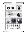
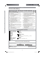
Explanation of the information signs on
the equipment (Fig. 14):
1. Warning!
2. Read the instructions before using for the fi rst
time!
3. Wear protective headgear, goggles and ear
muffs!
4. Wear sturdy, non-slip footwear!
5. Wear safety gloves!
6. Protect the equipment from rain and damp!
7. Be careful of objects being catapulted away!
8. Always switch off the equipment and pull out
the spark boot plug before carrying out any
maintenance work!
9. The distance between the equipment and per-
sons in the vicinity must be at least 15 m!
10. The cutting tool (blade/cutting line) continues
to rotate after the machine is switched off!
11. Caution: Hot equipment parts. Keep your dis-
tance!
12. Add a little grease (gear grease) after every
20 hours in operation!
13. Note: Left-handed thread. Turn clockwise
to undo the tool, turn counter-clockwise to
tighten it.
Safety information
• Read the operating instructions carefully. Fa-
miliarize yourself with the settings and with the
proper use of the equipment.
• Never allow other persons who are not fami-
liar with the operating instructions to use the
equipment. Contact your local governmental
agency for information regarding minimum
age requirements for the user.
• Never mow in the direct vicinity of persons -
especially children - or animals.
Warning!
Maintain a safety distance of 15m. If approa-
ched, switch off the equipment immediately.
Always keep in mind that the user of the
equipment is responsible for accidents invol-
ving other persons or their property.
• Important: Danger of poisoning. Emissions,
fuels and lubricants are toxic. Do not inhale
emissions.
Before using
• Always wear sturdy, non-slip footwear and
long trousers when mowing. Never mow ba-
refoot or in sandals.
• Check the ground on which the equipment
will be used and remove all objects that could
be caught up and catapulted away.
• Warning! Petrol is highly flammable! There-
fore:
- Only store petrol in containers designed to
hold petroleum-based liquids.
- Only refuel out in the open and do not
smoke during the refuelling process.
- Always refuel before starting the engine. Do
not open the fuel tank cap and do not refuel
Anleitung_3401995_LB7.indb 9Anleitung_3401995_LB7.indb 9 04.12.12 15:5804.12.12 15:58

GB/CY
- 10 -
while the engine is running or when the equip-
ment is hot.
- If petrol has overflowed, do not under any
circumstances attempt to start the engine.
Instead, remove the equipment from the af-
fected area. Avoid starting the engine until the
petrol fumes have completely evaporated.
- For safety reasons, the petrol tank and the
tank cap must be replaced if they are dama-
ged.
• Replace defective silencers.
• Before using the scythe, visually inspect it to
ensure that the blade, mounting bolts and the
entire cutting apparatus are in good working
order (i.e. not worn out or damaged). To
prevent any imbalance, replace worn out or
damaged blades and mounting bolts as a set
only (if applicable).
Handling
(operation, storage, monitoring)
• Wear close-fitting work clothing which is in
good condition and which offers protection,
such as long trousers, sturdy work shoes,
hard-wearing gloves, a helmet, a face mask
or goggles to protect your eyes, and good
quality cotton wool in your ears or some other
ear protectors to reduce the noise.
• Store the equipment in a safe place. Open the
petrol tank cap slowly to release any pressure
that may have formed in the petrol tank. To
prevent the risk of fire, move at least 3 meters
from the refueling area before you start the
equipment.
• Switch off the equipment before you put it
down.
• Always hold the equipment firmly in both
hands. Your fingers and thumbs should be
wrapped around the handles.
• Ensure that all screws and connecting ele-
ments are secure. Never use the equipment if
it has not been properly adjusted or has not
been fully or safely assembled.
• Make sure that the handles are clean and dry
and that there is no petrol mixture on them.
• Set the line spool to the required height. Avoid
touching small objects such as stones with the
line spool.
• When carrying out mowing work on a slope
always stand at a lower level than the cutting
tool. Never cut or trim on a smooth, slippery
hill or slope.
• Keep all parts of your body and items of
clothing away from the line spool when you
start the engine and when the engine is run-
ning. Before you start the engine ensure that
the line spool will not strike an obstacle.
• Always switch off the engine before working
on the cutting tool.
• Store the equipment and accessories in a safe
place protected from naked flames and heat/
spark sources such as gas geyser heaters,
tumble driers, oil stoves or portable radiators,
etc.
• Keep the guard hood, line spool and engine
clear of mowing debris at all times.
• Only adequately trained people and adults
may use, adjust and maintain the equipment.
• If you are not familiar with the equipment,
practice handling it with the engine off.
• Always check the site you want to mow be-
fore you begin your work. Solid objects such
as pieces of metal, bottles, stones, etc. can be
catapulted away and cause serious injuries
and permanent damage to the equipment. If
you touch a solid object with the equipment
by mistake, switch off the engine immediately
and check the equipment for signs of dama-
ge. Never use the equipment if it is damaged
or defective.
• Always operate the equipment in its high
speed range for trimming and cutting. Do not
let the engine run at low speed at the start of
mowing or during trimming work.
• Only use the equipment for the purpose for
which it is intended, such as trimming and
mowing weeds.
• Never hold the line spool above knee height
when the equipment is in operation.
• Do not use the equipment if other people or
animals are in the immediate vicinity. Keep a
minimum distance of 15 m between yourself
and other people or animals when mowing.
Keep a distance of 30 m if you are mowing
down to the ground.
Anleitung_3401995_LB7.indb 10Anleitung_3401995_LB7.indb 10 04.12.12 15:5804.12.12 15:58

GB/CY
- 11 -
Additional instructions
• Do not use any fuel other than that recom-
mended in the operating instructions. Always
follow the instructions in the section „Fuel
and oil“. Do not use petrol that has not been
mixed correctly with 2-stroke oil. Other-
wise there is a risk of causing permanent
damage to the engine and of voiding the
manufacturer‘s guarantee.
• Do not smoke while refueling or using the
equipment.
• Never use the equipment without the exhaust
pipe.
• Do not touch the exhaust pipe with your
hands or body. Hold the equipment so that
your fingers and thumbs are wrapped around
the handled
• Do not use the equipment in an uncomfortable
posture, off balance, with extended arms or
with only one hand. Always use both hands
on the equipment and wrap your fingers and
thumbs around the handles.
• Always keep the line spool on the ground
whilst the equipment is in operation.
• Use the equipment only for the purpose for
which it is intended, such as trimming and
mowing weeds.
• Do not use the equipment over a lengthy peri-
od of time - take regular breaks.
• Do not use the equipment when under the
influence of alcohol or drugs.
• Use the equipment only when the guard hood
is fitted and in good working order.
• Any modifications to the product may place
your personal safety at risk and cause the
manufacturer’s warranty to be voided.
• Never use the equipment near inflammable li-
quids or gases, neither in enclosed rooms nor
outdoors. This may cause explosions and/
or fire.
• Do not use any other cutting tools. For your
own safety you must use only the accessories
and attachments which are listed in the ope-
rating instructions or which are recommended
or specified by the manufacturer. The use of
cutting tools or accessories other than those
recommended in the operating instructions
or catalog may place your personal safety
at risk.
Safety precautions for handling the blade
• Take not of all warnings and instructions rela-
ting to operating and fitting the blade.
• The blade can recoil suddenly from objects
if it cannot cut or mow through them. This
can cause injuries to the arms or legs. Keep
bystanders and animals at least 15 m away
from where you are working. If the equip-
ment strikes a foreign body, stop the engine
immediately and wait for the blade to come
to a standstill. Check the blade for signs of
damage. Always replace the blade if it is bent
or cracked.
• The blade is liable to catapult away objects
with high force. This can cause blindness or
injuries. Wear protection on your eyes, face
and legs. Always remove objects from your
working area before you use the blade.
• Carefully check the equipment and its fittings
for signs of damage every time before use.
Do not use the equipment unless all the blade
fittings are installed correctly.
• When you release the throttle lever, the blade
will continue to rotate and will only gradually
come to a standstill. A blade which is in the
process of rotating to a standstill can cause
you or bystanders injuries through cutting. Be-
fore you start any work on the blade, switch
off the engine and ensure that the blade has
come to a standstill.
• The danger zone has a radius of 15 meters.
Bystanders may suffer blindness or injuries.
Keep a distance of 15 meters between your-
self and other people or animals.
Anleitung_3401995_LB7.indb 11Anleitung_3401995_LB7.indb 11 04.12.12 15:5804.12.12 15:58

GB/CY
- 12 -
3. Layout and items supplied
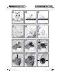
3.1 Layout (Fig. 1-13)
1. Connecting piece for long handle
2. Long handle
3. Steady grip
4. Starter line / starter cable
5. Choke lever
6. Petrol tank
7. Fuel pump „primer“
8. Air fi lter housing cover
9. On/Off switch
10. Throttle lever lock
11. Throttle lever
12. Throttle lock
13. Line spool with cutting line
14. Cutting line guard hood
15. Cutting blade guard hood
16. Screw M5 (4x)
17. Carrying strap
18a. Cutting blade (4 teeth)
18b. Cutting blade (3 teeth)
19. Holder for steady grip
20. Handle screw M8
21. Washer Ø 8mm
22. Carrier plate
23. Pressure plate
24. Pressure plate cover
25. Nut M10 (left-hand thread)
26. Oil/petrol mixing bottle
27. Spark plug wrench
28. Open-ended wrench 8/10 mm
29. Hex wrench 4 mm
30. Hex wrench 5 mm
31. Protective cap for spark boot plug
32. Handle screw M6
33. Nut M6
34. Washer Ø 6mm
35. Air fi lter
36. Spark boot plug
The cutting blade (18a/18b) and the line spool
(13) are jontly referred to in the text as the cutting
tool (generic term).
3.2 Items supplied
• Open the packaging and take out the equip-
ment with care.
• Remove the packaging material and any
packaging and/or transportation braces (if
available).
• Check to see if all items are supplied.
• Inspect the equipment and accessories for
transport damage.
• If possible, please keep the packaging until
the end of the guarantee period.
Important!
The equipment and packaging material
are not toys. Do not let children play with
plastic bags, foils or small parts. There is
a danger of swallowing or suffocating!
4. Intended use
The equipment (cutting blade mode) is designed
for cutting high grass and sparse scrub with the
4-tooth blade and for cutting dense scrub and
slender wood growth with the 3-tooth blade.
The equipment (line spool mode) is designed for
cutting lawns and small weeds. The operating
instructions as supplied by the manufacturer must
be obeyed to ensure that the equipment is used
properly.
Any use which is not expressly permitted in these
instructions may result in damage to the equip-
ment and place the user in serious danger. Be
sure to observe the restrictions in the safety infor-
mation.
Please note that our equipment has not been de-
signed for use in commercial, trade or industrial
applications. Our warranty will be voided if the
equipment is used in commercial, trade or indust-
rial businesses or for equivalent purposes.
Caution! Due to the high risk of physical injury to
the user, the equipment must not be used to carry
out the following work: to clean dirt and debris off
walkways, or to chop up tree or hedge clippings.
Similarly, the equipment must not be used to level
out high areas such as molehills. For safety rea-
Anleitung_3401995_LB7.indb 12Anleitung_3401995_LB7.indb 12 04.12.12 15:5804.12.12 15:58

GB/CY
- 13 -
sons, the equipment is not allowed to be used as
a drive unit for other tools of any kind.
The equipment is allowed to be used only for its
intended purpose. Any other use is deemed to be
a case of misuse. The user/operator and not the
manufacturer will be liable for any damage or
injuries of any kind resulting from such misuse.
5. Technical data
Engine type ...............................................................
........2-stroke engine, air-cooled, chrome cylinder
Engine power (max.) ..................1.35 kW/ 1.8 hp
Displacement ............................................42.7 ccm
Idle engine speed .................................3000 min-1
Max. engine speed
with blade: .............................................9000 min-1
with line spool: ......................................8400 min-1
Max. cutting speed
with blade: .............................................6800 min-1
with line spool: ......................................6300 min-1
Ignition ..................................................... Electronic
Drive ............................................Centrifugal clutch
Weight (with empty tank) .............................7.5 kg
Cutting circle diameter of line ...................... 41 cm
Cutting circle diameter of blade ..................23 cm
Cutting line length ..........................................8.0 m
Cutting line diameter ..................................2.0 mm
Tank capacity ...................................................0.8 l
Spark plug ..................................Champion RCJ6Y
Fuel consumption at
max. engine power ..................................0.6 kg/h
Specifi c fuel consumption
at max. engine power ........................446 g/kWh
Sound and vibration
LpA sound pressure level ...........................98 dB(A)
KpA uncertainty ............................................. 1.5 dB
LWA sound power level ...........................110 dB(A)
KWA uncertainty ............................................ 1.5 dB
Wear ear-muffs.
The impact of noise can cause damage to hea-
ring.
Operation
Vibration emission value ah = 4.1 m/s2
K uncertainty = 1.5 m/s2
Keep the noise emissions and vibrations
to a minimum.
• Only use appliances which are in perfect
working order.
• Service and clean the appliance regularly.
• Adapt your working style to suit the appli-
ance.
• Do not overload the appliance.
• Have the appliance serviced whenever ne-
cessary.
• Switch the appliance off when it is not in use.
• Wear protective gloves.
6. Before starting the
equipment
6.1 Assembly
6.1.1 Fitting the steady grip (Fig. 3a-3c)
Fit the steady grip (3) as shown in Figures 3a-3c.
Do not tighten the screw (20) until you have set
the optimum working position with the carrying
strap (17) (see also section 6.2). The steady grip
should be aligned as shown in Figure 1. To dis-
mantle, proceed in reverse order.
6.1.2 Fitting the long handle (Fig. 4a-4c)
Pass the handle screw (32) through the washer
(34) and into the connecting piece of the long
handle (1). Secure the handle screw loosely
with the nut (33). Now press the locking lever
(A) and push the long handle (Fig. 4a/Item 2)
carefully into the connecting piece for the long
handle. While doing so, ensure that the drive
shafts on the inside of the long handle slide into
each other (turn the line spool (13) / cutting bla-
de (18a/18b) gently if required). The lug of the
locking lever (A) must latch into the hole (B). Now
tighten the handle screw as shown in Figure 4c. To
Anleitung_3401995_LB7.indb 13Anleitung_3401995_LB7.indb 13 04.12.12 15:5804.12.12 15:58

GB/CY
- 14 -
dismantle, simply slacken the handle screw and
actuate the locking lever.
6.1.3 Fitting the blade guard hood
Important: The cutting blade guard hood (15)
must be fi tted when you want to work with the
cutting blade.
The guard hood for the cutting blade must be ins-
talled as shown in Figures 5a – 5b.
6.1.4 Fitting/Replacing the cutting blade
The procedure for fi tting the cutting blade
(18a/18b) is shown in Figures 6a-6g. To dismant-
le, proceed in reverse order.
• Fit the carrier plate (22) onto the spline shaft
as shown in Figure 6b.
• Secure the cutting blade (18a/18b)) on the
carrier plate (Fig. 6c).
• Place the pressure plate (23) over the thread
of the spline shaft (Fig. 6d).
• Plug on the cover of the pressure plate (24)
(Fig. 6e).
• Look for the hole in the carrier plate, line up
with the notch underneath, lock with the sup-
plied hex wrench (29), and then tighten the
nut (25) with the spark plug wrench (27) (Fig.
6f/6g). Important: Left-hand thread
• The cutting blades (18a/18b) are delivered
with plastic protective caps fitted to them.
Remove these caps before use and refit them
after use.
6.1.5 Fitting the cutting line guard hood
on the cutting blade guard hood
Important: The cutting line guard hood (14) must
be fi tted in addition when you want to work with
the cutting line.
The guard hood for the cutting line must be ins-
talled as shown in Figures 7a – 7b. Make sure
that the cutting line guard hood engages correctly.
A blade (Fig. 7a/ Item F) on the underside of the
guard hood automatically cuts the cutting line to
the optimum length. It is covered by a guard (Fig.
7a/Item G).
Remove the guard before you start working and
replace it when you have fi nished working.
6.1.6 Fitting/Replacing the line spool
The procedure for fi tting the line spool (13) is
shown in Figure 7c. To dismantle, proceed in re-
verse order. The line spool is already fi tted when
the equipment is delivered.
Look for the hole in the carrier plate (22), line up
with the notch beneath it, lock with the supplied
hex wrench (29), and screw the line spool onto
the thread.
Important: Left-hand thread
6.2 Setting the cutting height
• Fit the carrying strap (17) as shown in Figures
8a-8c.
• Hook the equipment to the carrying belt (Fig.
8d).
• Adjust to the perfect working and cutting po-
sition using the various strap adjusters on the
carrying strap (Fig. 8e).
• To confirm the optimum length of the carrying
strap, make a few swinging movements with
the engine off (Fig. 9a).
The carrying strap is fi tted with a quick-release
mechanism. Pull the red strap section (Fig. 8f) if
you need to remove the strap quickly.
Important: Always use the strap when working
with the equipment. Attach the strap as soon as
you have started the engine and it is running in
idle mode. Switch off the engine before you take
off the carrying strap.
6.3 Fuel and oil
Recommended fuels
Use only a mixture of unleaded petrol and special
2-stroke engine oil.
Mix the fuel mixture as indicated in the fuel mixing
table.
Important: Do not use a fuel mixture which has
been stored for longer than 90 days.
Important: Never use 2-stroke oil with a recom-
mended mixing ratio of 100:1. The manufacturer’s
warranty will be voided in case of engine dama-
ge due to inadequate lubrication.
Important: Only use containers designed and
approved for the purpose to transport and store
Anleitung_3401995_LB7.indb 14Anleitung_3401995_LB7.indb 14 04.12.12 15:5804.12.12 15:58

GB/CY
- 15 -
fuel. Pour the correct quantities of petrol and
2-stroke oil into the mixing bottle (see scale prin-
ted on the bottle). Then shake the bottle well.
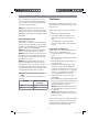
6.4 Fuel mixing table
Mixing procedure: 40 parts petrol to 1 part oil
Petrol 2-stroke oil
1 liter 25 ml
5 liters 125 ml
7. Operation
Please note that the statutory regulations gover-
ning noise abatement may differ from one loca-
tion to another.
Each time before use, check the following :
• That there are no leaks in the fuel system.
• That the equipment is in perfect condition and
that the safety devices and cutting devices are
complete.
• That all screws are securely fastened.
• That all moving parts move smoothly.
7.1 Starting the engine when cold
Fill the tank with the oil/petrol mix. See also „Fuel
and oil“.
1. Set the equipment down on a hard, level sur-
face.
2. Press the fuel pump (primer) (Fig. 1/Item 7)
10 times.
3. Move the On/Off switch (Fig. 1/Item 9) to
„I“.
4. Secure the throttle lever (Fig. 1 / Item 11).
To do this, press the throttle lever lock (Fig.
1/Item 12) and then press the throttle lever
(Fig. 1/Item 11) and lock the throttle lever by
pressing the lock (Fig. 1/Item 10) at the same
time.
5. Set the choke lever (Fig. 1/Item 5) to “ ”.
6. Hold the equipment fi rmly and pull out the
starter cable (Fig. 1/Item 4) until you feel it
begin to resist. Then tug sharply on the starter
cable 4 times. The equipment should start.
Important: Never allow the starter line to
snap back. This may result in damage.
Important: Since the throttle lever is secu-
red, the cutting tool starts to operate when the
engine is started.
Then release the throttle lever by actuating it once.
Actuating the throttle lever will also release the
choke lever. (The engine returns to its idle state).
7. If the engine does not start up, repeat steps
4-6 above.
Please note: If the engine does not start up
even after several attempts, read the section
„Troubleshooting“.
Please note: Always pull out the starter cable
in a straight line. If it is pulled out at an angle,
friction will occur on the eyelet.
As a result of this friction, the starter line will
become frayed and will wear away faster.
Always hold the starter cable when the starter
line retracts.
Never allow the starter line to snap back
when it has been pulled out.
7.2 Starting the engine when warm
(The equipment has been idle for less than 15-20
min.)
1. Set the equipment down on a hard, level sur-
face.
2. Switch the On/Off switch to “I” (Fig. 1 / Item
9).
3. Secure the throttle lever (Fig. 1 / Item 11) (in
the same way as described in “Starting the
engine when cold”).
4. Hold the equipment fi rmly and pull out the
starter cable until you feel it start to resist. Then
tug sharply on the starter cable. The equip-
ment should start after 1-2 tugs. If the equip-
ment does not start after 6 tugs, repeat steps
1 – 7 of the procedure for starting the engine
from cold.
Anleitung_3401995_LB7.indb 15Anleitung_3401995_LB7.indb 15 04.12.12 15:5804.12.12 15:58

GB/CY
- 16 -
7.3 Switching off the engine
Emergency Stop procedure:
If it becomes necessary to stop the equipment
immediately, set the On/Off switch (9) to “Stop”
or “0”.
Normal procedure:
Let go of the throttle lever (11) and wait until the
engine has changed to idling speed. Then set the
On/Off switch (9) to “Stop” or “0”.
7.4 Practical tips
Practice all the work steps with the engine swit-
ched off before you start to use the equipment.
Warning! Take extreme care during mowing
work. When doing such work keep a distance of
30 meters between yourself and other people or
animals.
Extending the cutting line
Warning! Do not use any kind of metal wire or
metal wire encased in plastic in the line spool. This
may cause serious injuries to the user.
To extend the cutting line (13), run the engine at
full speed and tap the line spool on the ground.
This will automatically extend the line. The blade
on the guard hood will cut the line to the permissi-
ble length (Fig. 9b).
Important: Remove all grass and weed rem-
nants at regular intervals to prevent the equipment
from overheating.
Grass and weed remnants become trapped under
the guard hood (Fig. 9c) and prevent the equip-
ment from cooling suffi ciently. Remove the rem-
nants carefully using a screwdriver or the like.
Different cutting methods
When the equipment is correctly assembled it will
cut weeds and long grass in places which are dif-
fi cult to access, e.g. along fences, walls and foun-
dations and also around trees. It can also be used
for „mowing“ down vegetation so that a garden
can be better prepared or a certain area cleared
down to the soil.
Please note: Even if it is used carefully, cutting
around foundations, stone or concrete walls, etc.
will result in the line suffering more than the nor-
mal level of wear.
Trimming/mowing (with line spool/cut-
ting blade)
Swing the equipment from side to side in a
scything motion. Always keep the cutting tool par-
allel to the ground.
Check the site and decide which cutting height
you require. Guide and hold the cutting tool at
the required height to ensure that you cut evenly
(Fig. 9d).
Low trimming (with line spool)
Hold the equipment right in front of you at a slight
angle so that the underside of the line spool is
above the ground and the line strikes the correct
target. Always cut away from yourself. Never
draw the equipment towards yourself.
Cutting along fences/foundations (with
line spool)
Approach wire mesh fences, lath fences, natural
stone walls and foundations slowly so that you
can cut close to them without striking the obstac-
le with the line. If, for example, the line strikes
stones, stone walls or foundations, it will wear or
fray. If the line strikes wire fencing, it will break.
Trimming around trees (with line spool)
When trimming around tree trunks, approach
slowly so that the line does not strike the bark.
Walk around the tree and take care not to dama-
ge the tree. Approach grass or weeds with the tip
of the line and tilt the line spool forwards slightly.
Mowing down to the ground (with line
spool)
When mowing down to the ground you will cut all
the vegetation. To do this, set the line spool at an
angle of 30° to the right. Place the handle in the
required position (Fig. 9e).
Caution! Increased risk of injury to the user,
bystanders and animals, and increased risk of
damaging property due to objects (e.g. stones)
being catapulted away.
Anleitung_3401995_LB7.indb 16Anleitung_3401995_LB7.indb 16 04.12.12 15:5804.12.12 15:58

GB/CY
- 17 -
Caution! Do not use the equipment to remove
objects from footpaths, etc.
The petrol scythe is a powerful tool and can cata-
pult small stones and other objects a distance of
15 meters or more, causing injuries and damage
to cars, houses and windows.
Sawing
The equipment is not suitable for sawing.
Jamming
If the cutting tool jams as a result of attempting
to cut vegetation that is too dense, switch off the
engine immediately. Remove the grass and scrub
from the equipment before you restart it.
Preventing recoil
When you work with the blade, there is a risk of
recoil if it strikes solid objects (tree trunks, bran-
ches, tree stumps, stones or the like). This will
throw the equipment backwards in the direction
opposite to the rotation of the cutting tool. This can
cause you to lose control of the equipment. Do not
use the blade near fences, metal posts, boundary
stones or foundations. For cutting slender wood
growth, position the equipment as shown in Fig. 9f
in order to prevent recoil.
8. Maintenance and ordering
of spare parts
Always switch off the equipment and pull out the
spark boot plug (36) before carrying out any
maintenance work.
8.1 Replacing the line spool/cutting line
1. Dismantle the line spool (13) as described in
section 6.1.6. Press the spool together (Fig.
12a) and remove one half of the housing (Fig.
12b).
2. Take the spool plate (K) out of the line spool
housing (Fig. 12c).
3. Remove any remaining cutting line.
4. Place the new cutting line in the center and
hang the loop which has formed into the re-
cess in the spool splitter. (Fig. 12d)
5. Wind up the line counter-clockwise and under
tension. The spool splitter will separate the
two halves of the line. (Fig. 12e)
6. Hook the last 15 cm of the two ends of the
line onto the opposite lying line holders of the
spool plate. (Fig. 12f)
7. Thread the two ends of the line through the
metal eyelets in the line spool housing (Fig.
12c).
8. Press the spool plate into the line spool
housing (Fig. 12b).
9. Pull the two line ends sharply to release them
from the line holders.
10. Join the housing parts together again.
11. Cut the excess line to a length of around 13
cm. This will reduce the load on the engine
when starting and warming up.
12. Refi t the line spool (see section 6.1.6). If you
are replacing the complete line spool, skip
points 3-6.
8.2 Maintenance of the air fi lter
Soiled air fi lters reduce the engine output by sup-
plying too little air to the carburetor.
Regular checks are therefore essential.
The air fi lter (35) should be checked after every
25 hours of use and cleaned if necessary. If the
air contains a lot of dust, the air fi lter should be
checked more frequently.
1. Remove the cover from the air fi lter housing
(Fig. 10a / Item 8)
2. Remove the air fi lter (Fig. 10b/10c)
3. Clean the air fi lter by tapping it or blowing it
out (with compressed air).
4. Assemble in reverse order.
Important: Never clean the air fi lter with petrol
or infl ammable solvents.
Anleitung_3401995_LB7.indb 17Anleitung_3401995_LB7.indb 17 04.12.12 15:5804.12.12 15:58

GB/CY
- 18 -
8.3 Maintenance of the spark plug
Electrode gap = 0.6 mm (distance between the
electrodes between which the ignition spark is
created). Tighten the spark plug with 12 to 15 Nm
using a torque wrench (available from your dea-
ler). Check the spark plug for dirt and grime after
10 hours of operation and if necessary clean it
with a copper wire brush.
Thereafter service the spark plug after every 50
hours of operation.
1. Dismantle the protective cap (Fig. 10c/Item
31) using a screwdriver.
2. Pull off the spark boot plug (Fig. 11a/Item
36).
3. Remove the spark plug (Fig. 11b) with the sup-
plied spark plug wrench (27).
4. Assemble in reverse order.
8.4 Sharpening the guard hood blade
The guard hood blade (Fig. 7a/Item F) can be-
come blunt over time. If you notice this, undo the
two screws holding the guard hood blade to the
guard hood. Clamp the blade in a vise. Sharpen
the blade with a fl at fi le and make sure that the
angle of the cutting edge is not altered in the pro-
cess. File in one direction only.
8.5 Carburetor settings
Important: Settings on the carburetor are allo-
wed to be made by authorized customer service
personnel.
The air fi lter housing cover must be removed
before any work on the carburetor, as shown in
Figures 10a and 10b.
Setting the throttle cable:
If the maximum speed of the equipment drops
over time and you have ruled out all the other
possible causes listed in the section „Troubleshoo-
ting“, it may be necessary to adjust the throttle
cable.
First of all check whether the carburetor opens ful-
ly when the throttle lever is pressed right through.
This is the case if the carburetor slide (Fig. 13a/
Item F) is completely opened when the throttle is
fully activated.
Figure 13a shows the correct setting. If the car-
buretor slide is not completely open, it must be
adjusted.
The following steps are required to adjust the
throttle cable:
• Undo the lock nut (Fig. 13b/Item C) a few
turns.
• Undo the adjusting screw (Fig. 13b/Item D)
until the carburetor slide is completely open
when the throttle is fully activated, as shown in
Figure 13a.
• Retighten the lock nut.
Setting the idling speed:
Caution! Set the idling speed when the equip-
ment is warm.
If the engine stalls when the throttle is not pressed
and you have ruled out all the other possible
causes listed in the section „Troubleshooting“, the
idling speed must be adjusted. To do this turn the
idling speed screw (Fig. 13b/Item E) clockwise
until the equipment runs smoothly at idling speed.
If the idling speed is so fast that the cutting tool
turns as well, it has to be reduced by turning the
idling speed screw for as long as is required for
the cutting tool to stop turning as well.
8.6 Applying grease to the gear unit
Add a little gear grease (approx. 10 g) after
every 20 hours in operation. To do so, open the
screw H (Fig. 7c).
8.7 Environmental protection
Dispose of soiled maintenance material and
operating materials at the appropriate collection
point.
Recycle packaging material, metal and plastics.
8.8 Ordering replacement parts
Please provide the following information on all
orders for spare parts:
• Type of unit
• Article number of the unit
• ID number of the unit
For current prices and information please visit
www.isc-gmbh.info
Anleitung_3401995_LB7.indb 18Anleitung_3401995_LB7.indb 18 04.12.12 15:5804.12.12 15:58

GB/CY
- 19 -
9. Storage and transport
9.1 Storage
Important: Never put the equipment into sto-
rage for longer than 30 days without carrying out
the following steps.
Storing the equipment
If you intend to store the equipment for longer
than 30 days, it must be prepared accordingly.
Otherwise the fuel still remaining in the carburetor
will evaporate and leave a rubbery sediment.
This can cause problems when starting up the
equipment and may require expensive repairs.
1. Slowly remove the fuel tank cap to release
any pressure that may have formed in the
tank. Carefully empty the tank (6).
2. To remove the fuel from the carburetor, start
the engine and let it run until the equipment
stops.
3. Leave the engine to cool (approx. 5 minutes).
4. Remove the spark plug (see 8.3).
5. Add one teaspoon of 2-stroke engine oil into
the combustion chamber. Slowly pull the star-
ter cord several times to apply a layer of oil
to all internal components. Fit the spark plug
again.
Note: Store the equipment in a dry place and
far away from possible ignition sources such as
an oven, a gas-fi red hot water boiler, a gas-fi red
dryer, etc.
Putting the equipment back into opera-
tion
1. Remove the spark plug (see 8.3).
2. Quickly tug on the starter line to remove ex-
cess oil from the combustion chamber.
3. Clean the spark plug and check that the elec-
trode gap is correct, or insert a new spark
plug with the correct electrode gap.
4. Prepare the equipment for operation.
5. Fill the tank with the relevant mixture of fuel
and oil. See the section “Fuel and oil”.
9.2 Transport
To transport the equipment, empty the petrol tank
as described in the section “Storage”. Clean
coarse dirt off the equipment with a brush or hand
brush. Dismantle the steady grip and the long
hande as described in section 6.1.1 and 6.1.2.
10. Cleaning
Always switch off the equipment and pull out the
spark boot plug before carrying out any cleaning
work.
• The equipment should be cleaned thoroughly
every time after it has been used. This applies
particularly to the cutting tool and the guard
hoods.
• Keep the air vents and the motor housing free
of dirt and dust as far as possible. Wipe the
equipment with a clean cloth or blow it down
with compressed air at low pressure.
• It is easiest to remove dirt and grass immedia-
tely after mowing.
• Clean the equipment regularly with a damp
cloth and some soft soap. Do not use cleaning
agents or solvents; these may be aggressive
to the plastic parts in the equipment. Ensure
that no water can get into the interior of the
equipment.
11. Disposal and recycling
The equipment is supplied in packaging to prevent
it from being damaged in transit. The raw materi-
als in this packaging can be reused or recycled.
The equipment and its accessories are made of
various types of material, such as metal and plas-
tic. Defective components must be disposed of as
special waste. Fuel and oil must be disposed of
only at special refuse collection centers. Ask your
dealer or your local council.
Anleitung_3401995_LB7.indb 19Anleitung_3401995_LB7.indb 19 04.12.12 15:5804.12.12 15:58

GB/CY
- 20 -
12. Troubleshooting
Fault Possible cause Troubleshooting
The equipment does
not start
- Correct starting procedure not follo-
wed
- Sooted or damp spark plug
- Incorrect carburetor setting
- Follow the instructions for starting
- Clean the spark plug or replace it
with a new one
- Contact an authorized customer
service outlet or send the equipment
to ISC-GmbH
The equipment starts
but does not deve-
lop its full power
- Incorrect choke lever (5) setting
- Soiled air fi lter (35)
- Incorrect carburetor setting
- Set the choke lever to “ ”
- Clean the air fi lter
- Contact an authorized customer
service outlet or send the equipment
to ISC-GmbH
The engine does not
run smoothly
- Incorrect electrode gap on the
spark plug
- Incorrect carburetor setting
- Clean the spark plug and adjust the
electrode gap or fi t a new spark
plug
- Contact an authorized customer
service outlet or send the equipment
to ISC-GmbH
Engine smokes ex-
cessively
- Incorrect fuel mix
- Incorrect carburetor setting
- Use the correct fuel mix (see fuel
mixing table)
- Contact an authorized customer
service outlet or send the equipment
to ISC-GmbH
Anleitung_3401995_LB7.indb 20Anleitung_3401995_LB7.indb 20 04.12.12 15:5804.12.12 15:58
Pagina se încarcă...
Pagina se încarcă...
Pagina se încarcă...
Pagina se încarcă...
Pagina se încarcă...
Pagina se încarcă...
Pagina se încarcă...
Pagina se încarcă...
Pagina se încarcă...
Pagina se încarcă...
Pagina se încarcă...
Pagina se încarcă...
Pagina se încarcă...
Pagina se încarcă...
Pagina se încarcă...
Pagina se încarcă...
Pagina se încarcă...
Pagina se încarcă...
Pagina se încarcă...
Pagina se încarcă...
Pagina se încarcă...
Pagina se încarcă...
Pagina se încarcă...
Pagina se încarcă...
Pagina se încarcă...
Pagina se încarcă...
Pagina se încarcă...
Pagina se încarcă...
Pagina se încarcă...
Pagina se încarcă...
Pagina se încarcă...
Pagina se încarcă...
Pagina se încarcă...
Pagina se încarcă...
Pagina se încarcă...
Pagina se încarcă...
Pagina se încarcă...
Pagina se încarcă...
Pagina se încarcă...
Pagina se încarcă...
Pagina se încarcă...
Pagina se încarcă...
Pagina se încarcă...
Pagina se încarcă...
Pagina se încarcă...
Pagina se încarcă...
Pagina se încarcă...
Pagina se încarcă...
Pagina se încarcă...
Pagina se încarcă...
Pagina se încarcă...
Pagina se încarcă...
Pagina se încarcă...
Pagina se încarcă...
Pagina se încarcă...
Pagina se încarcă...
Pagina se încarcă...
Pagina se încarcă...
Pagina se încarcă...
Pagina se încarcă...
Pagina se încarcă...
Pagina se încarcă...
Pagina se încarcă...
Pagina se încarcă...
Pagina se încarcă...
Pagina se încarcă...
Pagina se încarcă...
Pagina se încarcă...
Pagina se încarcă...
Pagina se încarcă...
-
 1
1
-
 2
2
-
 3
3
-
 4
4
-
 5
5
-
 6
6
-
 7
7
-
 8
8
-
 9
9
-
 10
10
-
 11
11
-
 12
12
-
 13
13
-
 14
14
-
 15
15
-
 16
16
-
 17
17
-
 18
18
-
 19
19
-
 20
20
-
 21
21
-
 22
22
-
 23
23
-
 24
24
-
 25
25
-
 26
26
-
 27
27
-
 28
28
-
 29
29
-
 30
30
-
 31
31
-
 32
32
-
 33
33
-
 34
34
-
 35
35
-
 36
36
-
 37
37
-
 38
38
-
 39
39
-
 40
40
-
 41
41
-
 42
42
-
 43
43
-
 44
44
-
 45
45
-
 46
46
-
 47
47
-
 48
48
-
 49
49
-
 50
50
-
 51
51
-
 52
52
-
 53
53
-
 54
54
-
 55
55
-
 56
56
-
 57
57
-
 58
58
-
 59
59
-
 60
60
-
 61
61
-
 62
62
-
 63
63
-
 64
64
-
 65
65
-
 66
66
-
 67
67
-
 68
68
-
 69
69
-
 70
70
-
 71
71
-
 72
72
-
 73
73
-
 74
74
-
 75
75
-
 76
76
-
 77
77
-
 78
78
-
 79
79
-
 80
80
-
 81
81
-
 82
82
-
 83
83
-
 84
84
-
 85
85
-
 86
86
-
 87
87
-
 88
88
-
 89
89
-
 90
90


FLORABEST FBS 43 A1 Instrucțiuni de utilizare
- Tip
- Instrucțiuni de utilizare
în alte limbi
Alte documente
-
EINHELL GC-MM 52 I AS Original Operating Instructions
-
-
-
-
 Bavaria Black 34.046.55 Instrucțiuni de utilizare
-
Stiga SBC645KD Instrucțiuni de utilizare
-
 Nakayama PB5221 Manual de utilizare
-
Hitachi CG 40EASP Handling Instructions Manual
-
Stiga B 26 D Instrucțiuni de utilizare

